Remember the movie “Groundhog Day “? Original Saturday Night Live cast member Bill Murray re-lives Groundhog Day over and over again. And still again. Kinda like the ESP8266 when it repeatedly resetting… Nothing you try makes a difference!
If you have worked with the ESP8266 for any length of time, you have undoubtedly experienced the endless resets on power-up. The looping message occurs at about 5 second intervals, which seems to be the default internal watchdog timer time-out period. The message, at 115200 baud, looks something like this:
ets Jan 8 2013,rst cause:4, boot mode:(3,7)
wdt reset
load 0x40100000, len 30000, room 16
tail 0
chksum 0x67
load 0x3ffe8000, len 2556, room 8
tail 4
chksum 0xb7
load 0x3ffe8a00, len 3080, room 4
tail 4
chksum 0x59
csum 0x59
r”
I have yet to come across a definitive explanation for this behavior.
Is this the boot-loader?
The core firmware?
Perhaps a chip defect?
From what I have experienced and read from other users, there are two likely hardware causes that makes logical sense:
- Inadequate power supply interface
- A flash chip failure.
In order to prevent resets, you must include the following three features in the power source to the ESP8266.
- Sufficient current. A regulated 3.3V source of at least 500ma is essential. Aside from the 300ma peak current needs of the ESP8266, it is essential to also consider the current requirements for other components you have – like the sensors and controls in your circuit.
- A large capacitor (suggest using 470 uF) across the Vcc to Gnd rails on your breadboard or PCB is a vital ingredient that will minimize reset inducing voltage fluctuations.
- A 0.1 uF decoupling capacitor across the ESP8266 Vcc to Gnd inputs very close to the pins (within 1/2 inch). DO NOT SKIP THIS COMPONENT! This cheap yet often overlooked component, when missing, is the root cause of ESP8266 resets.
Even with these power supply precautions, we know the flash chip (25Q40) used with many of these ESP8266 module is of low quality and fails after only a few flash cycles. Perhaps sending the code somewhere that it never returns from. Triggering the watchdog timer to reset the unit.
I currently have some replacement flash chips on order and shall see if replacing that chip does indeed remedy the unwanted power-up resets. Unfortunately, my ESP8266-12 (-7 also) has a metal shield over the active components, including the flash chip. This will have to be removed in order to gain access to the memory chip. Removing the shield will require a heat gun—and may very well damage the ESP8266 component. That will be done as last resort, when the reset loops appear to be a permanent condition, rendering the module a “brick”.
But for me, I have not had either of my 2 prototyping ESP8266 assemblies fall into a non-repairable reset loop state yet. If the power supply measures noted above are in place, but you are still experiencing resets, here are a few steps I have been taking with some success to bring back to life an ESP8266 stuck in a ‘Groundhog Day’ reset loop:
Note: Since the entire ESP8266 module is so cheap, if you do not wish to invest your precious time in reviving your module, simply chuck it and start again with another unit. Otherwise, read on, here are 4 methods to correct an ESP8266 stuck repeating reset loops endlessly…
1. Check your connections
This seems obvious. But I have not seen this to be a problem with other MPUs, like an Arduino, Spark Core and even PIC processors.
But my first two ESP8266 set-ups use a standard solder-less breadboard. I have heard that the ESP8266 is very sensitive to intermittent connections, and the solder-less breadboard is not recommended. And sure enough, it has been a problem in my setup. While I have since switched to use soldered contacts on a prototyping vector-board, I am still using the two original breadboards for initial testing. Using these units to limit the flash cycles on the more permanent soldered set-ups.
I have already flashed these 2 initial units a couple hundred times, and counting…
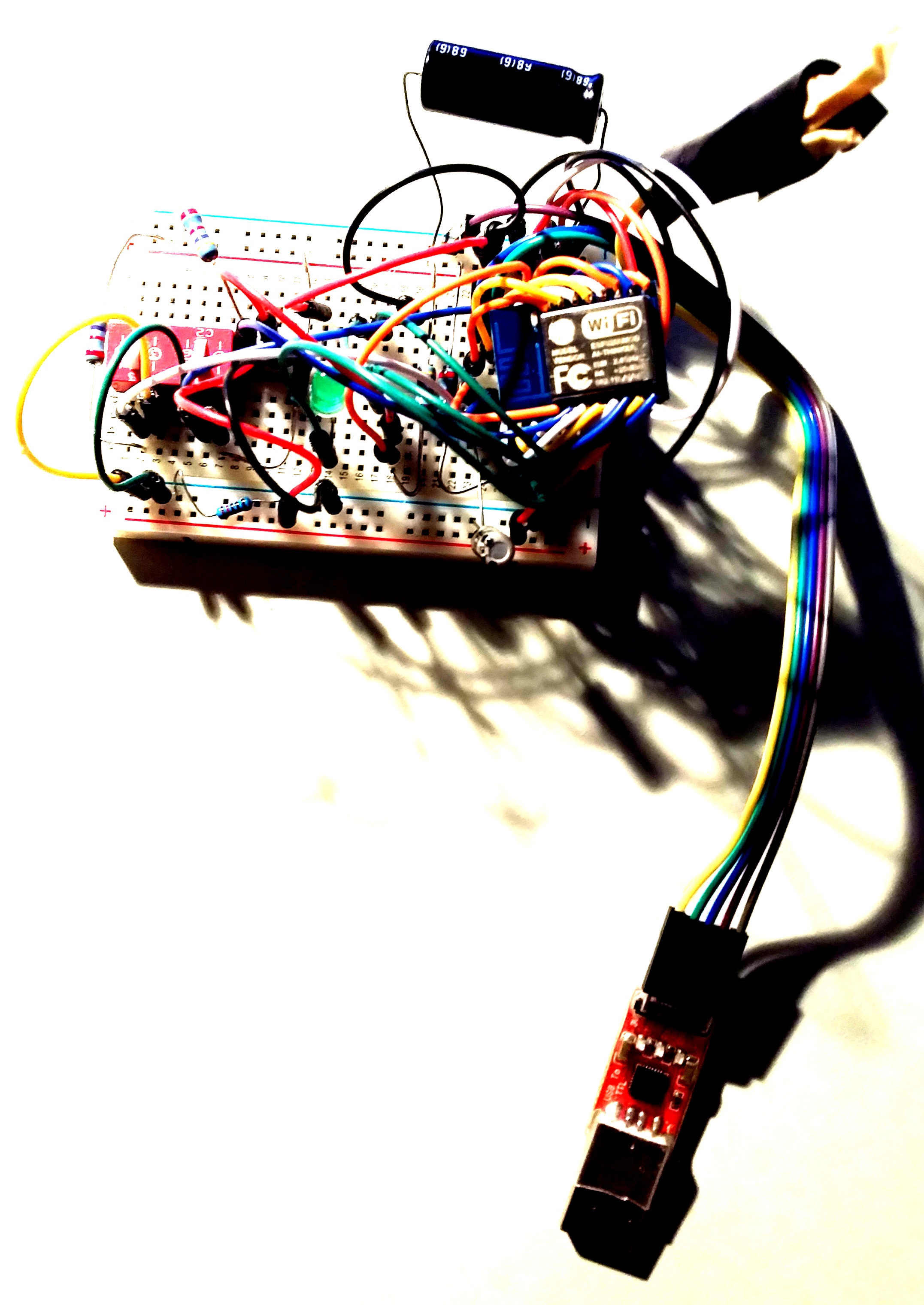
Solder-less breadboard set-up
After many frustrating and unsuccessful attempts to revive my original setup out of reset purgatory, I made a final inspection of the jumpers and found a few of them only partially engaged.
After securing all the connections again…
The phoenix rose from the ashes. Yes, I had just about given up on this unit And now, the next flash successfully restored the set-up out it’s reset loops. The module was spared the life threatening heat gun!
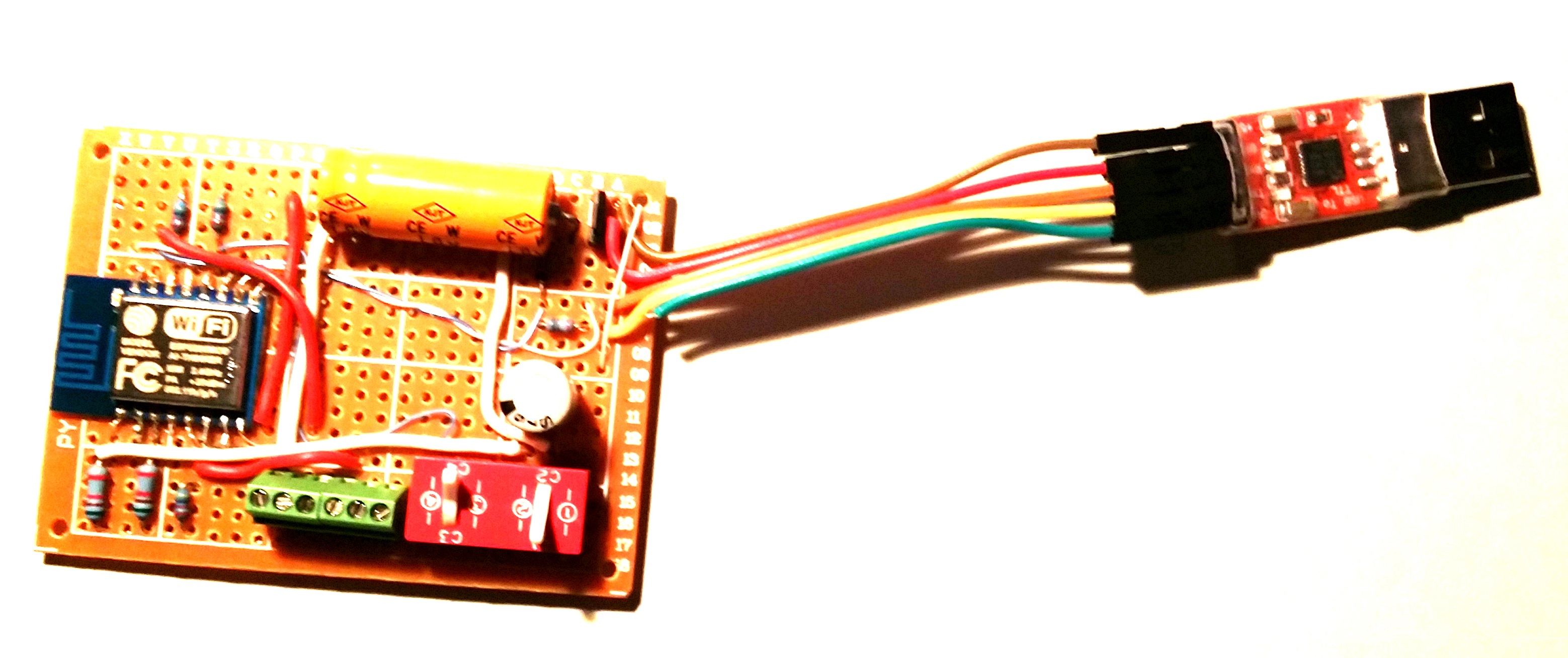
Soldered Printed Circuit Board set-up
2. Clear the memory
Along with securing connections, flashing some of the original binaries back into the module has always worked for me to clear the reset problem, so far. As I have already mentioned, it appears that the code gets stuck somewhere that it never returns from, resulting in a wdt reset. This would seem to be as result of corrupted memory. So clearing the flash memory, if possible, should correct the endless reset condition.
Here is what I have found to work:
2.1 Flash AT command set
Flash the ESP8266 with original AT command binary. In case you do not have the flasher, one place to get it: https://drive.google.com/file/d/0B3dUKfqzZnlwVGc1YnFyUjgxelE/view
Restarting the module in normal mode (GPIO2 HI) should result in a 115200 baud start-up message ending with “ready”. And it should respond to the “AT” command with “OK”.
If so, sweet! –-you are good to go.
But it is not always resolved that easily. Sometimes you got to dig deeper. If, your start-up message ends with “jump to user1” and then stops, additional steps will be needed to restore the module.
2.2 Flash blank.bin
Flashing the blank.bin file, which comes with the nodemcu flasher program, is another method to clear the memory. Using the nodemcu flasher, flash the 4K blank.bin to the following 5 starting addresses:
0x00000, 0x01000, 0x40000, 0x7c000, 0x7e000
Then repeat “2.1 Flash AT command set” above.
2.3 Flash blank to the entire 512 kbytes
I have also created a 512 kbyte version of the blank.bin file to clear the entire flash chip. After flashing this file to 0x00000, the entire flash memory address space is cleared.
After clearing the entire flash chip, I have found it necessary to flash the 4 files in the following zip.
https://developer.mbed.org/media/uploads/sschocke/esp_flasher.zip
Once this is complete, again, repeat “2.1 Flash AT command set” above.
3. Replace the flash memory chip
When all else fails, replace the flash memory chip. This involves soldering to remove the faulty 8-pin device and replacing it with a new one. While I do not have a known source to recommend, there are many to choose from on Aliexpress.com. Like the ESP8266, the flash chips are inexpensive, but there is no way to know for sure about the quality. At a minimum, read the reviews from other buyers before placing your order.
4. Software design considerations
There have been problems experienced that could not be overcome using the nodeMCU/lua and SDK development environments. I will write a blog post soon to document those issues. So the following considerations use the Arduino IDE, which is the only development IDE that has been both effective and reliable in implementing my program requirements at this time…
I have yet to find any information that provides the developer much control over the watchdog timer (wdt). The API simply allows you to enable/disable the timer and to “feed” it. I assume “feed” resets the timer although I have not found any documentation to support that assumption. I have found the following steps necessary to eliminate my IoT software application induced resets:
-
The wdt is enabled by default. It should be enabled during normal application operation. If it is disabled in software, instead of resetting, the ESP8266 will halt when a wdt timeout occurs.
-
It is important to return control to the processors periodically. This is done using the yield() or delay() statements. For example, sensor readings requiring more that 0.5 seconds to complete should be followed by a yield() or delay().
-
In addition to yielding control, I have found it necessary to “feed” the wdt periodically to prevent time-consuming tasks from tripping a wdt reset.
Hopefully this helps someone who has struggled with unwanted module resets.
Social tagging: ESP8266 flakey > ESP8266 resets > ESP8266 unstable > internet of things home
hey tnx for the info, i have a Node MCU V1.0 and ai trying to use a Stepper motor, for a project but i receive the message: ets Jan 8 2013,rst cause:4, boot mode:(3,7). I’m trying to use a ULN2003 controller for my stepper motor and ULN haves an independent power supply
what can i do?
(I’m using Arduino ide to program)
Thanks for the question. While your setup is not clear to me, this is what I would do if faced with the resets you are experiencing:
1. Isolate the problem between the stepper motor controller/motor and the ESP8266.
– Disconnect the motor, do the resets still occur?
– Disconnect the stepper controller and motor, resets still occur?
2. If you are still experiencing resets with only your Node MCU Dev Board connected:
– First make sure your power supply is adequate. I like to use a supply capable of supplying at least 2A at 5V.
– Install a large capacitor between the Dev Kit 5V supply and ground CLOSE TO THE KITS IO pins. I use a 470 uF capacitor for this purpose. However, it appears that there is already a 100uF capacitor installed on the DevKit. But adding the external capacitor cannot hurt your results; expect no change or less resets.
– I have also found it necessary to install a 0.1 ceramic capacitor directly across the ESP8266 3v3 V pins. This capacitor is missing from the schematic I have found for your Node MCU V1.0 kit. I have never experienced a “Jan 8 2013,rst cause:4, boot mode:(3,7)” reset since installing this capacitor
– If you are using a wireless breadboard to interface your DevKit to the stepper motor controller, you might consider using a soldered breadboard with NO solder-less connections. I had experienced many resets prior to using a soldered approach due to intermittent contacts.
Your Node MCU V1.0 Dev Kit is a much cleaner setup than what I started with; I built up my platform starting with a bare ESP12.. Here is the hardware changes I made that finally eliminated those pesky resets:
http://wp.me/p5NRQ8-9L
And if you still are getting those reset messages with the cleanest hardware setup possible, the Arduino IDE sketch would need to be examined closely to make sure your loop() function is not timing out.
Here is what I do in my sketches (See item 4. Returns):
http://wp.me/p5NRQ8-5z/#arduinoidestructure
my nodeMCU, also resets, but in a curious way, if i run a simple program, the blink of an LED (i’ve tried it so far, cause it still resetting), if i make a delay of 1 second it restart after maybe 3 seconds, but if i put a smaller delay it doesn’t reset
i almost forget it, my nodeMCU is v0.9
I have no experience with the nodeMCU. But since it uses an ESP-12, you would expect it to behave the same as all other ESP-12 based modules.
The following forum post seems to correlate to the issue you are experiencing:
Watchdog timer resets with simple blink program
If that does not help, here is what I would do if I was experiencing these resets:
Make a new delay function in your sketch. That is to say, I am assuming you are using the Arduino IDE. If you are using node MCU lua software, well, good luck. I experienced many problems with lua and abandoned it long time ago. I mostly use the EspressIf SDK but sometimes use the Arduino IDE (currently using IDE version 1.6.5, but earlier or later versions should work)..
The new delay function in your arduino IDE sketch would look something like this:
void myDelay(int ms) {
    int i;
    for(i=1;i!=ms;i++) {
          delay(1);
          if(i%100 == 0) {
                  ESP.wdtFeed();
                  yield();
          }
    }
}
With this function, every 100 ms, the ESP wdt is fed and the cpu is yielded for any pending tasks. This should eliminate wdt resets from your blink code, it sounds like the wdt is triggering from your delay + whatever else is running exceeding the wdt timeout of about 3 seconds.
and how can i use the arduino IDE with the nodeMCU, i have to flash a new firmware ?
or with the same firmware will work ?
Just in case you do not know:
Both the Arduino IDE and the EspressIF SDK build firmware that must be flashed to your device every time the sketch or library code is modified.
While this is different than the interpreted lua code, where you simply load your script files and execute them with the same nodeMCU firmware, it is not difficult to flash the firmware.
There is tons of information available on how to flash to the ESP8266 using the Arduino IDE.
It really boils down to this:
1. Open the Arduino IDE
2. Select your board type from the “Tools-board” menu. There is an option for NodeMCU (ESP8266 ESP-12 Module)
3. With your nodeMCU pluged into your PC via USB, make sure you are selecting the correct port from the “Tools-Port” menu.
4. The left “Check” icon will compile your sketch.
5. The second “Right Arrow” will flash it to your device.
You are great, with your recommendatios I could do my Esp work fine without reset. Thanks a lot !
I am having this exact same problem with two board and to me it appears to be a grounding issue. I had first thought loose solder joint so I went back over all of those but still keeps resetting. But if I touch the SMD side with lets say my thumb. it stops. and I can repeat this over and over. As long as I am holding the board with my thumb and forefinger on each side front and back. The device works fine. as soon as I let go. it starts again. but then after a while I just left it there and it finally warms up and stops on it own. So now instead of the human ground Im throwing in maybe it was just the heat from my fingers. Both boards operate the exact same way. One I even updated the flash. Same. I got though the entire flash routine fine just by holding the board as above. WTF? I give on this one. I have some more on order we will see if the next batch is the same. These were AI_THINKER boards off ebay
I feel your pain. Believe me, I had many frustrating sessions using the AI_THINKER module with resets and flash failures. I purchased two batches of 5 boards each directly from two different China suppliers. The cost for each board was less than $3. It takes a while for the delivery (4-5 weeks) but I have no complaints about the quality. Since cleaning up my setup, I have not had a single issue with resets. And I’d estimate the number of successful flash cycles and ESP operation at somewhere between 500 and 1000 since the clean-up. it took me a few months of mistakes to figure out how to create a stable setup. I hope you might learn from my mistakes to shorten this time.
It is way more fun to create stuff with these modules than to curse the resets! And I have found that it requires both hardware changes and software to eliminate the resets.
If your resets were eliminated by using yourself as a physical ground, it suggests to me that you might need to make sure you have included the essential capacitors.
A 100nF capacitor directly across the AI_THINKER VCC-Gnd pins. I mount mine on top of the module with lead lengths 1/2 inch or so. While it may be over-kill, I also have a 470uF capacitor across my VCC and GND rails on my PWB.
Are you also using the very inexpensive adapter plate? I got 10 of them for $2.20. It really makes assembling a working PWB assembly from the AI_THINKER module a breeze.
Here is the source:
http://www.aliexpress.com/item/10pcs-lot-ESP8266-serial-WIFI-module-adapter-plate-Applies-to-ESP-07-ESP-08-ESP-12/32262406988.html
Hope you find these tips useful.
And good luck with your new batch!
Wow you responded. You know how many comments I leave and never get a reply and especially in 24 hours and then I ran across the reply googling for more answers. so I’m here twice in 2 days. I am an old electrical engineer and I’m really not sure about the grounding thing with my thumb but it worked every time. Anyways I got off my lazy ass and went out to the shop and got my digital bench power supply and soldering iron. except for the connectors to the board itself which are still push ons, everything thing else is soldered. I dialed the PSU in at 3.3v and .75amp and I havnt had a single glitch all day on 3 boards I’ve tested now. So no loose connections and a stable power source fixed everything I’ve struggle with for days. Now I’m down to my last problem. After reading the whole internet, I have got all the correct files and flashers. Updated to the latest firmware got all the pluggins for the ESP to IDE 1.6.5 working. I can open a IDE serial window anytime and everytime and issue all the AT commands I want with 100% success. until I tried to write a sketch. Now nothing. Sketch complied and loaded fine on the EPS. ZERO errors. It was a very small comm check sketch. I reset after the flash and now when I open a terminal. You type AT and it doesn’t error but also seems to take. just doesnt return anything. I’ve tried every baud rate. reset, flash again, flash a differnt sketch. It’s just dead. But not. It will flash again no problem. I’ve been at this for 20 hours now and I have to work tomorrow. When I get home I will try your ZERO bin and see what that does. clues on that one?
Bob,
I am trying to understand your setup. You do understand that once you flash a sketch, the ESP module will no longer respond to AT commands…unless your sketch is coded to respond to such commands. Sketches typically are tailored for a specific need, which usually does not include responding to AT commands.
If I were you, I would try something simple. Like a sketch that outputs the same message to the serial port over-and-over at say, a 1 second interval. “Hello World!” comes to mind. You could then open a serial port on your computer to see if the messages were coming through. Blinking an LED is also a good basic test, but that requires some hardware for the LED and current limiting resistor, the serial port test requires nothing but a connection. It is also good to have a serial port (I use those cheap USB to serial adapters) that has LEDs for Tx and Rx so you can visually see if the ESP is transmitting.
Does your lack of sketch response happen with all 3 of your setups? That would suggest the problem is in the sketch.
If you are still having problems, send me your sketch or post it somewhere.
Hope this helps…
thank you. This “A 100nF capacitor directly across the AI_THINKER VCC-Gnd pins” helped my NODEMCU 1.0 to survive WiFi operations.
Hello Dave,
I went through all the comments on your post. However, I am facing similar reset problem for my ESP-12 module. Here is my setup.
I am using ESP-12 module for my automation project. I have interfaced 8 relays through ULN2803 IC.The ULN2803 inputs are driven by PCF8574 IO Expander IC. When i turn on my board, the ESP-12 just works fine and the relays are being switched. I never face ESP-12 reset problem in this normal condition. When I attach an AC load to the relays, may be a light or fan, I face ESP-12 reset problem every time I switch ON or OFF a relay. There is no any specific relay causing reset problem. I observe the ESP-12 resets randomly when any of the 8 relays are switched. I did connect a 100nF across ESP-12 VCC and GND and using a separate power supply to drive the ESP-12 and Relay coils. Also I have added 10 uF cap across every VCC and GND close to all ICs. Please suggest me what might be wrong here that is causing ESP-12 reset
Thanking You,
Gaurav
Hi Gaurav,
There are several possibilities that could be causing resets when switching AC loads. Here are a few ideas to consider…
1. Sounds like you are switching house voltage (110 or 220 VAC) across the relay contacts. These contacted should be rated to handle the voltage and current of your load (2 times the contact voltage is preferred). An optically-isolated relay will provided better isolation from your low voltage ESP circuit than a directly coupled relay. Example opto-isolated relay
2.Physical Separation: You might consider some distance between your ESP & drive circuit and the relay. Use twisted/shielded wire to minimize coupling.
3. A reverse diode across the relay coils is essential. But most relay modules already include this. But if you are using stand-alone relays, be sure to use a reverse diode across the relay coil.
4. If you have access to an o-scope, you can monitor your low voltage circuit during switching, you would likely see the transient or AC coupling noise. I would try using a battery source for your low voltage ESP (like a 5V USB battery, 5V-3.3V regulator required, of course). This will indicate whether the resets are induced through your wall outlet plugs.
5. Snub circuits are also used to suppress switching transients. Not complicated, just a resistor/capacitor combination across the relay contacts.
Hope this gives you some things to try…
Hello Dave,
Thank you for your valuable response.
1. I will surely try an optocoupler between my PCF8574 IC outputs and ULN2803 driver outputs which will separate my low voltage side from high voltage side
2. The ULN2803 comes with an inbuilt diode snubber for inductive loads so I feel that will suffix
3. I am using a single pcb board with AC and DC side and relays are mounted on the board. The separation between my ESP-12 module and Relays on the board is approx 20 mm. If possible, can you provide any resource or guidelines about the separating distance between ESP-12 and Relays?
Meanwhile, I will try above techniques and check if the problem goes. If it doesn’t then I will try hooking up an oscilloscope to see more details
Thanking You,
Gaurav
Hi Gaurav,
If I was experiencing the resets you are, I would use a separate off-the-shelf relay module with a simple wire interface with at least 500 mm wire length. The relays and pre-made wires are cheap and will most likely eliminate your resets.
Currently, I am using an 8-relay opto-isolated module in such a manner to switch my lawn sprinklers on/off from a smartphone app and have never experienced micro-controller resets. But in my case, the switched power is only 28 vac.
If you are switching 220 vac, there is no way I would have the relays mounted on the same pwb.
Note that the ESP has a metal cover over the components. That is to shield it from EMI, but it cannot protect anything external to the ESP module.
Have you ever used EMI Shield tape? If you have ever had a smartphone apart, you might have come across metal foil shielding sections of the device from EMI. But if you go that route, make sure no connections are shorted together. That would require something like a layer of double-sided white foam tape on the components and the EMI tape over the foam.
But I would not mess with that and simply isolate the relays from the ESP circuit using a separate relay module. Twisted-shielded wires are best for the interface, but I have not had any problems using a straight ribbon cable.
Good luck!
Dave
Dave,
Thank you for this article! After applying your recommendations for the power suppy, my ESP-01 has stopped resetting. Even with the 100nF decoupling capacitor between the ESP VCC and GND ( soldered on the board), i can connect my GPIO2 to my relay rig to turn on and off a power outlet.
My setup is a custom NodeMCU with MQTT support. ESP-01 connects to the MQTT broker and subscribe to a topic. Once a message is received on the topic, it will send a response by publishing a MQTT message to a particular topic. It used to be that I can only turn on and off GPIO2 for a maximum of 12 times total, and then the ESP resets. WIth the decoupling capacitor, I was running for more than 1000 times ( turning on and off the GPIO ) and driving the relay rig without any issues. I made sure that my 3.3v ESP power can supply a fair amount of amperage. To make it more robust, I am also adding the 470uF across the rails of the ESP-01 power supply ( output of my regulator ). The sudden reset caused me a lot of headaches in the past. Now I can move on and focus on other features of my project.
Thank you, and more power to you!
-Glenn
I was having problems with constant resets and eventually cured it by adding a 10k resister from the reset pin to VCC…
Thanks for your comment. In addition to the pull-up, you might also consider including a 0.1uF capacitor from RESET to ground like shown in the schematic in this post. It should help smooth out any voltage transients from relay switching, power line noise, ect..
I’m not connecting my reset pin to anything. Is it necessary to pull it up, and to vcc with 10kohm and adding a 0.1uF cap between reset and ground?
It is alway good practice to pull up unused logic inputs. I use a 4.7k resistor but 10th is probably ok. The capacitor acts as a low pass filter, blocking the high frequency spikes from resetting the chip. It is up to you to decide, but I was having a lot of unwanted resets before adding these parts. Very reliable now. At a minimum, I would at least add the resistor. Some people just connect a hard jumper to 3v3. I prefer a resistor to protect the input.
Hey, thank you for the recommendation!
More power to you.
Yep, I use 10k resistors on my modules and they work fine.
Howdy,
Great feedback on the yield() & myDelay() functions, I grabbed a large capacitor 1000UF and added that the the power supply (LM1117T) and the 0.1uF cap as close to the VCC/GND as I could.
I now have an uptime of over 30 minutes, I’m amazed!
Matt
Be sure that your program leave some free time for the MCU to feed the Watchdog. If the loop takes more than 5 seconds without a break to feed the watchdog will trigger the reset. Just use the yeld command if you are using arduino IDE. I’m using a ftdi232 adapter as a power supply whithout any capacitor and without any glitch/reset.
Good job, man!
I was trying to resolve problem with restarts but without effect.
Yours site helped me!
Best regards from Poland ! 🙂
Hello Dave. I am working with a WROOM-02 module similar to the ESP-12. The hardware around it is:
VCC to GND: has 100nF Cap
IO0: has a 10k pull up with 100nF decoupling
RST: has a 10k pull up with 100nF decoupling
IO15: Directly to GND
EN: Directly to 3.3V
My PCB has inputs and outputs. If I connect a switch to ground on my circuit the module will reset unexpectedly. This also happens if I touch the metal case with something metallic. Did you experienced something similar with your design?
Thanks for your help,
Javier
Hi Javier,
Your comment suggests to me that your circuit is susceptible to transients. For a short duration, the system voltage is probably dropping instantaneously with the switch closure, causing a reset. This might also be the case when touching the case with a metallic object.
First thing I would try, if you have not already done it, would be to add a big capacitor (470 uF or larger) across the 3.3 VCC to GND. This is in addition to the 100nF capacitor.
And it is absolutely critical that the 100nF capacitor is placed very close to the modules’s (not the PCB rails) VCC & GND pins.
And it is good practice to have a resistor/capacitor pair on your input that you are switching to ground.
Thank you a lot for the article! The trick with capacitors works well – it almost eliminated constant reboots of my ESP-12. But I still have a few problems and have no idea what to do with them. Could you please suggest any solution?
The first one and most strange is that my ESP-12 doesn’t boot when I power it on with connected RXD and TXD pins: LED don’t blink and ESP doesn’t respond to AT command. But if I disconnect RXD and TXD pins and power on the scheme, it starts blinking with LED, then I connect the pins back and it responds to me via UART.
Here is my connection scheme – https://yadi.sk/i/NjscqeLxscbgi
The second one problem is that almost every second command results ERROR. Here is example of my serial monitor output where I sent a few ‘AT’ commands:
AT
A
OK
T
ERROR
AT
A
OK
T
ERROR
AT
A
OK
T
ERROR
A
I tried to change the speed via AT+UART_DEF=9600,8,1,0,0 command. The command works, but lower speed doesn’t solve the issue.
Thanks for your comment Dmitry,
And thanks for the picture of your setup. My experiences have never been good when using the ESP8266 module on a solderless breadboard. From what you have described and after having a look at your setup, it would appear that your ground may be floating, perhaps somewhat different from the Arduino ground. This would make the 1 and 0 levels at the Arduino Tx/Rx different than the ESP Tx/Rx and it would explain why you are observing start-up issues with the Tx/Rx attached and getting intermittent errors returned from AT commands received over the serial port. While this may involve some extra effort to setup, I would suggest replacing the white breadboard with a soldered breadboard. Remember to use a solid power and ground bus on the breadboard. It is also important to note that the Arduino serial Tx/Rx uses 5V/0V logic levels while the ESP uses 3.3V/0V. Make sure you are using a serial resistor with a 3.3V zener to interface the Arduino Tx output (5V) to the ESP Rx input (3.3V) to avoid over-driving the ESP with potential intermittent performance issues. Here are some additional details.
I wanted the ESP for the deep sleep. I liked how it worked compared to the Atmel chips but in the end this thing isn’t robust enough. It’s bad enough it has one analog pin with a max of 1V but take into account all the resets, hangs, and the many “voodoo” answers on the net about how to fix it I’ve had it.
People say “pull up pin 0” or “pull up pin 0 and 2” then they say it’s your power supply or whatever. In the end we are just all guessing at what “might” be causing the problem.
I've made an instructable of a configuration that hasn't let me down yet, no unwanted resets. It programs/communicates the ESP through an Arduino UNO with the Arduino IDE. You can always change the UNO for a usb-to-serial converter if you want. Hope it helps: https://www.instructables.com/id/ESP-12E-ESP8266-With-Arduino-Uno-Getting-Connected/
Hey Mate,
many thanks to you. i got this strange resets over and over again too. i´m a bloody noob and i had to struggle a lot with this problem, because i had no realy chance to debug the response from the modul with a softserial, so i thought it was my sketch which i was uploading to the arduino. my arduino is sending the at commands to the esp, at the beginning it worked fine but than this automatic resets suddenly occure. finally your advices helped me to fix it. i used a 1yF capasitor and it fixed the problem for good. i´m so happy about finding your thread about this issue. updating the firmware was also helpfull but did not work so fine in my case. the resets got less but occured from time to time. at the end my sketch was fine all the time i only did not recognize that the module resets over and over again. thanks again mate!
Hi there, this must be one of the longest blog chains ever (since April 2015!). Great techniques to tackle the wdt reset issue! I use all of those and one more: “ESP.wdtEnable(20000); ” This seems to extend the wdt time interval by a bit. And I call delay(500) several times throughout my sketches. It is like a sort of art; basically I look for any long running loops and insert the delay statements. This heuristic seems to work. I have been able to keep my ESP-1 and ESP-12s running all day long without resets.
Also for some of the flashing issues mentioned in a few of the posts, beware of some of the cheaper USB to Serial adapters. Make sure to get ones with proven quality. For me CP2102 ones and genuine FT232RL work fine. With the CP2012 I am able to flash at 921600bps which is really fast!!
Great article.
I'm brand new to the microcontroller world and was stumped at the frequent resets. I had a long (10 second) delay() that was triggering WDT resets. All I had to do was break up that delay:
void delay_me(int MyDelay) {
int counter = 0;
while (counter <= MyDelay) {
delay(10);
counter = counter + 10;
}
}
Hello Dave,
After one week's constant frustration and google searching I came across your blog. I don't know if my problem is relevant to the most of your already answered questions or not. I am having issue with Lolin NodeMCU 12-E v3, I have uploaded a sketch from https://github.com/torinnguyen/ESP8266Wemo/blob/master/ESP8266WeMo.ino
After uploading ESP8266 runs without any issues but after 15-20 minutes it resets itself and then keep running for next 15-20 minutes and resets again. Every time when it resets I get message (rst cause:2, boot mode:(3,6)). I don't know why its happening. I wouldn't mind if I was using this project to receive or upload some data but my plan is to make a WiFi switch and these periodical resets are not going to be good for switch. I have 470uf capacitor connected to VCC 3v (from NodeMCU pin) and GND. Right now for testing purposes I have only one LED connected to module nothing else.
Would you please help me to understand the cause. Thanks in Advance.
I downloaded your sketch to one of my ESPs but do not have an Alexa to test it. I suggest putting some debug serial output in the loop() that outputs some values once per second or so that could possibly identify the cause of your system resets. Resets can occur when the watchdog time is exceeded or memory is leaked across a boundary or if the free heap gets too small. I put some code in to output the free heap and ESP time once per second and it has been running now for over an hour with no sign of an impending reset. I suspect the Alexa really needs to be in the system and discovered by this Esp to replicate your environment.
This is a great application to link Alexa to Esp for IoT control. If I get an Alexa, I will have to revisit this issue. Best Wishes!
I have little different issue with Lolin NodeMCU 12-E V3. If I upload Blink or Push Button Example and run it all day long I do not get any error. But if I upload the following sketch (from https://github.com/torinnguyen/ESP8266Wemo/blob/master/ESP8266WeMo.ino). It starts without any issues but after 15-20 minutes it resets/ or reboots and gives me (ets Jan 8 2013,rst cause:2, boot mode:(3,6) wdt reset) message and starts running again (I don't do anything to make it run again). Again after 15-20 minutes same thing Resets/or Reboots and starts again. I tried many different solutions posted on this website but no luck. Someone suggested on http://community.blynk.cc/t/solved-esp8266-nodemcu-v1-0-and-wdt-resets/7047/11
that adding:
ESP.wdtDisable(); ESP.wdtEnable(WDTO_8S); in Setup();
and
ESP.wdtFeed(); in Loop(); should fix it but again no luck.
I don't think its a power supply issue because it runs smoothly for 15-20 minutes.
Any Help will be appreciated. Thanks in Advance.
//*********************************************************************
[code]#include <ESP8266WiFi.h>
#include <ESP8266WebServer.h>
#include <WiFiUDP.h>
const char* ssid = "—"; // your network SSID (name)
const char* pass = "—"; // your network password
const char* friendlyName = "Arduino"; // Alexa will use this name to identify your device
const char* serialNumber = "221517K0101768"; // anything will do
const char* uuid = "904bfa3c-1de2-11v2-8728-fd8eebaf492d"; // anything will do
// Multicast declarations
IPAddress ipMulti(239, 255, 255, 250);
const unsigned int portMulti = 1900;
const unsigned int webserverPort = 9876;
// Witty Cloud Board specifc pins
const int LED_PIN = 13;
//———————————————————————–
//———————————————————————–
//int status = WL_IDLE_STATUS;
WiFiUDP Udp;
byte packetBuffer[512]; //buffer to hold incoming and outgoing packets
ESP8266WebServer server(webserverPort);
//———————————————————————–
// UDP Multicast Server
//———————————————————————–
char* getDateString()
{
//Doesn't matter which date & time, will work
//Optional: replace with NTP Client implementation
return "Wed, 29 Jun 2016 00:13:46 GMT";
}
void responseToSearchUdp(IPAddress& senderIP, unsigned int senderPort)
{
Serial.println("responseToSearchUdp");
//This is absolutely neccessary as Udp.write cannot handle IPAddress or numbers correctly like Serial.print
IPAddress myIP = WiFi.localIP();
char ipChar[20];
snprintf(ipChar, 20, "%d.%d.%d.%d", myIP[0], myIP[1], myIP[2], myIP[3]);
char portChar[7];
snprintf(portChar, 7, ":%d", webserverPort);
Udp.beginPacket(senderIP, senderPort);
Udp.write("HTTP/1.1 200 OK\r\n");
Udp.write("CACHE-CONTROL: max-age=86400\r\n");
Udp.write("DATE: ");
Udp.write(getDateString());
Udp.write("\r\n");
Udp.write("EXT:\r\n");
Udp.write("LOCATION: ");
Udp.write("http://");
Udp.write(ipChar);
Udp.write(portChar);
Udp.write("/setup.xml\r\n");
Udp.write("OPT: \"http://schemas.upnp.org/upnp/1/0/\"); ns=01\r\n");
Udp.write("01-NLS: ");
Udp.write(uuid);
Udp.write("\r\n");
Udp.write("SERVER: Unspecified, UPnP/1.0, Unspecified\r\n");
Udp.write("X-User-Agent: redsonic\r\n");
Udp.write("ST: urn:Belkin:device:**\r\n");
Udp.write("USN: uuid:Socket-1_0-");
Udp.write(serialNumber);
Udp.write("::urn:Belkin:device:**\r\n");
Udp.write("\r\n");
Udp.endPacket();
}
void UdpMulticastServerLoop()
{
int numBytes = Udp.parsePacket();
if (numBytes <= 0)
return;
IPAddress senderIP = Udp.remoteIP();
unsigned int senderPort = Udp.remotePort();
// read the packet into the buffer
Udp.read(packetBuffer, numBytes);
// print out the received packet
//Serial.write(packetBuffer, numBytes);
// check if this is a M-SEARCH for WeMo device
String request = String((char *)packetBuffer);
int mSearchIndex = request.indexOf("M-SEARCH");
int mBelkinIndex = request.indexOf("urn:Belkin:device:"); //optional
if (mSearchIndex < 0 || mBelkinIndex < 0)
return;
// send a reply, to the IP address and port that sent us the packet we received
responseToSearchUdp(senderIP, senderPort);
}
//———————————————————————–
// HTTP Server
//———————————————————————–
void handleRoot()
{
Serial.println("handleRoot");
server.send(200, "text/plain", "Tell Alexa to discover devices");
}
void handleSetupXml()
{
Serial.println("handleSetupXml");
String body = "<?xml version=\"1.0\"?>\r\n";
body += "<root>\r\n";
body += " <device>\r\n";
body += " <deviceType>urn:OriginallyUS:device:controllee:1</deviceType>\r\n";
body += " <friendlyName>";
body += friendlyName;
body += "</friendlyName>\r\n";
body += " <manufacturer>Belkin International Inc.</manufacturer>\r\n";
body += " <modelName>Emulated Socket</modelName>\r\n";
body += " <modelNumber>3.1415</modelNumber>\r\n";
body += " <UDN>uuid:Socket-1_0-";
body += serialNumber;
body += "</UDN>\r\n";
body += " </device>\r\n";
body += "</root>";
String header = "HTTP/1.1 200 OK\r\n";
header += "Content-Type: text/xml\r\n";
header += "Content-Length: ";
header += body.length();
header += "\r\n";
header += "Date: ";
header += getDateString();
header += "\r\n";
header += "X-User-Agent: redsonic\r\n";
header += "SERVER: Unspecified, UPnP/1.0, Unspecified\r\n";
header += "connection: close\r\n";
header += "LAST-MODIFIED: Sat, 01 Jan 2000 00:00:00 GMT\r\n";
header += "\r\n";
header += body;
Serial.println(header);
server.sendContent(header);
}
void handleUpnpControl()
{
Serial.println("handleUpnpControl");
//Extract raw body
//Because there is a '=' before "1.0", it will give the following:
//"1.0" encoding="utf-8"?><s:Envelope xmlns:s="http://schemas.xmlsoap.org/soap/envelope/" s:encodingStyle="http://schemas.xmlsoap.org/soap/encoding/"><s:Body><u:SetBinaryState xmlns:u="urn:Belkin:service:basicevent:1"><BinaryState>1</BinaryState></u:SetBinaryState></s:Body></s:Envelope>
String body = server.arg(0);
//Check valid request
boolean isOn = body.indexOf("<BinaryState>1</BinaryState>") >= 0;
boolean isOff = body.indexOf("<BinaryState>0</BinaryState>") >= 0;
boolean isValid = isOn || isOff;
if (!isValid) {
Serial.println("Bad request from Amazon Echo");
Serial.println(body);
server.send(400, "text/plain", "Bad request from Amazon Echo");
return;
}
//On/Off Logic
if (isOn) {
digitalWrite(LED_PIN, 1);
Serial.println("Alexa is asking to turn ON a device");
server.send(200, "text/plain", "Turning ON device");
}
else {
digitalWrite(LED_PIN, 0);
Serial.println("Alexa is asking to turn OFF a device");
server.send(200, "text/plain", "Turning OFF device");
}
}
void handleNotFound()
{
Serial.println("handleNotFound()");
String message = "File Not Found\n\n";
message += "URI: ";
message += server.uri();
message += "\nMethod: ";
message += (server.method() == HTTP_GET) ? "GET" : "POST";
message += "\nArguments: ";
message += server.args();
message += "\n";
for (uint8_t i=0; i<server.args(); i++) {
message += " " + server.argName(i) + ": " + server.arg(i) + "\n";
}
server.send(404, "text/plain", message);
}
//———————————————————————–
//———————————————————————–
void setup()
{
// Open serial communications and wait for port to open:
Serial.begin(115200);
ESP.wdtDisable();
ESP.wdtEnable(WDTO_8S);
Serial.println();
// Initialize LED pin
pinMode(LED_PIN, OUTPUT);
digitalWrite(LED_PIN, 0);
// setting up Station AP
WiFi.begin(ssid, pass);
// Wait for connect to AP
Serial.print("[Connecting to ");
Serial.print(ssid);
Serial.print("]…");
int tries=0;
while (WiFi.status() != WL_CONNECTED) {
delay(200);
Serial.print(".");
tries++;
if (tries > 50)
break;
}
// print your WiFi info
IPAddress ip = WiFi.localIP();
Serial.println();
Serial.print("Connected to ");
Serial.print(WiFi.SSID());
Serial.print(" with IP: ");
Serial.println(ip);
//UDP Server
Udp.beginMulticast(WiFi.localIP(), ipMulti, portMulti);
Serial.print("Udp multicast server started at ");
Serial.print(ipMulti);
Serial.print(":");
Serial.println(portMulti);
//Web Server
server.on("/", handleRoot);
server.on("/setup.xml", handleSetupXml);
server.on("/upnp/control/basicevent1", handleUpnpControl);
server.onNotFound(handleNotFound);
server.begin();
Serial.print("HTTP server started on port ");
Serial.println(webserverPort);
}
void loop()
{
UdpMulticastServerLoop(); //UDP multicast receiver
server.handleClient(); //Webserver
ESP.wdtFeed();
}[/code]
I downloaded your sketch to one of my ESPs but do not have an Alexa to test it. I suggest putting some debug serial output in the loop() that outputs some values once per second or so that could possibly identify the cause of your system resets. Resets can occur when the watchdog time is exceeded or memory is leaked across a boundary or if the free heap gets too small. I put some code in to output the free heap and ESP time once per second and it has been running now for over an hour with no sign of an impending reset. I suspect the Alexa really needs to be in the system and discovered by this Esp to replicate your environment.
This is a great application to link Alexa to Esp for IoT control. If I get an Alexa, I will have to revisit this issue. Best Wishes!
Now it has been running for over 5 hours without a single reset. I will get back to you in a few weeks after I get an echo dot and have a chance to test it out.
And now it has been running continuously without a single reset for over 52 hours. I have commanded Alexa to turn the ESP LED on and off periodically. This is rock solid.
The next step will be to control multiple digital pins with a single ESP via the Echo Dot.
Hi, just wanted to share – and I skimmed the comments and did not see this mentioned, but I have had a number of NodeMCU 1.0v (ESP-12e) boards that do not work stable when "plugged in" to my breadboard. Not sure what the cause is, but when I remove it from the breadboard and use female plugs to the pins I need, it is rock solid stable.
If you are using a solderless breadboard, from my experience, the connections are not rock-solid, resulting in unstable operation. If you need to use a breadboard large enough for multiple NodeMCU boards, I would suggest, for maximum stability, that you use a traditional soldered breadboard with careful attention to the ground and power rails.
After a lot of tries, I succesfully solved the resets problem, changing the value of the resistance before the transistor (the resistence between GPIO and the transistor that drives the relay coil). I used a value of 100kohm instead 1Kohm and the problem disappeared. I also removed all the capacitors added following this guide and the circuit still works correctly without resets. I hope to help someone with my same problem!
Thanks for sharing this interesting article.
We made 100 prototypes with ESP8266 to measure distances with an ultrasonic sensor and send the measurements to the cloud using the Arduino libraries. 90 of them worked as supposed, 10 devices hang up when connecting to the Wifi access point. If we re-flash the 10 "frozen" devices, they work again. All other reset approaches failed.
So we cannot rely on single tests, it is like a statistical issue. At the moment we do not know where to search as we cannot reproduce the freezing on purpose.
Do you have an idea how to approach the issue?
Thanks and best wishes
Peter
While I have not yet come across a DOA ESP8266, it appears to be significant as you have observed a 10% initial failure rate. While I cannot offer any method to perform an initial screening test, perhaps you should consider reflashing as part of your initial deployment process on every module.
I just started playing with ESP8266, specifically with a D-duino-B v1 board (ESP8266+OLED): https://www.tindie.com/products/lspoplove/d-duino-barduino-and-nodemcu-and-esp8266-and-13oled/
Bought it from ebay, and it's compatible with NodeMCU v1.0.
Surely enough, it was very unstable – freezing or resetting after a few minutes.
If I touched any electrical part of the board then it was stable (!); after letting go it would freeze or reset immediately – that's usually a sign of floating essential signals.
After a few hours of debugging I found the problem: ESP8266's reset pin was floating!!!
I added a 10KOhm resistor between ESP8266's reset and VCC and a 1 microFarad capacitor from ESP8266's reset and ground and, voila! it became rock solid, re-flashing works perfectly every single time – all frustrations gone.
And that's even without any extra filtering capacitor on VCC.
But ESP8266 does have short but huge current spikes, so I'll add a 1000 microFarads capacitor on VCC just because I don't like to see VCC dips of hundreds of mV.
Maybe other ESP8266 have other kinds of reset problems, but for me the only problem was fixing the floating reset.
So if you have reset issues then make sure that ESP8266' reset is not floating.
Hi there,
I am working on a project in which I switch the lights using a Raspberri PI as rhe controller and ESP8266 unitsvto actually control the lights. The ESP8266 controls a SSR through a 2N2222 transistor. The powersource is a small 600mA one I aquired through AliExpress. I don't have constant restarts, but rather randomly. Sometimes is runs fine for a few hours but there are periods where it restarts every few minutes. Sometimes the 8266 completely hangs.
I noticed that when the lights are on I am experiencing hardly any restarts. I figured that the problem lies especially in the powersource. I connected an 68 ohm resistor between the + and – of the powersource to create a constant 50mA load on the powersource. Now the complete setup is running stable for 24 hours.
I thought this might be of interest to some of you out there because I didn't find such a solution anywhere.
Hi,
Electrically the 0.1 uF decoupling capacitor across the ESP8266 Vcc to Gnd inputs (which you said "very close to the pins (within 1/2 inch)") is in parallel with the 470 microF. Aren't they? Or am I missing something?
Is the difference in putting them right at the pins? I use generic esp8266 (the esp12 board) and the VCC and Gnd pins are not next to each other, instead they are one side to the other to the chip.
this good article http://www.thebox.myzen.co.uk/Tutorial/De-coupling.html answers a lot of my questions.
But in that webpage they said "Typical values are 47uF and 0.1uF" while you said 470uF.
Which one do you prefer?
The larger the capacitor, the more immune your circuit will be to transient spikes and short duration power voltage sags and power interruptions. These are all potential causes for resets. 47uF might be adequate, but 470uF is better and that is what I prefer. Got a great deal on a lot of 100 470UF capacitors from AliExpress with a reasonably small footprint (size). This is likely a lifetime buy of capacitors for this purpose for my personal use.
The 0.1uF capacitor decouples the ESP8266 higher frequency transients caused by logic state changes at the chip's I/O. It is critical that this capacitor be placed close to the chips VCC/GND pins. The larger capacitor is placed at the board's power inout and/or Voltage Regulator output. This capacitor buffers the lower frequency fluctuations of the power supply, smoothing out and changes that could cause ESP8266 resets. While the two capacitors are indeed in parallel, the placement is critical to their separate functions.
I built my board from a bare ESP8266 module which gave me flexibility in the placement of the capacitors. If you are using a pre-assembled board, it should have these capacitors already installed. If they are not, I recommend adding one across the ESP8266 module pins, cautious of course not to overheat the chip when soldering. It does make a difference.
Have a look at this post. You will see the small capacitor attached directly across the ESP8266 VCC/GNS contacts.
I haven't checked with all the foregoing replies to see if this solution has already been offered but I recently had exactly the same problem with an ESP-12. I eventually resorted to the ancient art of Serial.println () debugging and found that the problem was due to using an sprintf() statement. Although Arduino C supports this function, it is not properly implemented for all cases. I changed the code to use a dtostrf() function instead and the problem went away. My code now runs without crashing.
I hope this helps someone.
Hi, thanks for the tips. I laughed after reading this and seeing the frighteningly familiar picture of the ESP-01 and solderless breadboard. Also the one about the loss of 20 hours of life. So you persevere. Since I am new to this It took me some time to discover many of the essential requirements for a less frustrating experience with an ESP8266-01. I have opted for a ready-made usb programmer module and using 4×2 female headers on stripboard rather than soldering the module.
Hi,
I am new to ESP8266. I am using it to connect using arduino
I am getting this wdt reset error in ESP8266 everytime I connect ultrasonic sensor to arduino.
No voltage issue
No memory issue
Delay() is given wherever required
How can I fix this?
To understand your configuration, are you using both an Arduino and an ESP8266 (for WIFI network connectivity, communicating with Arduino via serial port) or just an ESP8266, compiling sketches using the Arduino IDE?
The ultrasonic sensor uses an interrupt to measure distance. This makes it very critical to make sure the ISR code is efficient so it does use up the available time and cause the wdt to fire. In addition, the distance_flasher rate increases as an object gets closer to the sensor. There may be a distance (far or near) that could cause the wdt to fire. Since you indicated the wdt fires when the sensor is connected, the echo signal interrupt would be the suspected cause of the wdt tripping. In that case, you should first disable the echo signal interrupt (comment out all the code in the ISR). This should allow you to connect the sensor and not have a wdt reset. But no distances will be measured. Then slowly add back in the echo signal interrupt code until the wdt trips. That will tell you what is causing the wdt reset.
I have just ordered a bad batch of ESP8266 ESP01. After flashing NodeMCU and altering some source files 5-10 times, they are just unusable. None of the above helps. I have a batch of ten, 3 out of 4 I've used so far, are already broken. I tried another, older batch which seems to work fine.