ESP8266 packaging issues
One of the first challenges to overcome when you get a bare module ESP8266-12 SoC is how to connect this unit to a circuit. It comes without header pins and the pin pitch is less than the standard 2.54 used on solder-less and copper breadboards. Clearly, it is not ready to use out-of-the-box like, for example, any of the Arduino options.
My first circuit used a 16-pin DIP package with short jumper wires soldered between the ESP8266 pin holes and the DIP. This assembly was then plugged directly on a solder-less breadboard. While this gave me a quick start into the ESP8266 world, the setup was messy and even worse – unstable.
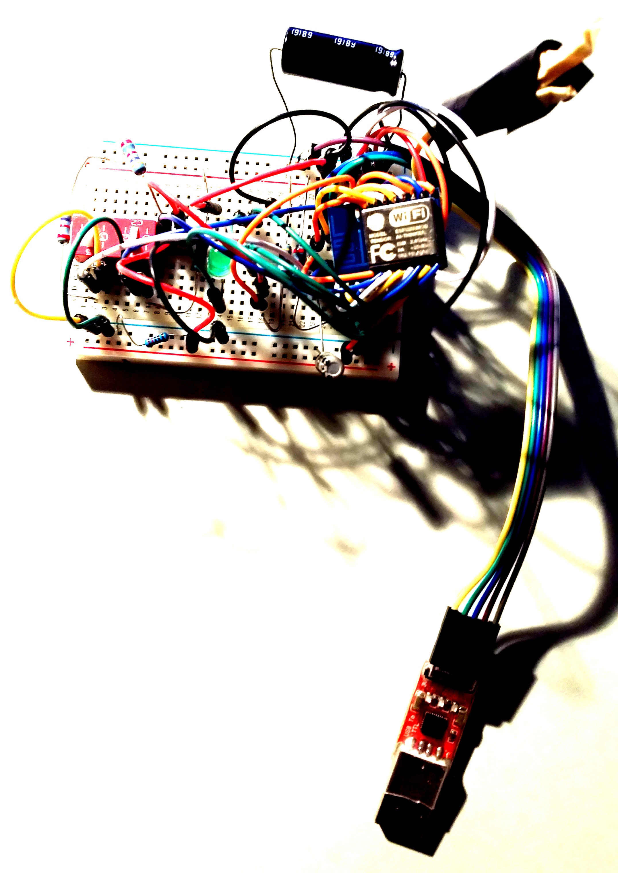
Disappointed and often frustrated by the poor performance of the setup, my next setup used a copper plated breadboard. The ESP8266 was mounted to the board using thin (28 AWG) bare wires. These wires were soldered between the ESP8266 through-holes and the breadboard pads. This was a vast improvement in terms of stability. I currently have a system that has been running for over 2 weeks now with no resets or system crashes. The real-time data collected with this system is displayed publicly on ThingSpeak for independent verification.
But with this setup, the tiny interface wires require a lot of time to initially assemble.
That’s where this adapter plate really shines…
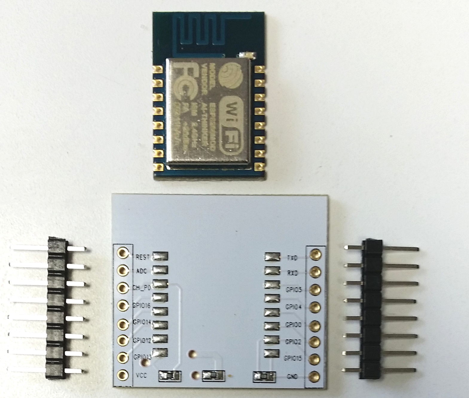
Yes, it really made things easier when I stumbled upon a clean and inexpensive adapter for the ESP8266-7/12 modules. For just 28 cents (AliExpress), you get a PWB plate with pre-soldered mounting pads and a 10k pull-up connected to the chip enable (CH_PD).
A 10K resistor is also included that pulls-down GPIO15 to ground. This resistor is way to large to be of any value for that purpose. For proper boot operation, you must add a connection between GPIO15 and ground.
Finally, the fix is in – the pin labels for GPIO4 and GPIO5 have been corrected on this plate. No more confusion for that until now overlooked ESP8266-12 module design error.
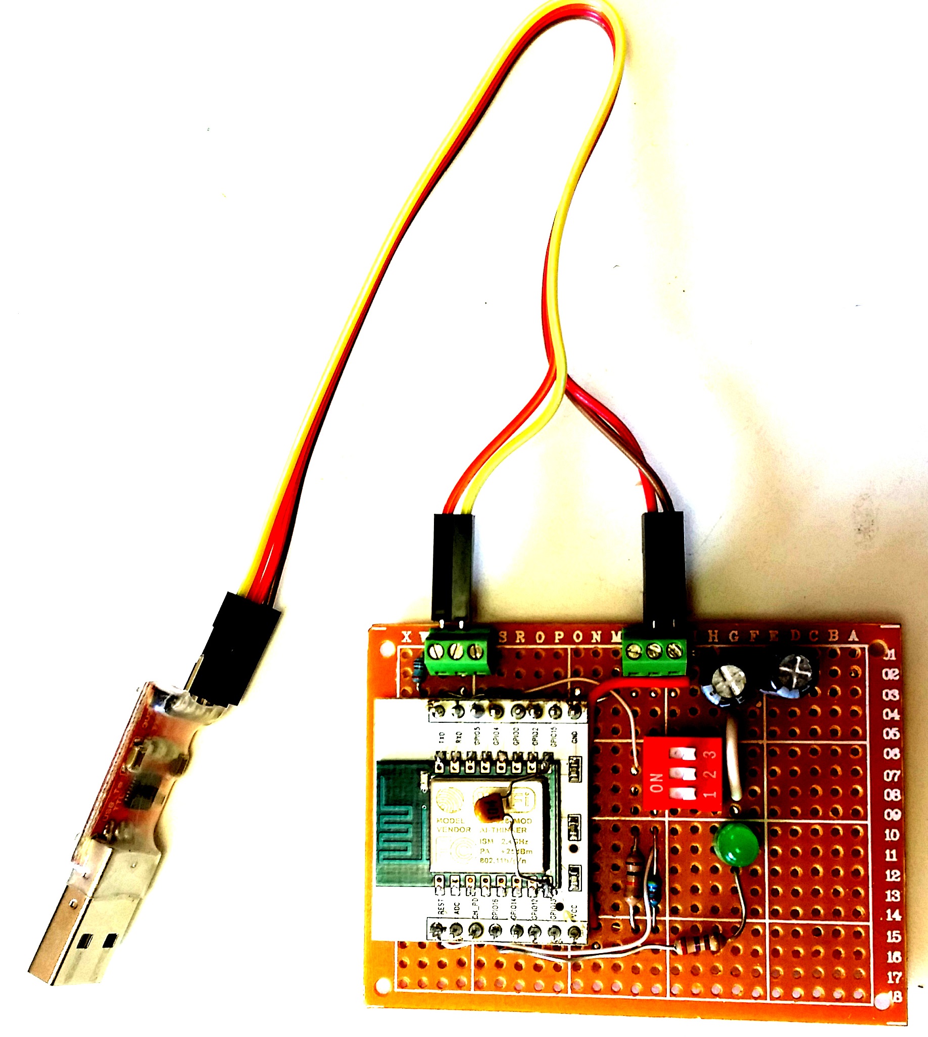
The circuit has come together quite nicely. So far, it has proven to be a very dependable configuration. Boots without errors and flashes reliably the first time, every time. We shall see if this remains true as more the flash cycles are performed.
This begs the question… Why not mount all the parts on a plate like this & eliminate the original carrier board?
A few design considerations
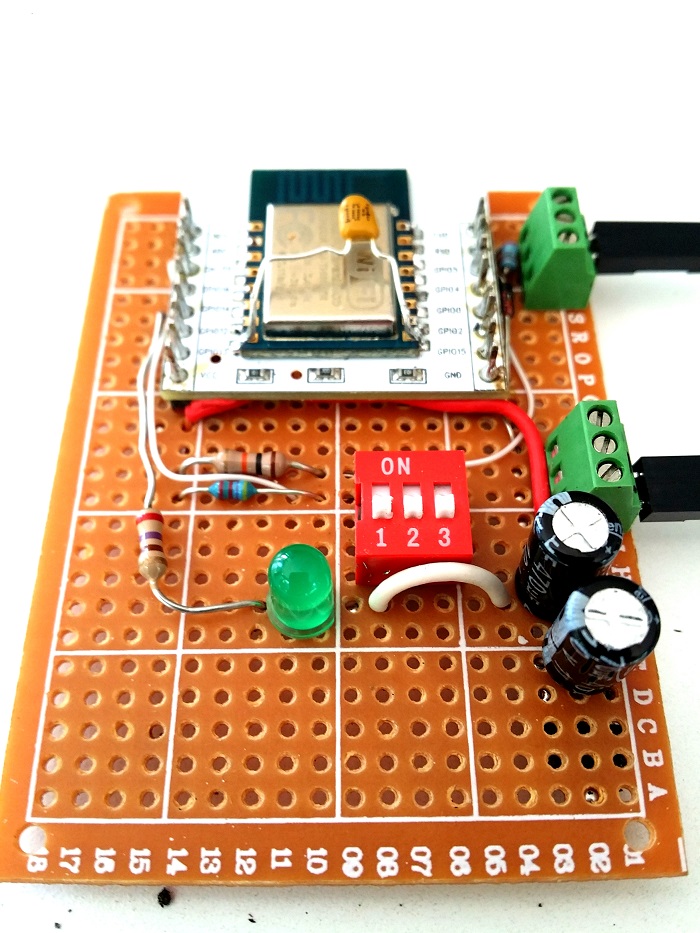
- Notice the 0.1uF decoupling capacitor added close to the ESP8266 assembly. Positioning this essential capacitor there…directly across the ESP8266 VCC and Gnd pins, is absolutely critical for stable operation.
- The header pins were mounted backwards so the longer posts are facing upwards. This will be useful should it be necessary to connect female jumpers directly to any ESP8266 pin.
- The USB to serial adapter cable connections are split between two terminal sections. The right two terminals connect USB 5V and Ground. The left two terminals, serial transmit and receive, are only used when flashing the firmware. Once deployed, the left two terminals are disconnected and the 5V and ground connections are attached to a USB cable. This supports power sourced from a USB wall or car adapter as well as a USB battery.
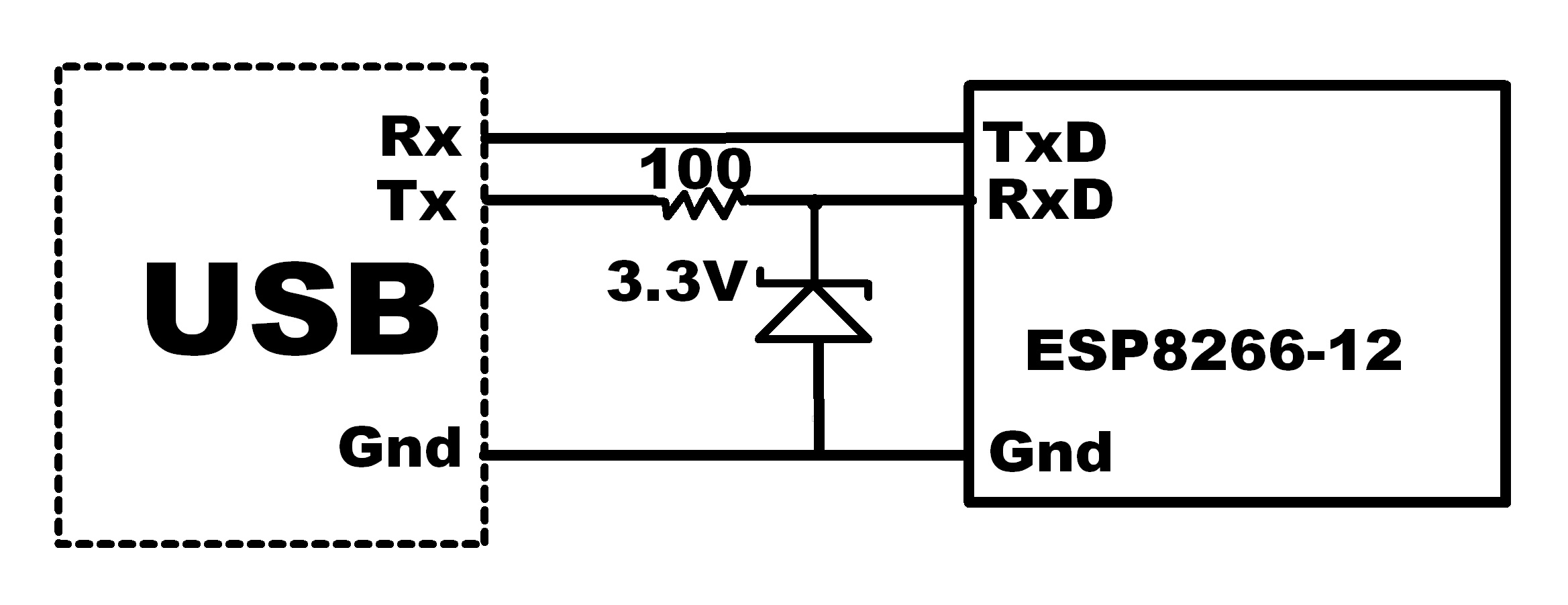
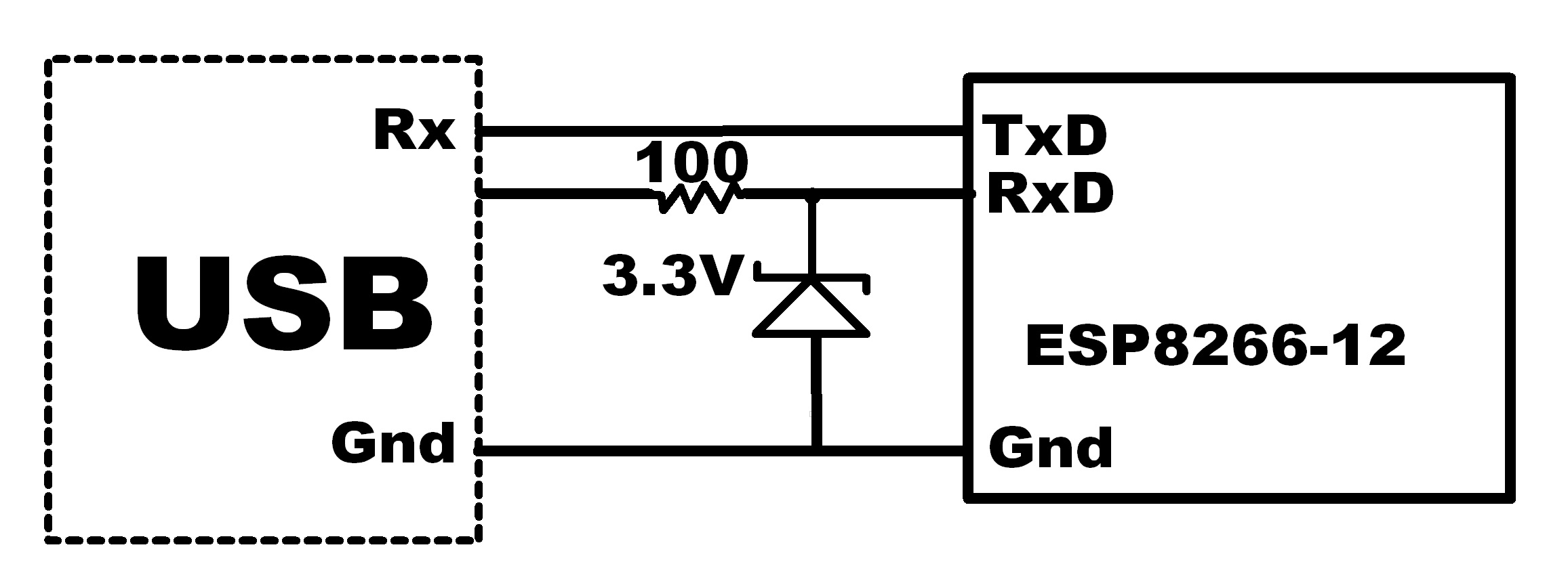
- The ESP serial receive pin has a 100 ohm series resistor included from the serial transmit source. In addition, a 3.3V zener diode clamps the input voltage into the ESP8266. Many ESP8266 users omit these parts. This is not advisable. Exceeding the specified input range will likely degrade the system performance and possibly introduce hard to find latent defects! For long-term reliable operation, these common, readily available components should be included in every interface circuit.
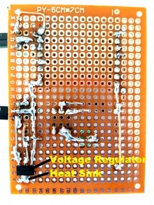
- An AMS1117 voltage regulator converts the 5V to 3.3V for the ESP8266 supply. This is mounted on the breadboard copper side of the breadboard so the heat sink built into the regulator can be soldered to the board.
- To minimize instabilities from voltage ripple, two 470 uF capacitors are used, one across the 5V source and one across the 3.3V ESP8266 supply.
In Conclusion
In my experience, while cheap, feature rich and full of promise, unwanted system resets, flash failures and crashes have been the curse when working with the ESP8266.
But there is hope…
This recently introduced adapter plate, along with the hardware interface features presented here will help mitigate these undesirable outcomes.
Hope you find this information useful…