Archives for ESP8266 WIFI

Mobile Weather Sensors Using ESP8266 – Phase 5: Ant+ Heart Rate Monitor

Adding a Heart Rate Monitor (HRM) wraps up the Mobile Weather Sensor project. To get started, a sensor selection was needed. And since I already have and use a Garmin HRM with a wireless chest sensor, using that same sensor with my setup was the logical choice.

But how to do it?

That was the challenge…

First thing was to figure out how the Garmin unit worked. What sort of RF signal was being sent to my handlebar mounted display? And what message protocol is used? What will it take to interface with my Android, wirelessly?

After some research, I found that the Garmin HRM used an Ant+ interface.

What’s that? Ant+ does look a bit intimidating at first glance. Take a look here.

Fortunately. I was able to boil things down to the bare essentials of what was needed in order for my android phone to receive heart rate data from the sensor. There were several elements needed to make things work…

  • An ant+ radio was needed in the smartphone
  • The ant+ API works directly with a native android app. But since the Weather Sensor App uses the Cordova web interface, a method of communication was needed between the Cordova JavaScript code and the native Java code.
  • The phone app needed to automatically detect the HRM and pair with it (like bluetooth).

These modifications to the existing android app integrate the Java Ant+ API, the Heart Rate Monitor and JavaScript.

The Phone Ant+ Radio

Fortunately, my Samsung Galaxy Note 3 has a built-in ant++ radio. But in order to access this interface, an App must be installed from the Google Play Store. It is called ANT+ Plugin Service. It is really simple. There is no App icon to launch. This is how it works…

Once installed, the service is called anytime an App attempts to connect with an ant+ device. My phone is an ancient model, almost two years old now. Many of the newer phone come with this service pre-installed.

this-is-ant

JavaScript to Java Interface

With an interest in portability between android and iOS phones, the Mobile Weather Sensor App has been built with a standard web interface. This presented a problem since the API provided by the ANT+ team supports android native Java (.java files) but not JavaScript.hrm-code

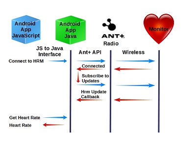
Fortunately, a mechanism has been provided to “extend” the Cordova Web API to communicate with Java code. Here is the source of the information I used to implement the interface between my App and the native code needed to communicate with my heart rate monitor.

First thing to do was to add a reference to this interface code to the project’s config.xml file:

<feature name="HeartRateMonitor">
       <param name="android-package" value="org.apache.cordova.antplus.heartrate.HeartRateMonitorInterface" />
       <param name="onload" value="true" />
</feature>

The first parameter identifies the file containing the feature class object. In this case, the Java code is contained in the file “HeartRateMonitorInterface.java”. The second parameter makes this feature available upon loading the application’s Web view.

But how do we call the Java code from JavaScript?

Here is the Cordova mechanism used to call Java feature “actions” from JavaScript:

cordova.exec(
    callback-if-successful,    //JavaScript Callback function if call 
                               //to Java code was successful
    callback-if-error,         //JavaScript Callback function if call
                               //to Java code was not successful
    "feature name",            //Feature name from config.xml file.
    "feature action",          //Feature action to be executed from 
                               //the .java file
    ["parameter array"]);      //Parameter array to send to Java code

As we shall see, the Java code can return any string back to the JavaScript callback functions. That is how the heart rate received by the Java code is returned JavaScript.

Only two feature actions were implemented to support the heart rate monitor interface:

  1. ConnectHeartRateMonitor – This method establishes a connection between the App and the Heart Rate Monitor
  2. GetHeartRate – This method retrieves the newest heart rate from the Java code.

ConnectHeartRateMonitor is called once at the start of the application while GetHeartRate is called each time the app refreshes the sensor values.

The Java Code

The Java code implements the  class “HeartRateMonitorInterface”. This class contains the following key methods:

  1. execute – This required methods is executed when JavaScript “cordova.exec(()” is called. As noted above, this method only supports two actions.
    1. ConnectHeartRateMonitor makes a call to the Ant+ API method “.requestAccess”. Fortunately, the API does all the hard work of connecting to the Heart Rate Monitor. The Class callback “base_IPluginAccessResultReceiver.onResultReceived” methods is invoked to report the status of the call.
    2. GetHeartRate simply returns the latest heart rate value back to JavaScript.
  2. base_IPluginAccessResultReceiver.onResultReceived is the callback invoked when the ant+ “.requestAccess” method is called. If access was successfully granted, we subscribe to the Heart Rate Monitor Events. Whenever a new event is received, the callback “HeartRateDataReceiver().onNewHeartRateData()” is invoked.
  3. IHeartRateDataReceiver().onNewHeartRateData() receives updates from the heart rate. Upon receipt of a new sensor value, the heart rate is saved to a class variable for retrieval, on-demand, from the JavaScript.

Conclusion

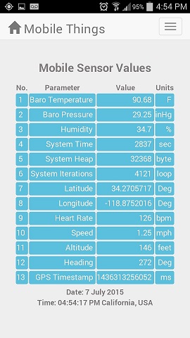
We now have a working application that supports all of the capabilities planned. The Eclipse project files for this application are on GitHub here. The data collected on this mobile application include:

  1. Temperature
  2. Barometric Pressure
  3. Humidity
  4. Speed
  5. Direction
  6. Coordinates
  7. Heart Rate
  8. Altitude
  9. UTC timestamp
  10. Internal ESP statistics

Who knows, there may be more added…

I am looking forward to the coming change of season. With this App and the ESP sensors, I expect to collect some interesting information about significant changes in micro-climate in the span of short distances along the local mountain trails. It will be great to finally quantify what is felt externally as you must peel on and off layers of clothing with changing conditions.

I hope you have found this information is useful to you in your own projects…

Loading

Share This:
FacebooktwitterredditpinterestlinkedintumblrFacebooktwitterredditpinterestlinkedintumblr

Mobile Weather Sensors Using ESP8266

mtbike

Mountain Biking in the local trails in my Southern California home has kept me both reasonably fit while maintaining a close connection with nature. As you roll through many of the trails here, the terrain varies significantly…from the darker shadows of the canyon floors to the wide-open sun exposed ridge-top fire roads. And with these changes there are noticeable variations in the temperature and moisture in the air.

So I got to thinking…

Wouldn’t it be interesting to track these variations as the trail climbs up the mountain face and descends down the other side? Sure, there are gadgets available that do this kind of thing. Like tracking your position, speed, altitude and heart-rate. If you really look around, you might even find one that reports the temperature. Not cheap, but they are available.

Hmmm… Let’s see, can we make a do-it-yourself alternate? A solution that is much cheaper than the cost of a commercially bought product?

This looked like a perfect task for the super low-cost ESP8266 and a few inexpensive sensors. Coupled with a data link to a smartphone, you got a mobile platform tailored to track just about anything. A system that can be tailored to your exact needs. All at a fraction of the cost of a commercially available product, if you can find one meeting the specifications you want.

Here is what I came up with…

My initial design simply collects data samples and saves them to a file on my Android SD Card. This file is then transferred to a PC for visual representation with excel. Later, I intend to add screens to the Android App to display the data on phone. But first, a data collection and storage system was needed.

After thinking about how I wanted to implement these features, the project was broken down into several phases. This post addresses phase 1. Yep, this project is “work-in-progress” and phase 1 is as far as I have gotten…so far. Check back to this blog soon for updates that cover the subsequent elements of this Application as they are developed. Once completed, the “phases” that following will be turned into links.

Phase 1: Mobile Data Collection

Okay, to get started, the scope of the data collection set needed to be defined. First I made a list of the information to collect. While subject to change, initial list includes:

Parameter Units Device
1 Temperature Degrees F ESP8266 Sensor (BMP085)
2 Barometric Pressure in Hg ESP8266 Sensor (BMP085)
3 Humidity Percent ESP8266 Sensor (DHT22)
4 Speed mph Smartphone GPS Sensor
5 Altitude feet Smartphone GPS Sensor
6 Heading Degrees Smartphone GPS Sensor
7 Latitude Degrees Smartphone GPS Sensor
8 Longitude Degrees Smartphone GPS Sensor
9 Heart Rate beats per minute Garmin Ant+ HRM
10 GPS Timestamp ms Smartphone GPS Sensor
11 ESP8266 Run-time seconds ESP8266
12 ESP8266 Heap Bytes ESP8266
13 ESP8266 Iterations Loops ESP8266

The Mobile Smartphone App

The smartphone App is obviously the heart of this project. In this first phase, it must gather data from 3 different sources. But that’s not the only thing to consider. Aside from the Smartphone App, the project also uses an external micro-controller. So the hardware and software design of the ESP8266 system also needs to be developed. But let’s start with the Smartphone App and it’s 3 sources of data.

  1. Phone’s Internal GPS Sensor
  2. ESP8266 Micro-controller
  3. Garmin Heart Rate Monitor

But how do we do it? What do the hardware and software components look like to make this a reality?

GPS Data

My first thought was to add a GPS sensor as an ESP8266 sensor input. But then the obvious hit me… The Smartphone has a built-in GPS Sensor. Why not use it instead of added a redundant capability to the ESP8266 system?

Thanks to the geolocation API included with HTML5, access to the Smartphone GPS data is easy. Starting with the default Native Cordova Android App, the App code (Javascript/jQuery) needed to collect location information from the Phone’s GPS receiver is minimal.

HTML to display the sensor data (simplified, styling excluded):

1. Temperature <p id="tempBaro"></p>
2. Barometric Pressure<p id="presBaro"></p>
3. Humidity<p id="humidity"></p>
4. Speed<p id="Speed"></p>
5. Altitude<p id="Altitude"></p>
6. Heading<p id="Heading"></p>
7. Latitude<p id="Lat"></p>
8. Longitude<p id="Lon"></p>
9. Heart Rate<p id="HeartRate"></p>
10. GPS Timestamp<p id="GpsTimestamp"></p>
11. ESP8266 Run-time<p id="systime"></p>
12. ESP8266 Heap<p id="sysheap"></p>
13. ESP8266 Iterations<p id="sysloop"></p>
Status:<p id="msg">Ok</p>

Javascript/jQuery to collect and update the sensor data display:

 options = {
     enableHighAccuracy: true,
     timeout: 1000,
     maximumAge: 0
 };
 
 //------------------------------------------
 // Functions triggered after page loaded
 //------------------------------------------
 jQuery(window).load(function () {
     navigator.geolocation.watchPosition(onSuccess, onError, options);
 });

 //------------------------------------------ 
 // onSuccess Callback
 //------------------------------------------
 function onSuccess(position) {
     var latt = position.coords.latitude.toFixed(7).toString();
     var long = position.coords.longitude.toFixed(7).toString();
     $("#Lat").html(latt.substring(0, 11));
     $("#Lon").html(long.substring(0, 12));
     $("#Speed").html(position.coords.speed);
     $("#Altitude").html(position.coords.altitude);
     $("#Heading").html(position.coords.heading);
     $("#GpsTimestamp").html(position.timestamp);
     updateWeatherSensorData();
 }
 //-----------------------------------------
 // onError Callback 
 //-----------------------------------------
 function onError(error) {
     //Do nothing (ignore data set) or display message here if an error occurs
     var element = document.getElementById('msg');
     element.innerHTML = 'Failed GPS monitor' + '<br />';
 }


The “options” structure sets the GPS configuration. The “enableHighAccuracy” field must be set to true. This tells the geolocation API to use the phones GPS Sensor. If it is set to false, the API will use the 4G or WIFI connection to determine location. Believe me, you do not want that active, it is very slow. It also will not work on the trail when you are out of cell tower range. The timeout is set to 1 second, setting the maximum time to acquire a location from the GPS sensor. Finally, the maximumAge sets the time to use a cached value before acquiring a new location from the sensor. Setting this to zero forces a new acquisition every time a position change is detected.

Once the Cordova web-based App page (index.html) has been loaded, the geolocation “watchPosition” callback is registered. Subsequently, every time the phones’ GPS sensor detects a change in position, the “onSuccess” callback function is executed. The “onError” callback is run if an error is detected.

navigator.geolocation.watchPosition(onSuccess, onError, options);

You can do anything you want with the data in the “onSuccess” callback. This example simply displays the values on the App window by setting the html for the objects by id to the GPS Sensor measured value. As noted, the next phase of this project will log these values to an SD card file on the Smartphone.

ESP8266 Data

The last line of the “onSuccess” callback executes the function “updateWeatherSensorData”.

 //--------------------------------------------
 //Update WeatherSensor Data
 //--------------------------------------------
 function updateWeatherSensorData() {
     requestURL = "http://192.168.22.1:9703/?request=GetSensors";
     if ( typeof updateWeatherSensorData.timeout == 'undefined' ) {
         // It has not... perform the initialization
         updateWeatherSensorData.timeout = 0;
     }
     //Get Weather Sensor Value
     $.ajax({
         url: requestURL,
         error: function(error){
             if(updateWeatherSensorData.timeout++ <10) {
                 setTimeout(updateWeatherSensorData, 1000);
             }
             else {
                 updateWeatherSensorData.timeout = 0;
             }
         },
         success: function(thedata){
             $("#tempBaro").html(thedata.B_Temperature);
             $("#presBaro").html(thedata.B_Pressure);
             $("#humidity").html(thedata.DH_Humidity);
             $("#systime").html(thedata.SYS_Time);
             $("#sysheap").html(thedata.SYS_Heap);
             $("#sysloop").html(thedata.SYS_Loopcnt);
             updateWeatherSensorData.timeout = 0;
         },
         timeout: 7000 // sets timeout to 7 seconds
     });
 }


The updateWeatherSensorData() function makes an AJAX request to the ESP8266 to return the current sensor values and status in JSON format. Just as with the GPS Sensor data, these values are simply used to set the html for the applicable displayed objects by id.

Heart Rate Monitor Data

A placeholder has been set in the code to collect heart rate monitor sensor data. While I have used Apps that interface with an external heart rate monitor using ANT+ and therefore know it is possible, I have have not accessed this interface in my own App…yet. So, not to hold up the initial release of this project, the Heart Rate Monitor data is planned to be added in Phase 5 using the ANT+ for Android API.

ESP8266 Configuration

The ESP8266 hardware interfaces to just two sensors for this initial design:

  1. BMP085 – Temperature and Pressure Sensors
  2. DHT22    – Temperature and Humidity Sensors

After many revisions from experience using the ESP8266, the hardware for Phase I of this project is configured as shown in the following schematic:

ESP8266-mobile-schematic - Phase 2
The basic ESP8266 framework is shown on the left side of the schematic with the two sensors on the right. Refer to the following posts for more information about the operation of this circuit:

The ESP8266 code for this project is very straight-forward. It consists of a simple web server, with the module operating in access point (AP) mode. The SSID has a fixed value of “ESP8266N4” and responds to the hard-coded IP: 192.168.22.1 on port 9703. These, of course, can be set to any value or even configured at run-time through the serial or initial web server default value. However, this example sticks with the hard-coded values since this system will only be paired with a single Smartphone.

The web server responds to a request for sensor values and status with a JSON string that can be easily parsed with an AJAX call.

Request URL:

http://192.168.22.1:9703/?request=GetSensors


JSON string returned:

{
"B_Pressure":"29.24",
"B_Temperature":"79.34",
"B_Altitude":"555.0",
"DH_Humidity":"34.7",
"DH_Temperature":"69.1",
"SYS_Time":"38",
"SYS_Heap":"32368",
"SYS_Loopcnt":"10",
"SYS_WifiStatus":"255",
"SYS_WifiRecon":"0",
"SYS_WifiMode":"2"
}


The code is based on the IoT_Demo example included in the EspressIf SDK. This project uses SDK Version 1.1.1. The latest version as of this post (1.2.0) should also work but I have not tested it with my code yet.  The ESP8266 source code for Phase I of this project is available on GitHub here.

Mobile App Screen Display

The current App GUI display for Phase I of this project exhibits 13 values.

Mobile Sensors

 This GUI includes CSS styling which takes advantage of the responsiveness of bootstrap. The source code for Phase I of this project is available on GitHub here.

Operation

Once the ESP8266 schematic has been built and the SDK based code has been installed, the ESP8266 is ready. The Android Application should also be installed on the target SmartPhone.

First, power up the ESP8266 from a 5 VDC source. The schematic includes a 5V to 3.3V converter, so I typically use a USB wall source or portable battery. Then you go to the phones WIFI configuration screen and select the ESP8266, which has an SSID of “ESP8266N4” in this example. This will connect the SmartPhone to the ESP8266 so sensor data can be read on demand.

Now start up the Android App. The data will update live, typically at a rate of at least once every second. Go ahead, walk around with the phone and observe the GPS Lat and Long values change. You can also put a finger on the barometric pressure sensor and see a change in the temperature value reported on the display.

Conclusion

We now have a working mobile application that collects sensor data and displays it on the smartphone screen. Using a USB battery with 5000 ma-hours or more, the system can easily move with you, secured in a backpack, fanny-pack or even in your pocket. Stay tuned for the next phase – Periodic logging of these data packets to a file; coming soon…

One final note: While this example uses an Android phone, the Cordova platform used is largely platform independent. While I am not familiar with iOS development, it should be a relatively simple task to adapt this application to work with an iPhone with little or no change to the code.

Hope you find this information useful…


Loading

Share This:
FacebooktwitterredditpinterestlinkedintumblrFacebooktwitterredditpinterestlinkedintumblr