Remember the movie “Groundhog Day “? Original Saturday Night Live cast member Bill Murray re-lives Groundhog Day over and over again. And still again. Kinda like the ESP8266 when it repeatedly resetting… Nothing you try makes a difference!
If you have worked with the ESP8266 for any length of time, you have undoubtedly experienced the endless resets on power-up. The looping message occurs at about 5 second intervals, which seems to be the default internal watchdog timer time-out period. The message, at 115200 baud, looks something like this:
ets Jan 8 2013,rst cause:4, boot mode:(3,7)
wdt reset
load 0x40100000, len 30000, room 16
tail 0
chksum 0x67
load 0x3ffe8000, len 2556, room 8
tail 4
chksum 0xb7
load 0x3ffe8a00, len 3080, room 4
tail 4
chksum 0x59
csum 0x59
r”
I have yet to come across a definitive explanation for this behavior.
Is this the boot-loader?
The core firmware?
Perhaps a chip defect?
From what I have experienced and read from other users, there are two likely hardware causes that makes logical sense:
- Inadequate power supply interface
- A flash chip failure.
In order to prevent resets, you must include the following three features in the power source to the ESP8266.
- Sufficient current. A regulated 3.3V source of at least 500ma is essential. Aside from the 300ma peak current needs of the ESP8266, it is essential to also consider the current requirements for other components you have – like the sensors and controls in your circuit.
- A large capacitor (suggest using 470 uF) across the Vcc to Gnd rails on your breadboard or PCB is a vital ingredient that will minimize reset inducing voltage fluctuations.
- A 0.1 uF decoupling capacitor across the ESP8266 Vcc to Gnd inputs very close to the pins (within 1/2 inch). DO NOT SKIP THIS COMPONENT! This cheap yet often overlooked component, when missing, is the root cause of ESP8266 resets.
Even with these power supply precautions, we know the flash chip (25Q40) used with many of these ESP8266 module is of low quality and fails after only a few flash cycles. Perhaps sending the code somewhere that it never returns from. Triggering the watchdog timer to reset the unit.
I currently have some replacement flash chips on order and shall see if replacing that chip does indeed remedy the unwanted power-up resets. Unfortunately, my ESP8266-12 (-7 also) has a metal shield over the active components, including the flash chip. This will have to be removed in order to gain access to the memory chip. Removing the shield will require a heat gun—and may very well damage the ESP8266 component. That will be done as last resort, when the reset loops appear to be a permanent condition, rendering the module a “brick”.
But for me, I have not had either of my 2 prototyping ESP8266 assemblies fall into a non-repairable reset loop state yet. If the power supply measures noted above are in place, but you are still experiencing resets, here are a few steps I have been taking with some success to bring back to life an ESP8266 stuck in a ‘Groundhog Day’ reset loop:
Note: Since the entire ESP8266 module is so cheap, if you do not wish to invest your precious time in reviving your module, simply chuck it and start again with another unit. Otherwise, read on, here are 4 methods to correct an ESP8266 stuck repeating reset loops endlessly…
1. Check your connections
This seems obvious. But I have not seen this to be a problem with other MPUs, like an Arduino, Spark Core and even PIC processors.
But my first two ESP8266 set-ups use a standard solder-less breadboard. I have heard that the ESP8266 is very sensitive to intermittent connections, and the solder-less breadboard is not recommended. And sure enough, it has been a problem in my setup. While I have since switched to use soldered contacts on a prototyping vector-board, I am still using the two original breadboards for initial testing. Using these units to limit the flash cycles on the more permanent soldered set-ups.
I have already flashed these 2 initial units a couple hundred times, and counting…
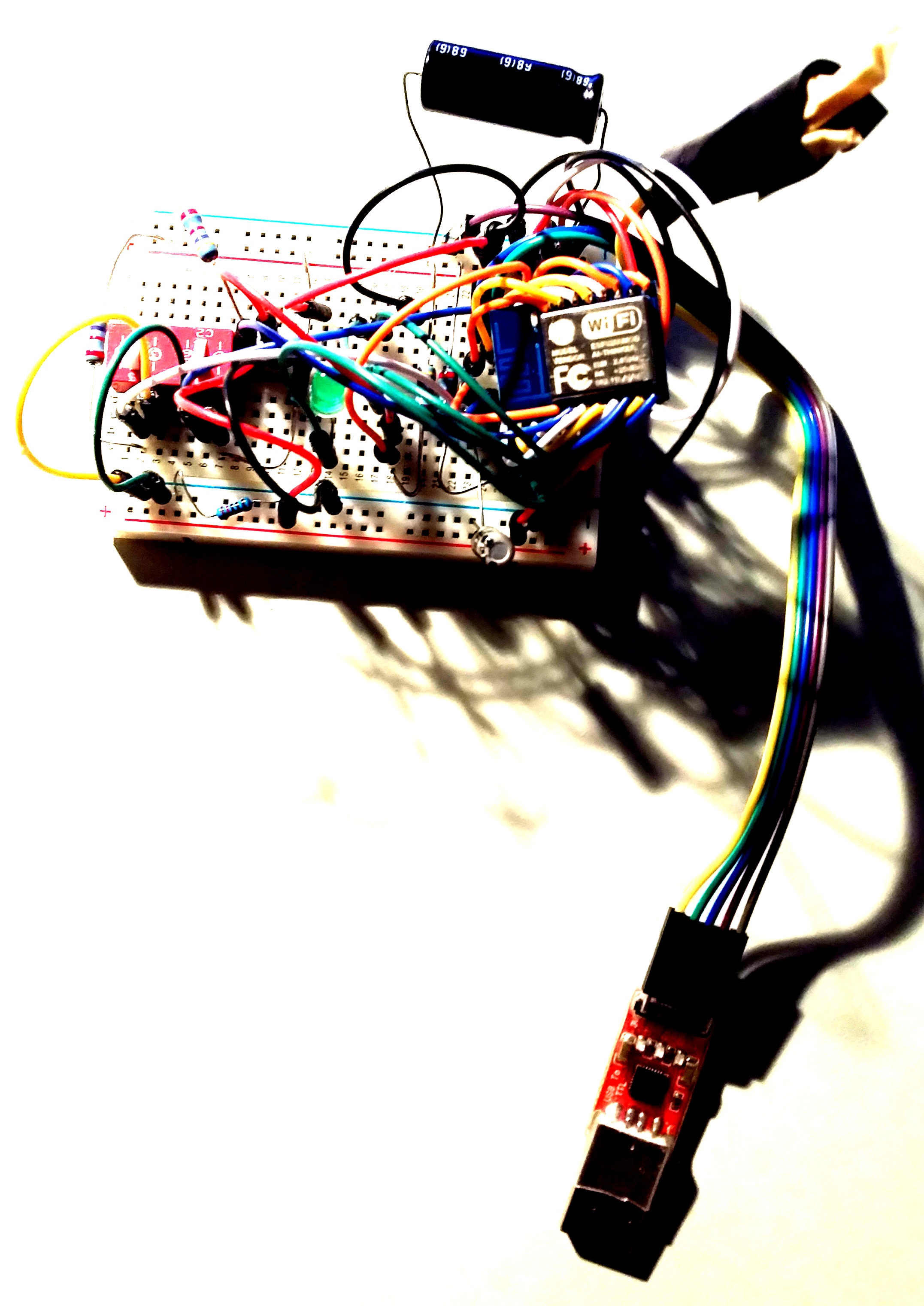
Solder-less breadboard set-up
After many frustrating and unsuccessful attempts to revive my original setup out of reset purgatory, I made a final inspection of the jumpers and found a few of them only partially engaged.
After securing all the connections again…
The phoenix rose from the ashes. Yes, I had just about given up on this unit And now, the next flash successfully restored the set-up out it’s reset loops. The module was spared the life threatening heat gun!
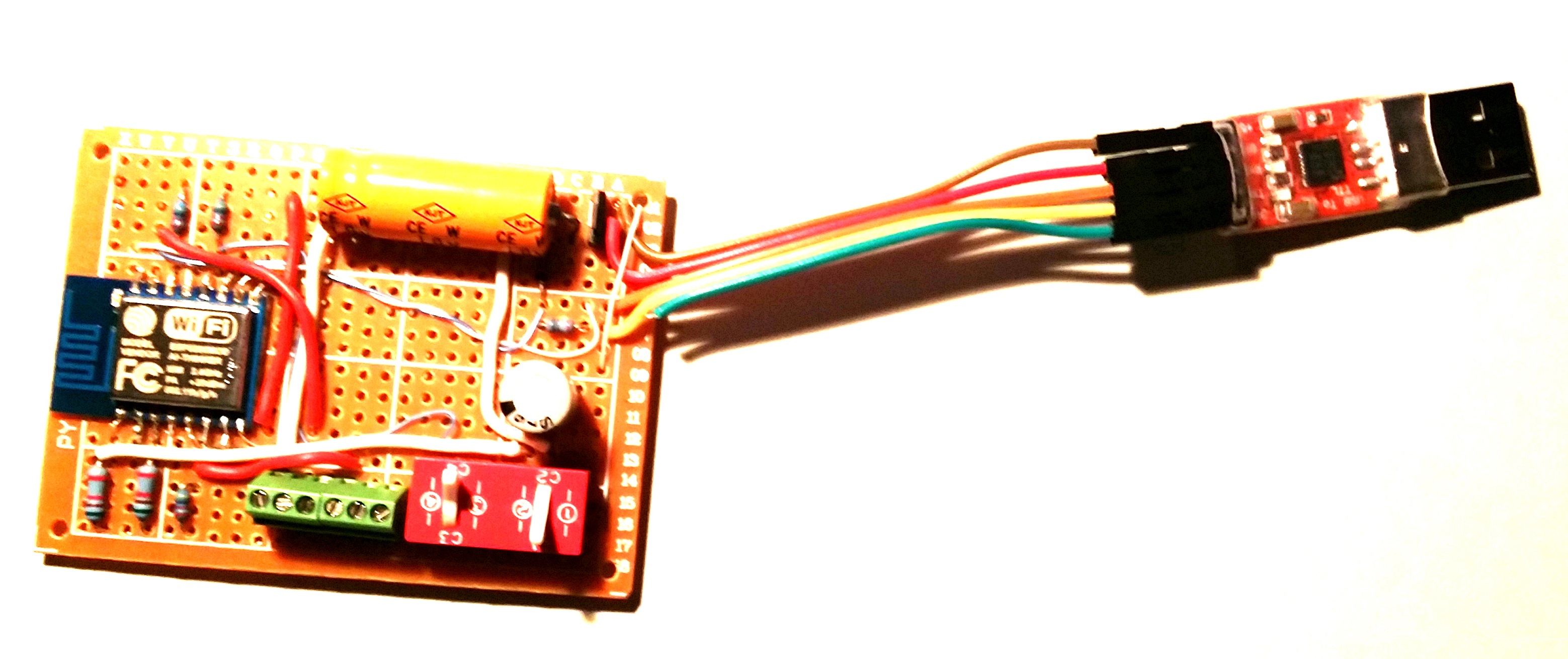
Soldered Printed Circuit Board set-up
2. Clear the memory
Along with securing connections, flashing some of the original binaries back into the module has always worked for me to clear the reset problem, so far. As I have already mentioned, it appears that the code gets stuck somewhere that it never returns from, resulting in a wdt reset. This would seem to be as result of corrupted memory. So clearing the flash memory, if possible, should correct the endless reset condition.
Here is what I have found to work:
2.1 Flash AT command set
Flash the ESP8266 with original AT command binary. In case you do not have the flasher, one place to get it: https://drive.google.com/file/d/0B3dUKfqzZnlwVGc1YnFyUjgxelE/view
Restarting the module in normal mode (GPIO2 HI) should result in a 115200 baud start-up message ending with “ready”. And it should respond to the “AT” command with “OK”.
If so, sweet! –-you are good to go.
But it is not always resolved that easily. Sometimes you got to dig deeper. If, your start-up message ends with “jump to user1” and then stops, additional steps will be needed to restore the module.
2.2 Flash blank.bin
Flashing the blank.bin file, which comes with the nodemcu flasher program, is another method to clear the memory. Using the nodemcu flasher, flash the 4K blank.bin to the following 5 starting addresses:
0x00000, 0x01000, 0x40000, 0x7c000, 0x7e000
Then repeat “2.1 Flash AT command set” above.
2.3 Flash blank to the entire 512 kbytes
I have also created a 512 kbyte version of the blank.bin file to clear the entire flash chip. After flashing this file to 0x00000, the entire flash memory address space is cleared.
After clearing the entire flash chip, I have found it necessary to flash the 4 files in the following zip.
https://developer.mbed.org/media/uploads/sschocke/esp_flasher.zip
Once this is complete, again, repeat “2.1 Flash AT command set” above.
3. Replace the flash memory chip
When all else fails, replace the flash memory chip. This involves soldering to remove the faulty 8-pin device and replacing it with a new one. While I do not have a known source to recommend, there are many to choose from on Aliexpress.com. Like the ESP8266, the flash chips are inexpensive, but there is no way to know for sure about the quality. At a minimum, read the reviews from other buyers before placing your order.
4. Software design considerations
There have been problems experienced that could not be overcome using the nodeMCU/lua and SDK development environments. I will write a blog post soon to document those issues. So the following considerations use the Arduino IDE, which is the only development IDE that has been both effective and reliable in implementing my program requirements at this time…
I have yet to find any information that provides the developer much control over the watchdog timer (wdt). The API simply allows you to enable/disable the timer and to “feed” it. I assume “feed” resets the timer although I have not found any documentation to support that assumption. I have found the following steps necessary to eliminate my IoT software application induced resets:
-
The wdt is enabled by default. It should be enabled during normal application operation. If it is disabled in software, instead of resetting, the ESP8266 will halt when a wdt timeout occurs.
-
It is important to return control to the processors periodically. This is done using the yield() or delay() statements. For example, sensor readings requiring more that 0.5 seconds to complete should be followed by a yield() or delay().
-
In addition to yielding control, I have found it necessary to “feed” the wdt periodically to prevent time-consuming tasks from tripping a wdt reset.
Hopefully this helps someone who has struggled with unwanted module resets.