ESP8266 : An IoT System on Chip

Expanding ESP8266 ADC 1 VDC range

An obvious weakness of the ESP8266 is the limited capability of it’s single ADC input. At best, the voltage range is 0-1 Vdc. While coupling an Arduino module to the ESP8266 solves this problem, is does introduce significant data acquisition delays for the Arduino-to-ESP8266 communication. A preferred solution uses the ESP8266 without requiring an additional processor.

The method presented here adds 4 ADC inputs, each supporting voltages from 0-5V. In addition, one true DAC output is available to replace the PWM feature used for that purpose.

And no additional processor is required.

This is a very inexpensive addition, requiring hardware that acquired for approximately 1 USD.

ESP8266 ADC Range Improvement

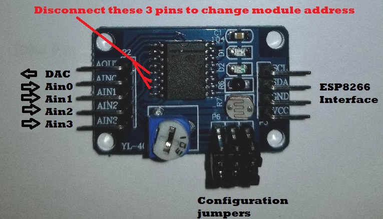
The enhancement is achieved by adding an external i2C bus ADC device to the ESP8266 system. This module, PCF8591, was added to my project recently, purchased from Ali-Express for 93 cents. It sports 4 ADC channels, one DAC channel, a potentiometer, thermister, and a photo-sensor. But for my needs, I have disabled the additional components and use it strictly as a 4-channel ADC.

The device uses an i2C bus, which requires 2 digital pins (any two) to operate.

There are two limitations I discovered while testing this module, neither of which adversely impact it’s functionality in my application.

  1. The ADCs and DAC are 8-bit devices. This results in a somewhat course resolution of 19mV-per-bit when using a 5V reference.
  2. The DAC range is linear 0-4Vdc, but compresses beyond that and tops out at 4.25Vdc.

Even with these constraints, I was still pleased to have the capability of measuring voltages 0-5V. This was a huge improvement over the ESP8266 native 0-1Vdc ADC.

The ADCs can be used single-ended (4 channels) or differential (2 channels), an added capability which allows you to measure signals with a common-mode voltage. Changing the ADC mode is a simple matter of changing the control byte when setting up the ADC for a measurement. As you will see in the sketch below, single-ended measurements are made using the control bytes:


  1. #define PCF8591_ADC_CH0 0x40 //Measure Ain0 single-ended at CH0
  2. #define PCF8591_ADC_CH1 0x41 //Measure Ain1 single-ended at CH1
  3. #define PCF8591_ADC_CH2 0x42 //Measure Ain2 single-ended at CH2
  4. #define PCF8591_ADC_CH3 0x43 //Measure Ain3 single-ended at CH3

Other options, if desired, would expand the set of control bytes:


  1. #define PCF8591_ADC_CH0 0x40 //Measure Ain0 single-ended at CH0
  2. #define PCF8591_ADC_CH1 0x41 //Measure Ain1 single-ended at CH1
  3. #define PCF8591_ADC_CH2 0x42 //Measure Ain2 single-ended at CH2
  4. #define PCF8591_ADC_CH3 0x43 //Measure Ain3 single-ended at CH3
  5. #define PCF8591_ADC_DIFF_CH0CH3_CH0 0x50 //Measure Ain0-Ain3 differentially at CH0
  6. #define PCF8591_ADC_DIFF_CH1CH3_CH1 0x51 //Measure Ain1-Ain3 differentially at CH1
  7. #define PCF8591_ADC_DIFF_CH2CH3_CH2 0x52 //Measure Ain2-Ain3 differentially at CH2
  8. #define PCF8591_ADC_MIXED_CH0 0x60 //Measure Ain0 single=ended at CH0
  9. #define PCF8591_ADC_MIXED_CH1 0x61 //Measure Ain1 single=ended at CH1
  10. #define PCF8591_ADC_MIXED_CH2_CH3 0x62 //Measure Ain2-Ain3 differentially at CH2
  11. #define PCF8591_ADC_DIFF_CH0CH1_CH0 0x70 //Measure Ain0-Ain1 differentially at CH0
  12. #define PCF8591_ADC_DIFF_CH2CH3_CH1 0x71 //Measure Ain2-Ain3 differentially at CH1


ADC Module Interfaces

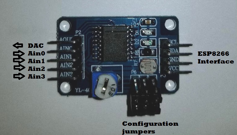
The ESP8266 interface requires 4 signals:

  1. Vcc (5 Vdc, before the 3.3 Vdc regulator)
  2. Gnd (Ground)
  3. SDA (Any ESP8266 Digital pin – GPIO4 in this example)
  4. SCL (Any EAP8266 Digital pin – GPIO2 in this example)

The jumper pins (P4-P6) are removed for 4-channels ADC configuration.

Here is the minimal Arduino sketch I used to test this ADC. As you can see, the ADC read code can easily be included in a more complex sketch.


  1. #include "Wire.h"
  2. #define PCF8591 (0x90 >> 1)
  3. #define PCF8591_DAC_ENABLE 0x40
  4. #define PCF8591_ADC_CH0 0x40 //Measure Ain0 single-ended at CH0
  5. #define PCF8591_ADC_CH1 0x41 //Measure Ain1 single-ended at CH1
  6. #define PCF8591_ADC_CH2 0x42 //Measure Ain2 single-ended at CH2
  7. #define PCF8591_ADC_CH3 0x43 //Measure Ain3 single-ended at CH3
  8. #define SDA 4
  9. #define SCL 2
  10. byte adcvalue0, adcvalue1, adcvalue2, adcvalue3;
  11. byte dac_value=0;
  12. byte adc_value;
  13. void putDAC(byte dac_value)
  14. {
  15. Wire.beginTransmission(PCF8591); //Calls the 8591 to attention.
  16. Wire.write(PCF8591_DAC_ENABLE); //Send a DAC enable word.
  17. Wire.write(dac_value); //Send the desired DAC value (0-255)
  18. Wire.endTransmission();
  19. }
  20. byte getADC(byte config)
  21. {
  22. Wire.beginTransmission(PCF8591);
  23. Wire.write(config);
  24. Wire.endTransmission();
  25. Wire.requestFrom((int) PCF8591,2);
  26. while (Wire.available())
  27. {
  28. adc_value = Wire.read(); //This needs two reads to get the value.
  29. adc_value = Wire.read();
  30. }
  31. return adc_value;
  32. }
  33. void setup()
  34. {
  35. Wire.begin(SDA,SCL);
  36. Serial.begin(115200);
  37. putDAC(0);
  38. Serial.println("dac,ain0,ain1,ain2,ain3");
  39. }
  40. void loop()
  41. {
  42. adcvalue0 = getADC(PCF8591_ADC_CH0);
  43. adcvalue1 = getADC(PCF8591_ADC_CH1);
  44. adcvalue2 = getADC(PCF8591_ADC_CH2);
  45. adcvalue3 = getADC(PCF8591_ADC_CH3);
  46. Serial.print(dac_value++);
  47. Serial.print(",");
  48. Serial.print(adcvalue0);
  49. Serial.print(",");
  50. Serial.print(adcvalue1);
  51. Serial.print(",");
  52. Serial.print(adcvalue2);
  53. Serial.print(",");
  54. Serial.print(adcvalue3);
  55. Serial.println();
  56. putDAC(dac_value);
  57. delay(100);
  58. }

This simple sketch configures the I2C library to attach to ESP8266 GPIO2 and GPIO4 and loop through a sequence of setting the DAC and reading all 4 ADC channels. For this setup, the DAC output is connected to all 4 ADC inputs and jumpers P4-P6 are removed. As one would expect, for each DAC setting, identical ADC values are measured for all 4 ADCs. But there are some deviations from the DAC setting:

DAC Limitations

The ADC measured values deviate from the DAC setting by no more than 1 bit (~ 20mV) from 0-2 Vdc. This deviation increases to 4 bits around 4 Vdc, with the DAC output topping out at about 4.2 Vdc.

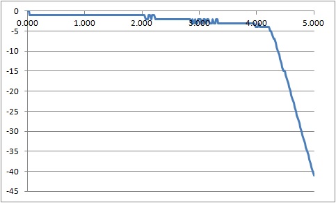
From this we can conclude that the DAC has a functional range from 0-4 Vdc with an error no greater than 4 bits (80mV). Not super accurate, but it is adequate for many applications.

I measured the ADC output with a DVM (digital voltmeter) to confirm the DAC output never exceeded 4.2 Vdc.

ADC Voltage Range

And to confirm the ADC has a full range of 0-5VDC (0-255 byte value), I applied 5 Vdc to one of the Ain inputs and verified the measure value as 255 (5 Vdc). I also used the built-in potentiometer to swing the ADC measurements between 0 and 255 (0-5 Vdc). With a slight modification to the sketch to display the ADC readings from the potentiometer (Ain3) in Vdc, we observe good correlation between the applied voltage and the ADC measurement.

Great!

This confirms the ADC can read voltages over the full 0-5 Vdc range.

Expanding the Channels

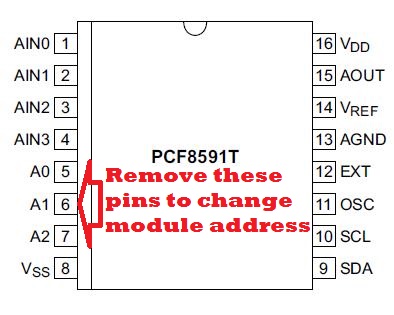
The PCF8591 ADC has 3 programmable address lines which makes it possible to expand the ADC channel count from 4 to 32. Even better, this still only requires 2 ESP8266 digital (GPIO) channels as the control pins would all be connected in parallel.

But there is a catch with the XL-40 carrier module that holds the PCF8591. The 3 address lines are hard-wired to ground. So, to expand the channels, you would need to cut the traces (lift the pins) to set a different address for each added module in your ESP8266 configuration.

No impossible, but you have to be careful not to overheat the device when desoldering the pins.

In Closing

Here is a low-cost (1 USD) addition to your ESP8266 setup that expands the ADC capability to 4 channels with the bonus of a real DAC output. While the DAC is limited to a 0-4Vdc range, you have the full 0-5 Vdc available for analog measurements with reasonable accuracy.

Hope you find this a useful addition to your projects.


Loading

Share This:
FacebooktwitterredditpinterestlinkedintumblrFacebooktwitterredditpinterestlinkedintumblr

Alexa, Ask ESP8266 for Temperature Readings

Uttering Alexa voice commands to turn your ESP8266 connected device on or off is cool. There is plenty of information readily available explaining how to make that happen.

But what a custom command?

Like having Alexa tell you something unique. Using data gathered by reading your specific IoT device sensors?

Such as ESP8266 measured values that change over time.

For example, temperature or other weather sensors.

Having the ability to interact verbally with your IoT device in this manner opens up a wide range of possibilities. Yet, as I discovered, information on this topic was more challenging to find with a google search.

So here is how I did it.

And so can you.

The Problem

What is needed is a method of converting your verbal request into a command that can be sent to your ESP8266 (or other IoT device) to get the requested information, and to return the information to Alexa in a format that she can read back to you.

The solution presented here uses the Amazon Web Services (AWS) to do all the voice interfacing with Alexa, Things Speak as a repository for the ESP8266 sensor data, and a VPS CRON script to move the sensor data from the ESP8266 to Things Speak.

You might wonder why a VPS and Thing Speak are used. Why not communicate directly with the ESP8266 from the AWS Lambda Function?

Truth is, you can cut out these intermediate steps. But for security, I have added this layer to hide my IoT credentials within my heavily fortified Virtual Private Server (VPS). But do not be concerned, as you will see, this does not make the system overly complicated.

System Diagram

Test Scenario

We start with a voice command: “Alexa, ask ESP8266-12 for the indoor temperature”

Alexa responds with: “The indoor temperature is 73.2 degrees”

So what just happened?

Since we are dealing with the Amazon Echo device, Amazon lingo is needed (bold).

The voice command was received by the Amazon Echo device and recognized as an Alexa skill.

Invocation of the skill triggered the Lambda function which, in-turn, sent a request to ThingSpeak for the current ESP8266 sensor readings,

The readings returned were passed back to the Alexa skill which recites the values of the temperature sensors.

Implementation

We need three components to make this system function as intended.

Data Source (ESP8266 Sensor Data)

  • From ThingSpeak Channel or
  • Directly from ESP8266

Amazon Skill to convert your voice to a command to retrieve the requested information

Amazon Lambda function to receive the Skill request, query for the requested information and return a reply to the Amazon Skill

Let’s do it…

You will need to setup two accounts with Amazon, If you do not already have these accounts, create them now. No worries, they are FREE:

Create Amazon Developer Account (For Alexa Skill)

Start by pointing your browser to:

https://developer.amazon.com/

Select “Sign In” located on the page’s top-right header:

Next, select the “Create your Amazon Developer Account” button

Follow the instructions to create your free Amazon Developer Account

Create free AWS account (For Lambda Function)

Start by pointing your browser to:

https://portal.aws.amazon.com/billing/signup#/start

Follow the instructions to create your free AWS (Amazon Web Services) Account

Creating the Alexa Skill

Sign in to https://developer.amazon.com/ and go to the Developer Console.

Select the Alexa tab.

Select “Get Started” Alexa Skills Kit.

Select “Add a New Skill”

Note: The rest of the skill creation can be customized for your needs. It is suggested that you follow along with this guide for your first skill, and customize after getting this example to work. For this example, my publicly shared ThingSpeak Channel is used for the dynamic data source

For the first tab (Skill information), enter:

Name: ESP8266

Invocation Name: e s p eighty two sixty six dash twelve

Then click “Save” at the bottom.

For the Interaction Model tab, enter:

Intent Schema (copy/paste):


  1. {
  2. "intents": [
  3. {
  4. "slots": [
  5. {
  6. "name": "Sensor",
  7. "type": "ESP_SENSORS"
  8. }
  9. ],
  10. "intent": "GetEspInfoIntent"
  11. },
  12. {
  13. "intent": "AMAZON.HelpIntent"
  14. },
  15. {
  16. "intent": "AMAZON.StopIntent"
  17. },
  18. {
  19. "intent": "AMAZON.CancelIntent"
  20. }
  21. ]
  22. }

Custom Slot Types:

Enter Type: ESP_SENSORS
Enter Values:
every
indoor
outdoor
attic

Then click “Add” below the “Enter Values” box..

Now click “Save” at the bottom.

Sample Utterances: GetEspInfoIntent for {Sensor} temperature

Click “Save” at the bottom.

Then click “Next” at the bottom.


Creating the Lambda Function

Sign in to https://portal.aws.amazon.com

Make sure you are on the URL https://console.aws.amazon.com

From the Console, select Services > Compute > Lambda

Click “Create Function”

Click “Author from scratch”.

Enter the following Basic Information:

Name: ESP8266V2

Role: Create new role from templates

RoleName: myEspRole

Policy Templates: CloudFormation stack read-only permissions

Then click “Create Function”

Select Runtime: “Node.js 4.3”

Then paste the following code in the index.js field:


  1. /**
  2. Copyright 2014-2015 Amazon.com, Inc. or its affiliates. All Rights Reserved.
  3. Licensed under the Apache License, Version 2.0 (the "License"). You may not use this file except in compliance with the License. A copy of the License is located at
  4. http://aws.amazon.com/apache2.0/
  5. or in the "license" file accompanying this file. This file is distributed on an "AS IS" BASIS, WITHOUT WARRANTIES OR CONDITIONS OF ANY KIND, either express or implied. See the License for the specific language governing permissions and limitations under the License.
  6. */
  7. /*
  8. This file has been modified under the terms of the above license October 2017
  9. */
  10. /**
  11. * This code is dependant on data retreived from a ThingsSpeak channel
  12. * It is a Lambda function for handling Alexa Skill requests.
  13. *
  14. * Examples:
  15. * One-shot model:
  16. * User: "Alexa, ask ESP8266 for temperature readings"
  17. * Alexa: "Indoor temperature is 75.2 degrees and outdoor temperature is 86.2 degrees"
  18. */
  19. /**
  20. * App ID for the skill
  21. */
  22. var APP_ID = undefined; //OPTIONAL: replace with "amzn1.echo-sdk-ams.app.[your-unique-value-here]";
  23. //var APP_ID = "amzn1.ask.skill.018df58b-9e42-4e0f-927c-fd06ba2edb5b"; //OPTIONAL: replace with "amzn1.echo-sdk-ams.app.[your-unique-value-here]";
  24. /**
  25. * The AlexaSkill prototype and helper functions
  26. */
  27. var AlexaSkill = require('./AlexaSkill');
  28. var https = require('https');
  29. //ThingSpeak Data Access
  30. var channel_id = 33251;                        //ThingSpeak Channel ID
  31. var speak_key = '9VGQ4X79MQJC90RD';            //ThingSpeak Channel Read Key
  32. var p_at,p_ou,p_in;                            //Sensor Readings
  33. // Create URL to retrieve latest temperature reading from my ThingsSpeak channel (JSON format)
  34. var url = 'https://api.thingspeak.com/channels/' + channel_id + '/feed/last.json?api_key=' + speak_key;
  35. /**
  36. * ESP8266 is a child of AlexaSkill.
  37. * To read more about inheritance in JavaScript, see the link below.
  38. *
  39. * @see https://developer.mozilla.org/en-US/docs/Web/JavaScript/Introduction_to_Object-Oriented_JavaScript#Inheritance
  40. */
  41. var Esp8266 = function () {
  42. AlexaSkill.call(this, APP_ID);
  43. };
  44. // Extend AlexaSkill
  45. Esp8266.prototype = Object.create(AlexaSkill.prototype);
  46. Esp8266.prototype.constructor = Esp8266;
  47. Esp8266.prototype.eventHandlers.onSessionStarted = function (sessionStartedRequest, session) {
  48. //console.log("onSessionStarted requestId: " + sessionStartedRequest.requestId + ", sessionId: " + session.sessionId);
  49. // any initialization logic goes here
  50. };
  51. Esp8266.prototype.eventHandlers.onLaunch = function (launchRequest, session, response) {
  52. //console.log("onLaunch requestId: " + launchRequest.requestId + ", sessionId: " + session.sessionId);
  53. handleEsp8266Request(response);
  54. };
  55. /**
  56. * Overridden to show that a subclass can override this function to teardown session state.
  57. */
  58. Esp8266.prototype.eventHandlers.onSessionEnded = function (sessionEndedRequest, session) {
  59. //console.log("onSessionEnded requestId: " + sessionEndedRequest.requestId + ", sessionId: " + session.sessionId);
  60. // any cleanup logic goes here
  61. };
  62. Esp8266.prototype.intentHandlers = {
  63. "GetEspInfoIntent": function (intent, session, response) {
  64. var speechOutput;
  65. var cardTitle;
  66. var sensorSlot = intent.slots.Sensor,
  67. sensorName = "every";
  68. if (sensorSlot && sensorSlot.value){
  69. sensorName = sensorSlot.value.toLowerCase();
  70. }
  71. switch(sensorName) {
  72. default:
  73. case "every":
  74. speechOutput = "Indoor temperature is " + p_in + " degrees" +
  75. " and the Outdoor temperature is " + p_ou + " degrees and " +
  76. "the Attic temperature is " + p_at + " degrees";
  77. cardTitle = "Temperature Readings";
  78. break;
  79. case "indoor":
  80. speechOutput = "Indoor temperature is " + p_in + " degrees";
  81. cardTitle = "Indoor Temperature Reading";
  82. break;
  83. case "outdoor":
  84. speechOutput = "Outdoor temperature is " + p_ou + " degrees";
  85. cardTitle = "Outdoor Temperature Reading";
  86. break;
  87. case "attic":
  88. speechOutput = "Attic temperature is " + p_at + " degrees";
  89. cardTitle = "Attic Temperature Reading";
  90. break;
  91. }
  92. response.tellWithCard(speechOutput, cardTitle, speechOutput);
  93. },
  94. "AMAZON.HelpIntent": function (intent, session, response) {
  95. response.ask("You can say ask ESP8266 for indoor temperature, or, you can say exit... What can I help you with?", "What can I help you with?");
  96. },
  97. "AMAZON.StopIntent": function (intent, session, response) {
  98. var speechOutput = "Goodbye";
  99. response.tell(speechOutput);
  100. },
  101. "AMAZON.CancelIntent": function (intent, session, response) {
  102. var speechOutput = "Goodbye";
  103. response.tell(speechOutput);
  104. }
  105. };
  106. /* -------------------------------------------------------------
  107. * Get all sensors temperatures and return speech to the user.
  108. * -------------------------------------------------------------
  109. */
  110. function handleEsp8266Request(response) {
  111. // Create speech output
  112. var speechOutput = "Greetings, I did not understand what you want. How may I serve you?";
  113. var cardTitle = "Initial Request";
  114. response.tellWithCard(speechOutput, cardTitle, speechOutput);
  115. }
  116. // Create the handler that responds to the Alexa Request.
  117. exports.handler = function (event, context) {
  118. https.get(url, function(res) {
  119. // Get latest sensor data from home IoT SoC
  120. res.on('data', function(d) {
  121. p_in = JSON.parse(d).field1;
  122. p_ou = JSON.parse(d).field2;
  123. p_at = JSON.parse(d).field3;
  124. // Create an instance of the SpaceGeek skill.
  125. var Esp8266_skill = new Esp8266();
  126. Esp8266_skill.execute(event, context);
  127. });
  128. res.on('end', function() {
  129. });
  130. res.on('error', function(e) {
  131. context.fail("Got error: " + e.message);
  132. });
  133. });
  134. };

Now save this function (Click “Save and test”)

Exit out of the “Test” screen and click on the “Triggers” tab

Then click “Add Trigger” and click in the dotted box:

Select “Alexa Skills Kit”:

And click “Submit”.

Now Lets link the Lambda Function to the Alexa skill:

Return to the Alexa Skill developed earlier:

Click Alexa Skills Kit > Get Started

Click on the Name of the Skill created earlier

Click “Configuration”

Click the Endpoint “AWS Lambda ARN” radio button

Paste the ARN from the paste buffer in the “Default” box

Click bottom “Save” button

That’s it!

Now let’s test it…

The next tab on the Alexa Skills page is called “Test”. Select it and scroll down to the “Service Simulator”

Using the “Text” table, simply enter one of the following utterances, click “Ask ESP8266” and verify you get an appropriate “Service Response”:

every temperature
indoor temperature
outdoor temperature
attic temperature

For example, the utterance “attic temperature” should produce the following Service Response in JSON format:


  1. {
  2. "version": "1.0",
  3. "response": {
  4. "outputSpeech": {
  5. "text": "Attic temperature is 49.2 degrees",
  6. "type": "PlainText"
  7. },
  8. "card": {
  9. "content": "Attic temperature is 49.2 degrees",
  10. "title": "Attic Temperature Reading"
  11. },
  12. "speechletResponse": {
  13. "outputSpeech": {
  14. "text": "Attic temperature is 49.2 degrees"
  15. },
  16. "card": {
  17. "content": "Attic temperature is 49.2 degrees",
  18. "title": "Attic Temperature Reading"
  19. },
  20. "shouldEndSession": true
  21. }
  22. },
  23. "sessionAttributes": {}
  24. }

The actual temperature readings will vary, depending on the current temperature in my attic.

You should now be able to invoke this skill using your Amazon Echo using voice commands.

You can verify that this new skill is enabled on your Alexa echo at https://alexa.amazon.com

Select “Skills” and then “Your Skills”. This new skill should be listed and enabled.

The rest of the system has been covered in previous blog posts:

Things Speak Channel:

  • Write values
  • Read Values

Refer to my ThingSpeak Channel

Virtual Private Server (VPS):

  • Read from ESP8266
  • Write to Things Speak

Uses a Linux CRON script scheduled to run at the start of every hour.

See this post: PHP Script to move ESP8266 data

ESP8266 Sensor data source:

  • Read Sensors Continuously
  • Send Sensor Values on request as JSON string

ESP8266 Temperature Sensor Project

In Conclusion

As you can see, you can make the information collected by your IoT device, such as an ESP8266 accessible via audio commands/responses using the Amazon Echo device. The commands and responses can be customized to the exact words you wish to use. This opens up infinite possibilities.

Hope you find this information useful and fun to explore.

Loading

Share This:
FacebooktwitterredditpinterestlinkedintumblrFacebooktwitterredditpinterestlinkedintumblr

MQTT for App Inventor – Adding TLS Security

This article adds TLS security as a connection option to my original MQTT App Inventor project. The addition is relatively straight-forward.  The App already had the ability to configure MQTT connection and message parameters. Adding the TLS option was a simple matter of adding a check-box to the configuration screen and modifying the JavaScript code used to communicate with MQTT.

Here are a few of my past posts for review. They are related to MQTT and TLS connections:

Now lets update the App Inventor project to support TLS connections to an MQTT broker. Since this article only covers the updates needed to support TLS, it is recommended that the initial project article be reviewed in case anything is unclear.

And if you want to jump ahead and have a look at the project, here it is.

Updating the Configuration GUI

Since the choice is binary, that is, we either want to connect using a TLS or a non-TLS MQTT channel, the GUI selection is obvious; a checkbox. This was added to the top of the configuration screen. You can customize the position if desired.

Updating the Configuration File

We use the same configuration file as the original project. Each configuration parameters is stored in this file as a JSON string. The file resides on our target Android device. The checked/unchecked state of our added checkbox gets saves in the JSON object as a “true” or “false” string.

The TLS connection option is added at the bottom of the configuration file (cfg.txt).


  1. {
  2. "mqtt_broker":"yourmqttbrokerdomain",
  3. "mqtt_txtopic":"mqtt_request",
  4. "mqtt_rxtopic":"mqtt_reply",
  5. "mqtt_un":"user2",
  6. "mqtt_pw":"user2",
  7. "mqtt_port":"8083",
  8. "mqtt_clientId":"clientID",
  9. "mqtt_keepalive":"60",
  10. "mqtt_lastWillTopic":"lwt",
  11. "mqtt_lastWillMessage":"closing down....",
  12. "mqtt_lastWillQoS":"0"",
  13. "mqtt_TLS_enable":"true"
  14. }

Updating the JavaScript

The JavaScript used to interface with the MQTT broker is the final but most important element of this update. Just as in the original App, the JSON  string containing the MQTT connection parameters is sent to the JavaScript using the App Inventor “WebViewString” feature.

Just as before, our custom JavaScript behaves as a “Wrapper” server, which communicates with the open-source MQTT 3.1.1 WebSocket API (mqttws31.js). Again, if this is unclear, please review my original project description.

The custom JavaScript code is stored in the file “mqtt_appinventor_paho.html”. Adding the TLS connection option required only one new line of code:


  1.   connectOptions.useSSL = cfgpar.mqtt_TLS_enable == "true";

That is the power of JSON.

The configuration file received via “WebViewString” from the App Inventor App can be parsed by parameter name (cfgpar.mqtt_TLS_enable). If the string is set to “true”, the connect option “useSSL” is enabled. If the string is not set to “true”, then the “useSSL” option is disabled. connectOption.useSSL is built into the open-source MQTT Websocket API.

That’s it!

The updated App Inventor project is accessible on GitHub here.

Testing the Update

When testing this update, it is important to remember to configure the MQTT port to one that is known to support TLS connections.Since this App is designed to communicate with an ESP8266 via an MQTT broker, it is recommended to test the App using the ESP8266 and MQTT broker from these posts:

But if you simply wish to verify the MQTT connection, any MQTT client can be used. My favorite is the web-based HiveMQTT client.

In Closing

There  you have it. Secure TLS MQTT connections in an App Inventor project. Hope you find this feature useful.

Loading

Share This:
FacebooktwitterredditpinterestlinkedintumblrFacebooktwitterredditpinterestlinkedintumblr

ESP8266 SSL/TLS MQTT Connection

Securing your IoT things is critical. MQTT connections are definitely at risk. But simply using username/password combinations for your MQTT connection is NOT secure.

Why not?

Well, even with passwords, everything sent over the Internet is unencrypted…open for any and all prying eyes to see…and possible maliciously manipulate.

Fortunately, we can solve that problem by creating TLS connections for secure MQTT data transfers. And yes, this encryption layer can even be brought to the ESP8266 platform.

But it does come at a cost…a huge bite out  of the limited ESP RAM heap. With grave consequences. I certainly experienced catastrophic results during in my initial attempts. Finally, and after several iterations, the implementation presented here now manages the heap successfully. Using this approach, we achieve the desired results…a  stable, reset-free ESP8266 platform with a secure interface to an MQTT broker.

Cutting to the Chase

At this point, if you would like to jump in without the benefit of additional explanation, please find the code for this Arduino 1.8.2 IDE compiled project here.

Compiler Issue

The first step towards adding TLS to the ESP8266 framework was to access a secure MQTT Broker. Installation of a TLS MQTT Broker was presented in my last post. After setting up the TLS MQTT broker on a VPS host, the next step was to update the ESP8266 IoT platform developed previously to support the secure connection. This required the addition of a new class to the project; WiFiClientSecure. This class supports secure TCP connections.

But I soon discovered the first problem…

You see, the project simply would not compile with the introduction of this class.

Through much research and frustration, I finally discovered the root cause of the problem and better yet, a solution.

As it turned out, one of the compiler flags used by the Arduino IDE was incompatible with the new WiFiClientSecure class library, and had to be   revised. While your computer may have a different path to the compiler options file, mine was located on a Windows 10 PC at:

C:\Users\owner\AppData\Local\Arduino15\packages\esp8266\hardware\esp8266\2.2.0\platform.txt

Here is the line that needs to be changed in order to compile the project:


  1. #OLD: compiler.c.elf.libs=-lm -lgcc -lhal -lphy -lpp -lnet80211 -llwip -lwpa -lcrypto -lmain -lwps -lsmartconfig -lmesh <span style="color: #ff0000;">-lssl</span>
  2. #NEW: compiler.c.elf.libs=-lm -lgcc -lhal -lphy -lpp -lnet80211 -llwip -lwpa -lcrypto -lmain -lwps -lsmartconfig -lmesh <span style="color: #ff0000;">-laxtls</span>

A Heap of Trouble

After a successful compilation and upload to my development ESP8266 hardware, I soon discovered that the TLS connection consumed a huge chunk of the ESP heap (RAM). Somewhere between 12 and 15 kB. This was such a big resource hog that the ESP8266 would reset anytime a TLS MQTT connection was attempted.

And I also discovered that the configuration screen also used a large amount of ESP heap. That was because, even though the page’s HTML was stored in program memory as a constant, it had to be brought into the heap for run-time modifications before the page was rendered.

These two processes, ESP configuration and TLS MQTT connection negotiation were fighting for the same limited heap space. While each process would work on its own, they simply could not both exists at the same time.

So the project was modified to start up in one of two modes:

  1. Configuration Mode – Sets unique ESP8266 operational parameters
  2. MQTT Connection Mode – Connects to TLS Sensor and continuously reads sensors

Start-up Mode

Upon power-up, the ESP8266 had to know which mode to start up in. That would limit the heap usage to the requirements of the selected mode. This was implemented as a EEPROM location that is read in the programs setup() function.


  1. SetSysCfgFromEeprom(); // Set Session Cfg from EEPROM Values

Two EEPROM locations are now used for MQTT initialization.


  1. GetEepromVal(&amp;Param, EEPROM_MQTTSSLEN, EEPROM_CHR);
  2. mqtt_ssl_enable = os_strcmp(Param.c_str(), "true")==0;
  3. GetEepromVal(&amp;Param, EEPROM_MQTTCLEN, EEPROM_CHR);
  4. mqtt_cl_enable = os_strcmp(Param.c_str(), "true")==0;

If MQTT is configured to be enabled (mqtt_cl_enable), then the second parameter (mqtt_ssl_enable) is used to determine whether a TLS connection (sslClient) or a standard connection (espClient) is to be used at ESP8266 startup:


  1. if(mqtt_cl_enable) {
  2. client = mqtt_ssl_enable ? new PubSubClient(sslClient) : new PubSubClient(espClient);
  3. MqttServer_Init(); // Start MQTT Server
  4. }

These two parameters are set within the operational mode that the ESP8266 is currently operating.

Identifying the Start-up Mode

There are two methods to determine which mode the ESP8266 start up running. You can either look at the start-up output from the serial port or query the ESP8266.

Configuration Mode with Web Server:
The start-up output will include the following if the ESP has started up in configuration mode, with the web server running:

ESP8266 IP: 192.168.0.133
ESP8266 WebServer Port: 9705
ESP8266 Mode: Web Server Running – Type = SDK API

Of course, the port and IP values may vary if they are configured differently.

MQTT Mode:
The start-up output will include the following if the ESP has started up in MQTT Mode:

MQTT Rx Topic: mqtt_rx_18fe34a26629
MQTT Tx Topic: mqtt_tx_18fe34a26629
ESP8266 Mode: MQTT Client Running

Note the MQTT topics are provided. These values need to be known in order to communicate with the ESP, which acts like a server for this project.

Start-up Mode Query
The start-up mode can also be determined from the response to a query. This method may be preferred for applications that do not have access to the ESP serial port or are using the serial link for other purposes.

The ESP will not respond if it is not running in the queried mode. For configuration mode, simply enter the configuration URL (or any other valid web server URL). If the ESP responds, it is running in this mode.

Likewise, attempt to send a message to the ESP MQTT  “server”. If is running in MQTT mode if a response is received

Configuration Mode

The configuration screen from the last iteration of this project was modified to add the new MQTT parameters. Just as before, this screen is accessed by entering the ESP8266 IP (or domain name) with it’s assigned web server port with the following suffix :

http://192.168.0.133:9705/config

If you want to switch to the TSL MQTT operating mode at power-up, just check the 2 new boxes, click SAVE, and then RESET ESP8266.

A URL has also been provided to switch modes within your application code:

http://192.168.0.133:9705/?request=MqttSslOn

This will change the EEPROM content to switch modes and reset the ESP8266 so it starts-up in the selected mode.

MQTT Mode

When the ESP8266 starts up in MQTT mode with TLS connection enabled, it will respond to server requests just like it did in the last iteration of this project. And switching back to ESP web server/configuration mode is simply a matter of sending the request in an MQTT message:

/?request=HttpOn

Conclusion

We now have a secure MQTT connection to the ESP8266. Here is the project code link again. And with careful management of the RAM (heap), it will perform reliably. More functionality in this case requires the distribution of tasks between two operating modes which are only loaded in memory when needed. This technique can be used in other cases as well to stretch the capabilities of this amazing little system on a chip (SoC) we call ESP8266.


Loading

Share This:
FacebooktwitterredditpinterestlinkedintumblrFacebooktwitterredditpinterestlinkedintumblr

Continuous ESP8266 Operation

esp8266

Many ESP8266 enthusiasts still struggle with unwanted resets and non-recoverable system crashes. That comes from my recent review of the most often expressed issues noted on-line. After investing significant time with this module, many have simply given up and moved on with other options.

That is too bad…

And while I have written several articles on the subject, I have to admit that my long-term ESP8266 reliability test also failed months ago. But the test had not been revisited. That is. not until now. The problem was that the original tests were using an older, less reliable sketch structure.

Now, with some much-needed improvements, my basic setup now provides a reliable and stable platform for IoT projects. That is the point of this writing. The following information should prove useful for anyone wanting to use the ESP8266 on a 24/7 basis with minimal or no down-time…

Here’s a reference to my past writings on this topic:

4 ways to eliminate ESP8266 Resets

A cleaner ESP8266-12 hardware setup

ESP8266 WIFI dropout-proof connectivity

Past Monitoring the Esp8266 Performance

My original reliability test used a ThingSpeak channel to monitor the ESP8266 performance. This same channel will now be reused to evaluate  the updated sketch structure. The longest run-time recorded during the original test was 28 days. Then, the ESP8266 crashed fatally and could not recover. Yet every 24 hour period  in the 28 day span recorded at least 10 ESP8266 resets. Fortunately, the sketch was structured to recover from a reset. That is, until the fatal crash occurred during day 28.

This Time Should Be Better

The original sketch used polling to check for http server requests. This was executed each loop() cycle. I used this structure based on project examples found on-line. But the design is flawed. A much more reliable approach is to setup a separate event-driven callback function outside the sketch loop() function to respond to http requests. This post presents more detailed description of this http server sketch structure using the ESP8266. Operating in a separate thread, the responsiveness of the callback is not dependent upon the time required to execute the sequential steps in the loop() function.

I also discovered that my USB to serial device was causing frequent ESP8266 resets. It also was failing frequently during sketch uploads.

This was replaced, and then removed once the final sketch was installed. The operating unit now only uses the 5V and Gnd wires from a USB cable.  The 5V is fed through a voltage

regulator to provide the 3.3v for ESP operation.

Monitoring the ESP8266

In this case, the ESP8266 functions as an http server. In addition, it periodically reads any attached sensors. These sensor values are returned as an http reply to a request. The current ESP8266 system time (seconds since the last reset) and the number of WIFI disconnect/reconnections are also returned; all within a JSON string.

So the ESP8266 simply waits for requests and monitors sensors.

I have set up a CRON script, written in php, to request and record the current values from the ESP8266. The script also records the values both to the ThingSpeak channel and a separate mySQL database. This is repeated once every hour, on the hour. A description of this process and the ThingSpeak channel is detailed in this post.

The Results

So far, the ESP8266 has been running continuously for almost 8 days without a single WIFI drop-out or ESP8266 reset. There is no reason to doubt that this system will run indefinitely. That is, until the power company delivers a disruption in service or my internet connection goes down.

uptime

In Closing

I hope this experiment offers encouragement to anyone using the ESP8266 that has been frustrated with unreliable performance. Check back periodically to see how long this module performs with crashing with a reset. Here is a quick link to the ThingSpeak channel monitoring the unit.

2016-Sep-23 Update:

The Santa Ana winds kicked up this afternoon and with rising temperatures,  ACs were cranking everywhere here in Southern California.  This triggered a one-minute power outage which also shut down the ESP8266 after a bit over 8 hours of continuous operation.  A UPS on the ESP8266 per source is needed to prevent this from happening again.

2016-Oct-17  Update:

Five days ago I discovered that the ESP8266 data feed into the ThingSpeak channel was no longer updating values. After some troubleshooting, the root cause was isolated to my 24 port Cisco Ethernet Switch. The problem was not with the switch, but rather one of my devices connected to it. I removed all the connections and re-introduced the essential devices, one-by-one with the system restored to full operational capability. One of the devices was a WIFI access point. This device is used in my home network to extend the range of my WIFI coverage. And that device is what the ESP8266 connects to for network access. Unfortunately, while troubleshooting, a disturbance to the ESP8266 power source occured, reseting the device after 17 days of continuous operation. I used this opportunity to install my new UPS unit to power the ESP and the network modem/router during power outages. This will hopefully eliminate this disruption source to my on-going ESP8266 up-time stress test.

oct17_update


Loading

Share This:
FacebooktwitterredditpinterestlinkedintumblrFacebooktwitterredditpinterestlinkedintumblr

MQTT for App Inventor – More Configurable Settings

configs

More MQTT Configurable Parameters via App Inventor

My last post on this subject introduced a few configurable setting to an MQTT App Inventor project. It was a no frills, bare bones version. But a few essential parameters were  left out. This article fills in the some of the gaps, including connection authentication, websocket port assignment, timeout, last will and testimonial, and the clientID. With this update, the following MQTT settings become configurable:

  • MQTT Broker domain name
  • Request Topic
  • Reply Topic
  • User Name (Leave Blank if not used)
  • Password (Leave Blank if not used)
  • MQTT Websocket Port
  • Client ID
  • Keep Alive Timeout (seconds)
  • Last Will Topic
  • Last Will Message
  • Last Will QoS

NOTE: If you want to skip the implementation details presented below and simply use this project now, it is available on GitHub here.

A New Client Library

My initial App Inventor MQTT project used the Mosquitto client library. While that was great for developing the “proof-of-concept”, demonstrating that you could indeed link an App Inventor project to an MQTT broker, some serious shortcomings soon became evident.

When attempting to refine the project to support broker connections with authentication, I discovered that the Mosquitto library did not support this basic feature. So a new library was needed. Fortunately, an existing open-source client library is available with full support for password-enabled logins.

The library is called Eclipse Paho. And just as with my initial application, the API provides a JavaScript interface. This interface supports all the features identified above, configurable through App Inventor.

Expanding The Configurable Parameters

Here is how the expanded App Inventor configuration screen looks. When user name/password credentials are not used, the fields should remain blank. Just as before, the configuration settings are stored in an Android device file. Upon start-up, the system initializes with the values stored in that file (cfg.txt).

mqtt_cfg

A last will message has been added to the set of App Inventor configurable parameters. As per the MQTT specification, the last will message is sent when the MQTT connection is closing.

Test Case

The HiveMQ broker “broker.mqttdashboard.com” was used to demonstrate the capabilities of this project. And the on-line client used is available at: http://www.hivemq.com/demos/websocket-client/

A simple test: Open a browser to the MQTT client: http://www.hivemq.com/demos/websocket-client/

Enter the Host broker as shown below and click “Connect”.

hiveMQ

Subscribe to the App Inventor MQTT Request and Last Will topics:

Request Topic: mqtt_request

Last Will Topic: lwt

subscribe

Open the updated MQTT App on your Android device. Click on the “Configure MQTT” icon.

new_cfg

Edit or take note of the last will topic and message. Close the App Inventor app and verify the HiveMQ client displays the last will message.

Note: Use a broker that supports username/password logins to verify that new configurable parameter pair. Refer to this post if you would like to setup your own MQTT broker with login authentication enabled.

JavaScript Updates

The App Inventor WebViewString is used to communicate between the application and the Paho MQTT JavaScript library. Here are the highlights of the revised JavaScript interface.

Paho MQTT API Fork

I started this project update with paho-javascript version 1.0.2. After debugging the changes using a web browser, the code was moved to the target Android device. Unfortunately, after much troubleshooting, an unsupported AppInventor “WebViewer” component feature was identified.  The  required feature for the Paho library is called “localStorage”.

Fortunately, there is an alternative to localStorage. I have modified the Paho library to use Cookies instead of localStorage. With this change, the Paho library/App Inventor communication has been verified to function properly.

Three sections of the library had to be modified:

  1. Verify localStorage is supported (Comment out this check)
 
 
  1. // Check dependencies are satisfied in this browser.
  2. if (!("WebSocket" in global &amp;&amp; global["WebSocket"] !== null)) {
  3. throw new Error(format(ERROR.UNSUPPORTED, ["WebSocket"]));
  4. }
  5. //cookies used since localstorage not supported with appinventor
  6. /*
  7. if (!("localStorage" in global &amp;&amp; global["localStorage"] !== null)) {
  8. throw new Error(format(ERROR.UNSUPPORTED, ["localStorage"]));
  9. }
  10. */

2. Replace localStorage with cookies


  1. //localStorage.setItem(prefix+this._localKey+wireMessage.messageIdentifier, JSON.stringify(storedMessage));
  2. setCookie(prefix+this._localKey+wireMessage.messageIdentifier, JSON.stringify(storedMessage), 1);
  3. };
  4. ClientImpl.prototype.restore = function(key) {
  5. //var value = localStorage.getItem(key);
  6. var value = getCookie(key);

3. Add Get/Set cookies functions


  1. function setCookie(cname, cvalue, exdays) {
  2.     var d = new Date();
  3.     d.setTime(d.getTime() + (exdays*24*60*60*1000));
  4.     var expires = "expires="+d.toUTCString();
  5.     document.cookie = cname + "=" + cvalue + "; " + expires;
  6. }
  7. function getCookie(cname) {
  8.     var name = cname + "=";
  9.     var ca = document.cookie.split(';');
  10.     for(var i = 0; i &lt; ca.length; i++) {
  11.         var c = ca[i];
  12.         while (c.charAt(0) == ' ') {
  13.             c = c.substring(1);
  14.         }
  15.         if (c.indexOf(name) == 0) {
  16.             return c.substring(name.length, c.length);
  17.         }
  18.     }
  19.     return "";
  20. }

The AppInventor to PAHO MQTT API JavaScript

The MQTT broker is no longer automatically loaded after the webview page is loaded by the App Inventor application:


  1. //executes once after window is loaded ---------------------------------------------&gt;
  2. function windowloaded() {
  3. //client.connect(connectOptions);     // Connect to MQTT broker
  4.     AppInventorServer();                  // Start polling WebViewString
  5. }
  6. window.onload = windowloaded;  // Launch windowloaded()

The JavaScript must now receive a command to connect to the configured MQTT broker. The command received is called CFG, which loads the current connection settings stored in a file on the android device. The ensures the most current configuration is used for the connection.

There are 4 commands the JavaScript recognizes from the App Inventor App via the WebViewString.

  1. GET: Used to send an MQTT request message from the AppInventor App
  2. CFG: Update configurable parameters, disconnect and reconnect to MQTT broker
  3. CNX: Connect to MQTT broker
  4. KILLCNX: Disconnect from MQTT broker
 
 
  1. //GET: Send MQTT message -------------------------------------------------------------
  2. //------------------------------------------------------------------------------------
  3. if(request.substring(0, 4)=="GET:") {                // Validate request
  4. window.AppInventor.setWebViewString("");         // Reset String (process once)
  5. $("#request").val(request.substring(4, request.length)); //set request html textbox
  6. SendMqttRequest();                               // Send Mqtt Request
  7. }
  8. //CFG: Update configurable files in Android Device File ------------------------------
  9. //------------------------------------------------------------------------------------
  10. if(request.substring(0, 4) == "CFG:") { // Validate request
  11. window.AppInventor.setWebViewString(""); // Reset String (process once)
  12. if(typeof(client) !== 'undefined') { // Disconnect if connected
  13. client.disconnect();
  14. }
  15. var cfgpar = JSON.parse(request.substring(4, request.length));
  16. txtopic = cfgpar.mqtt_txtopic;
  17. rxtopic = cfgpar.mqtt_rxtopic;
  18. mqtt_url = cfgpar.mqtt_broker;
  19. mqtt_port = Number(cfgpar.mqtt_port);
  20. mqtt_clientId = cfgpar.mqtt_clientId;
  21. mqtt_keepalive = cfgpar.mqtt_keepalive;
  22. mqtt_lastwilltopic = cfgpar.mqtt_lastWillTopic;
  23. mqtt_lastwillmessage = cfgpar.mqtt_lastWillMessage;
  24. mqtt_lastwillqos = cfgpar.mqtt_lastWillQoS;
  25. connectOptions.userName = cfgpar.mqtt_un;
  26. connectOptions.password = cfgpar.mqtt_pw;
  27. connectOptions.keepAliveInterval= Number(mqtt_keepalive);
  28. // Create a Last-Will-and-Testament
  29. var lwt = new Paho.MQTT.Message(mqtt_lastwillmessage);
  30. lwt.destinationName = mqtt_lastwilltopic;
  31. lwt.qos = Number(mqtt_lastwillqos);
  32. lwt.retained = false;
  33. connectOptions.willMessage = lwt;
  34. client = new Paho.MQTT.Client(mqtt_url, mqtt_port, mqtt_clientId);
  35. client.onConnectionLost = onConnectionLost;
  36. client.onMessageArrived = onMessageArrived;
  37. client.connect(connectOptions); // Connect to MQTT broker
  38. }
  39. //CNX: Connect to MQTT broker --------------------------------------------------------
  40. //------------------------------------------------------------------------------------
  41. if(request.substring(0, 4)=="CNX:") { // Validate request
  42. window.AppInventor.setWebViewString(""); // Reset String (process once)
  43. if(typeof(client) == 'undefined') {
  44. // Create MQTT client instance --------------------------------------------------&gt;
  45. client = new Paho.MQTT.Client(mqtt_url, mqtt_port, mqtt_clientId);
  46. // set callback handlers
  47. client.onConnectionLost = onConnectionLost;
  48. client.onMessageArrived = onMessageArrived;
  49. }
  50. client.connect(connectOptions); // Connect to MQTT broker
  51. }
  52. //KILLCNX: Diconnect from MQTT broker ------------------------------------------------
  53. //------------------------------------------------------------------------------------
  54. if(request.substring(0, 7)=="KILLCNX") { // Validate request
  55. window.AppInventor.setWebViewString(""); // Reset String (process once)
  56. conn_kill = "Y";
  57. client.disconnect();
  58. }
  59. hAppInvSvr = setTimeout(AppInventorServer, 100); // run AppInventorServer() in 100 ms

The callbacks executed upon MQTT broker connection, disconnection, and receipt of subscribed message can easily be understood through a review of the JavaScript file (mqtt_appinventor_paho.html).

App Inventor Updates

Changes to the App Inventor code simply expand the scope of the configurable parameters. Again, a review of the code should make these changes self-evident.

appinventor_update

Here is the code

The AppInventor and JavaScript code is available on GitHub here. Installation instructions are included in the readme.md file.

In Conclusion

There you have it. It is with great pleasure to present this update which supports username/password MQTT connections using the AppInventor. I hope you find this information useful.

Loading

Share This:
FacebooktwitterredditpinterestlinkedintumblrFacebooktwitterredditpinterestlinkedintumblr

Triple Server Update – Part 3: More Server Features

server_update_part3

More Server Features

Ever heard the saying “some’s good, but more is better” ? That idiom certainly rings true when it comes to the capabilities of the multi-purpose server I began developing recently.

The Triple Server introduced with this series initially supported http, mqtt and coap. Subsequently, coap was dropped and replaced with the addition of an Arduino interface. Web configuration was also introduced.

But even then, the system lacked a few highly desirable features. This update builds upon the basic  structure developed so far. Here are the new capabilities introduced with this update:

  • Configurable FOTA port and password
  • Configurable MQTT connection port and client id
  • URL decoding for configurable parameters with special characters
  • FOTA – sketch embedded wireless firmware update support
  • MQTT topics linked to ChipID(MAC)
  • Support for MQTT connection password enabled
  • Unsolicited Arduino MQTT Publications
  • Current GMT added to http header

There features are individually portable. When needed, they can be a great addition to many different IoT projects.

And in case you have not seen the prior posts in this series, here is the story from the beginning:

ESP8266 Triple Protocol Server

Triple Server Update – Part 1: Serving Arduino

Triple Server Update – Part 2: Web Configuration

Triple Server Update – Part 3: More Server Features

Let’s get to the details of the implementation…

Web Configuration

Starting with the Web Configuration panel:

WebConfig
FOTA password and network port settings are added to the configuration page options. When a FOTA password is specified, the user will be prompted to enter it prior to proceeding with a firmware update.

A setting for the MQTT client id has also been included with this update. The past versions of this project simply set the client id to the MQTT username. Finally, a check-box has been added to enable MQTT password connections.

However, the remaining MQTT connection options specified in MQTT Version 3.1.1 such as a last will message have not been implemented in this project. There additional options were not considered essential for this application.

URL decoding

The parameters updated on the Web Configuration page are passed from the html web code back the ESP8266 sketch code using an http “GET” request. Each parameter is added to the URL, a method that can easily be parsed by the ESP8266 c-code using the functions imported from the EspressIf SDK.

This all worked well until special characters were introduced in a password string. In these cases, the special characters are URL encoded, which converts the special characters into something an URL will accept. For example, a space is considered a special character and gets converted to “%20” in an URL.

The problem occurs when the parameter is saved. If “Hello World” is sent as an URL parameters, it becomes “Hello%20World”. This situation is resolved by using an URL decoder prior to saving the value. This restores the parameter to it’s original value, “Hello World” in this example.

Here’s the code used for URL decoding. It should be fairly easy to follow. The basic algorithm looks for a “%hh” code and converts it back to the original “special character” value in the string:


  1. /********************************************************
  2.  *  URL Message Decoder
  3.  ********************************************************/
  4.  
  5. int url_decode(char *encoded_str, char *decoded_str) {
  6.    
  7.     // While we're not at the end of the string (current character not NULL)
  8.     while (*encoded_str) {
  9.         // Check to see if the current character is a %
  10.         if (*encoded_str == '%') {
  11.     
  12.             // Grab the next two characters and move encoded_str forwards
  13.             encoded_str++;
  14.             char high = *encoded_str;
  15.             encoded_str++;
  16.             char low = *encoded_str;
  17.     
  18.             // Convert ASCII 0-9A-F to a value 0-15
  19.             if (high &gt; 0x39) high -= 7;
  20.             high &amp;= 0x0f;
  21.     
  22.             // Same again for the low byte:
  23.             if (low &gt; 0x39) low -= 7;
  24.             low &amp;= 0x0f;
  25.     
  26.             // Combine the two into a single byte and store in decoded_str:
  27.             *decoded_str = (high &lt;&lt; 4) | low;
  28.         } else {
  29.             // All other characters copy verbatim
  30.             *decoded_str = *encoded_str;
  31.         }
  32.     
  33.         // Move both pointers to the next character:
  34.         encoded_str++;
  35.         decoded_str++;
  36.     }
  37.     // Terminate the new string with a NULL character to trim it off
  38.     *decoded_str = 0;
  39. }

FOTA Support

Firmware over-the-air (FOTA) is a very useful option to include with your sketch. The Arduino makes this capability very clean and easy to embed in your code. I found it very useful for debugging code, as it freed up the serial port for test messages. The drawback, however, is that FOTA reduces your effective maximum sketch size in half. This was not a problem in this project, which currently only uses 26% of the available 4MB of my ESP8266-12 flash chip. Just be aware if you are using an older ESP8266-1 with this project, FOTA cannot be used as the sketch uses more than 50% of the 512K flash installed on many of the older ESP8266 versions.

Here is the implementation in this sketch:

A function was added and called in the setup() function.

init_FOTA();


  1. void init_FOTA() {
  2.     String buff;
  3.     int pt;
  4.     //Hostname defaults to esp8266-[ChipID] (no change to default, which is unique (ChipID = last 3 MAC HEX)
  5.     //ArduinoOTA.setHostname("myesp8266");
  6.     
  7.     //Set FOTA Network Port
  8.     GetEepromVal(&amp;buff, EEPROM_MQTT_PT, EEPROM_INT16);
  9.     pt = atoi(buff.c_str());
  10.     ArduinoOTA.setPort(pt);
  11.      
  12.     //Set OTA authentication (password)
  13.     GetEepromVal(&amp;buff, EEPROM_FOTA_PW, EEPROM_CHR);
  14.     ArduinoOTA.setPassword((char *)buff.c_str());
  15.     
  16.     ArduinoOTA.onStart([]() {
  17.         Serial.println("Start");
  18.     });
  19.     ArduinoOTA.onEnd([]() {
  20.         Serial.println("\nEnd");
  21.     });
  22.     ArduinoOTA.onProgress([](unsigned int progress, unsigned int total) {
  23.         Serial.printf("Progress: %u%%\r", (progress / (total / 100)));
  24.     });
  25.     ArduinoOTA.onError([](ota_error_t error) {
  26.         Serial.printf("Error[%u]: ", error);
  27.         if (error == OTA_AUTH_ERROR) Serial.println("Auth Failed");
  28.         else if (error == OTA_BEGIN_ERROR) Serial.println("Begin Failed");
  29.         else if (error == OTA_CONNECT_ERROR) Serial.println("Connect Failed");
  30.         else if (error == OTA_RECEIVE_ERROR) Serial.println("Receive Failed");
  31.         else if (error == OTA_END_ERROR) Serial.println("End Failed");
  32.     });
  33.     ArduinoOTA.begin();
  34.     Serial.print("FOTA Initialized using IP address: ");
  35.     Serial.println(WiFi.localIP());
  36. }

Note that the FOTA port and password values are set from values stored in EEPROM. That means they can be set from the application, so the sketch does not require modification to change the values.

More on that when we go through the updates to the Web Configuration page.

Unique MQTT topics

It a system is built using multiple devices, it may be desirable to ensure that each device sends and receives MQTT message over unique topic names. In order to link the MQTT topic to the ESP8266 device, the default topic now includes an expanded ChipID.

That is to say, while the official ChipID uses the last 3 hex characters of the device’s MAC address, the expanded id in this application uses all six MAC address hex values.

The implementation here simply appends the MAC to a topic prefix. The result is a topic name unique to each ESP8266 device.


  1.  void AddMAC(char * prefix, char * topic) {
  2.      uint8_t MAC_array[6];
  3.      WiFi.macAddress(MAC_array);
  4.      sprintf(topic,"%s", prefix);
  5.      for (int i = 0; i &lt; sizeof(MAC_array); ++i){
  6.           sprintf(topic,"%s%02x",topic, MAC_array[i]);
  7.      }
  8.  }

MQTT Password Connection

The initial design of the MQTT server in this project relied solely on the test.mosquitto.org broker. This simple test site does not offer the option of connecting with passwords. But, of course, a password protected connection is preferred. And recently, I had set up my own MQTT broker, with the capability to require username/password credentials with connections. So adding this to the ESP8266 based server was obviously needed.

Here is the mqtt connection code used to establish password enabled and password-free connections.  Note that the MQTT client class object uses a different client.connect() prototype when using a password to connect.:


  1. void MqttServer_reconnect(void) {
  2.     int fst=10;
  3.     bool connected = false;
  4.     // Loop until we're reconnected (give up after 10 tries)
  5.     while (!client.connected()&amp;&amp;(fst!=0)) {
  6.         Serial.print("Attempting MQTT connection...");
  7.         // Connect to MQTT Server
  8.         if(mqtt_pw_enable) {
  9.             connected = client.connect(mqtt_ci.c_str(),mqtt_un.c_str(),mqtt_pw.c_str()); 
  10.         }
  11.         else {
  12.             connected = client.connect(mqtt_ci.c_str()); 
  13.         }
  14.         if (connected) {
  15.             // Successful connection message &amp; subscribe
  16.             Serial.println("connected");
  17.             client.subscribe((char *)mqtt_rt.c_str());
  18.             fst--;
  19.         } else {
  20.             // Failed to connect message
  21.             Serial.print("failed, rc=");
  22.             Serial.print(client.state());
  23.             Serial.println(" try again in 5 seconds");
  24.             // Wait 5 seconds before retrying
  25.             delay(5000);
  26.         }
  27.     }
  28. }

Unsolicited Arduino MQTT Publications

The Arduino server has been designed to query the Arduino for sensor or pin status. These queries are initiated from external http or MQTT requests. But this structure did not allow the Arduino to independently publish messages to an MQTT topic. That capability has now been added. MQTT messages originating in the Arduino are now possible.

Adding this capability required a simple restructure of the serial part data handler. Now, any time the end of line is received from the serial port, the ESP8266 sends the response to the http or mqtt channels when initiated, and to the mqtt topic when received without an initial request originating from the ESP8266.

This change impacted the function that initiates requests to the Arduino via the serial port. With the revised implementation, the function no longer waits for a reply:


  1. String ArduinoSendReceive(String req) {
  2.     String fromArduino = "";
  3.     Serial.println(req);
  4.     long start = millis();
  5.     fromArduino = "";
  6.     return fromArduino;
  7. }

Instead, a new function, “MonitorSerialLine()”, was added to process all data received on the serial port, both initiated and unsolicited.


  1. void MonitorSerialLine() {
  2.     if(arduino_server) {
  3.         while (Serial.available()) {
  4.             // get the new byte:
  5.             char inChar = (char)Serial.read();
  6.             // add it to the inputString:
  7.             SerialInString += inChar;
  8.             // if the incoming character is a newline, set a flag
  9.             // so the following code can process it
  10.             if (inChar == '\n') {
  11.                 NewSerialLineRx = true;
  12.             }
  13.         }
  14.         //Send Received String as MQTT Message
  15.         if(NewSerialLineRx) {
  16.             //If not server request, just forward Arduino Message to MQTT
  17.             if(active_svr_rqst == SVR_NONE) {
  18.                 active_svr_rqst = SVR_MQTT;  
  19.             }
  20.             Server_SendReply(active_svr_rqst, REPLY_TEXT, SerialInString);
  21.             active_svr_rqst = SVR_NONE;
  22.             SerialInString="";
  23.             NewSerialLineRx=false;
  24.         }
  25.         //Check for timeout for Arduino Server requests
  26.          if(active_svr_rqst != SVR_NONE) {
  27.              if(start_wait==0) start_wait = millis();
  28.              if( (millis() - start_wait)  &gt;5000 ) { //5 sec timeout
  29.                   SerialInString = "no arduino reply received";
  30.                   Server_SendReply(active_svr_rqst, REPLY_TEXT, SerialInString);
  31.                   //Reset Request Parameters
  32.                   active_svr_rqst = SVR_NONE;
  33.                   start_wait=0;
  34.                   SerialInString="";
  35.                   NewSerialLineRx=false;
  36.              }
  37.          }
  38.     }
  39. }

Current GMT

gmt

The http response header requires an identification of current GMT (for the Date header) and a current date offeset (for expiration headers). Prior versions of this project simply added hard-coded, static values for these headers. While it did no impact the http response transmission, it was obviously inaccurate header content.

In order to create accurate date headers, current GMT must be known. So time is now retrieved from a NIST server. This required an initialization routine to be run in the sketch’s setup() function. The offset is set to 0 so we get GMT when time is requested.


  1. void init_GmtTime() {
  2.     configTime(0, 0, "pool.ntp.org", "time.nist.gov");
  3.     Serial.print("\nWaiting for time");
  4.     while (!time(nullptr)) {
  5.         Serial.print(".");
  6.         delay(1000);
  7.     }
  8.     Serial.print("\r\nTime has been acquired from internet time service\r\nCurrent GMT: ");
  9.     time_t now = time(nullptr);
  10.     Serial.println(ctime(&amp;now));
  11. }

Here is how time is now retrieved when creating an http header:


  1. String gmt,expire;
  2. time_t now = time(nullptr);
  3. gmt = ctime(&amp;now);
  4. now += 3600 * 24;  //Expires in 1 day
  5. expire = ctime(&amp;now);
  6. gmt = gmt.substring(0,3) + "," + gmt.substring(7,10) + gmt.substring(3,7) + gmt.substring(19,24) + 
  7. gmt.substring(10,19) + " GMT";
  8. expire = expire.substring(0,3) + "," + expire.substring(7,10) + expire.substring(3,7) + 
  9. expire.substring(19,24) + expire.substring(10,19) + " GMT";

The string returned from a call to ctime() is in a different format than what is needed in the http. The String class “substring” method is uses to re-sort the ctime() string into the needed http header format.

ctime() format:

Mon Mar 14 08:23:14 2016

http header format:

Mon,13 Mar 2016 08:23:14 GMT

In Closing

This update establishes a solid framework for building IoT projects with both http and MQTT server support. While Arduino is used in the example, any external device with a standard serial link can also be easily added to this structure. And when the system is deployed, updates can be deployed wirelessly, eliminating the need to connect a physical serial interface to the system.

Here is the updated GitHub repository for this project.

I hope you find this information useful…

Loading

Share This:
FacebooktwitterredditpinterestlinkedintumblrFacebooktwitterredditpinterestlinkedintumblr

MQTT for App Inventor – Adding Configurable Settings

App Inventor to MQTT Communication

In my last post, a basic MQTT client portal for App Inventor was introduced. As result, there has been some interest expressed for TCP socket support. Note that the implementation presented relies on WebSockets. Due to security vulnerabilities, pure TCP sockets are simply not possible with this design. If TCP sockets are needed for MQTT communication at your IoT device, a broker capable of both WebSockets and TCP sockets should be used – Websockets on the App Inventor side, and TCP sockets on the IoT device end.

Adding Configurable Setting

My next step was to refine the App Inventor project to support configurable MQTT setting.

NOTE: If you just want to review and use the updated App Inventor project without the walk-through that follows, simply use the files provided in this Github repository.

The first challenge while adding this capability was the inability to grant file system access to the JavaScript code. Native Android Apps can overcome this with a change to the App’s manifest file. But App Inventor does not expose this application setting.

So the App Inventor file component had to be used to read and write to the file system. The configuration file settings are then passed on to the JavaScript to update the MQTT connection parameters.

mqtt_cfg

App File Location

This App now uses two files stored on the Android device. These files have been moved to a common location which should be the same on most Android devices:

File Description
/sdcard/mqtt/mqtt_appinventor.html The JavaScript MQTT App Inventor Server
/sdcard/mqtt/cfg.txt MQTT Configuration

Configuration file

For this example, 3 parameters are configurable:

  1. Broker: This can be any on-line broker, on your own network or either publicly or privately provided.
  2. Request Topic: MQTT topic used to send a client request
  3. Reply Topic: MQTT topic used to reply results to the client.

Since this example uses the publicly available broker ‘test.mosquitto.org’, username/password authentication is not provided. You could easily be add this to the example provided here, however, if you are using a broker requiring authentication.

The file is formatted as a JSON string. This makes it very easy for the JavaScript to parse the values. The first time the App is run, these configurable parameters are set to the values shown in this JSON string:

{
“mqtt_broker”:”ws://test.mosquitto.org:8080/mqtt”,
“mqtt_txtopic”:”MyMqttSvrRqst”,
“mqtt_rxtopic”:”MyMqttSvrRply”
}

App Inventor File Read/Write

When the screen used to edit the configurable parameters is open, it first reads the cfg.txt file, extracts the parameter setting, and uses those values to populate the screen fields.

But when using App Inventor, there are no (at least none that I am aware) libraries available for parsing JSON. So I created the procedure “GetParam”, which extracts the cfg.txt values with 3 calls, one for each parameter.

readfile

Two values are determined initially in order to extract the value. First is the position in the string that the value starts. The other value is the string length. These values are determined by using App Inventor’s string search (starts at) feature to find something unique (StartPiece and LenPiece) around the value wanted, and an offset from the parameter value’s exact position in the string.

getparam

Once extracted, the “Edit Configuration” screen is populated with the values from this file.

cfg_gui

Saving the values is just the opposite. The values from the screen are formatted into a JSON string and then saved back to the same file, cfg.txt.

save

When this screen is exited, the new configuration values are sent to the JavaScript code. The JavaScript uses these new values and closes, then opens the MQTT connection with the new values. Here is how that has been implemented…

Updated Main Screen

As I have gained knowledge coding with the App Inventor, it became obvious that meaningful names were needed for project components. Much to my surprise, this does not extend to the main screen. It is called “Screen1” by default, and cannot be changed.

The screen GUI was changed somewhat for this update. Two new buttons were added. One to open the configuration screen and one to exit the application. The components were also move to the bottom of the screen (don’t want to cover the mosquito, do we?).

main

Every time the main screen is open, it’s 100 ms timer restarts. That is where the command is sent to the JavaScript to update the configuration settings.

Once.

It is sent 1/2 second (500 ms) after the screen is open. An important note: I found that the command did not execute if initiated concurrently with the opening of the screen. So the 500 ms delay (5 timer iterations) was introduced using a timer, which works every time.

timer

At 500 ms, the cfg.txt file is read. “CFG:” is inserted at the beginning of the string before being sent to JavaScript via the WebViewString.

sendcfg

A handler is also included for the first time this application is run. In that case, the cfg.txt file does not exists. As result, an exception is thrown when attempting to “ReadFrom” the file. An error handler was added for this condition.

error2

Error 2101 occurs when the file does not exist. In this case, a file is created with default values for the configurable parameters.

JavaScript for Configurable MQTT

The JavaScript also required revisions to support MQTT configurable parameters. The original version only handled IoT requests. These were identified with ‘GET:’ as the first 4 characters. Similarly, the added configuration command is now recognized as WebViewStrings beginning with “CFG:”


  1. // 10 Hz WebViewString polling timer function --------------------------------------&gt;
  2. function AppInventorServer() {
  3. var request = window.AppInventor.getWebViewString(); // Get WebViewString
  4.     if(request.substring(0, 4)=="GET:") {                // Validate request
  5.      window.AppInventor.setWebViewString("");         // Reset String (process once)
  6.         $("#request").val(request.substring(4, request.length)); //set request html textbox
  7.         SendMqttRequest();                               // Send Mqtt Request
  8.     }
  9.     if(request.substring(0, 4)=="CFG:") {                // Validate request
  10.      window.AppInventor.setWebViewString("");         // Reset String (process once)
  11.         var cfgpar = JSON.parse(request.substring(4, request.length));
  12.         txtopic = cfgpar.mqtt_txtopic;
  13.         rxtopic = cfgpar.mqtt_rxtopic;
  14.         mqtturl = cfgpar.mqtt_broker;
  15.         client.disconnect();
  16.     }
  17.     setTimeout(AppInventorServer, 100);   // run AppInventorServer() in 100 ms
  18. }

As you can see, parsing and extracting values from a JSON string is very simple and straight-forward with JavaScript. Once the new values are set, the MQTT broker connection is updated with a call to ‘client.disconnect()’.


  1. // Callback executed upon MQTT broker disconnection --------------------------------&gt;
  2. client.ondisconnect = function(rc){
  3. client.connect(mqtturl);
  4. };
  5. // Callback executed upon MQTT broker connection -----------------------------------&gt;
  6. client.onconnect = function(rc){
  7. client.subscribe(rxtopic, 0);
  8. };

Improving the Arduino Digital Commands

The original project used hard-coded values for the Digital Get and Set commands. Ok for an example, but not so good if you need access to a channel outside the card-coded value. That was rectified with this update, which now supports digital channel selection.

dig_new2

Select “Set Arduino Digital Channel” and a new screen is open. This screen allows you to select the channel to set.

digital_sel

This screen is open with a “start value” received from the main screen that called it.

select_digit

The value returned when OK is clicked depends on the startValue. If it is a “Set” command, an Arduino SetDigital request string is returned. The selected channel and logic state from the screen’s selections are also returned with the request.

Notice that a call to close the screen is made before the main screen (Screen1) is re-opened. That is necessary when returning a startValue. If the screen is not closed, it remains open for the duration of the App execution.

Another call to this window will open another instance of the window. This is effectively a memory leak which will crash you Android device eventually. Takeaway: Close the screen before opening a new screen when passing a start value to avoid memory leaks.

As you can see, a similar value is returned for “Get” requests. But when “Get” requests are received, the channel state is not selected, it is returned from the request. When this screen is open with a “Get” request, the channel state selection GUI is suppressed.

get_digit

Sending the Arduino Digital Request

When the Digital channel selection screen is closed, the main screen is reopened. But how does it know to send the Arduino command to MQTT? After all, the screen is opened fresh, just like when the app is started.

Not quite. Remember the ‘startValue’ returned from the digital selection? That is checked to determine whether an arduino request is needed. It is done in the 100ms timer callback.

timer

At 500 ms after the screen is open, the MQTT configuration is sent to the JavaScript. But then, at 1000 ms (10 100 ms intervals), the startval string is check for a non-null value. If a string is present, it is sent to the JavaScript via the WebViewString, by calling the SendRequest procedure.

send_request

Exiting the Application

Just one more thing and we are done with this update. I thought it would be nice to add an ‘Exit’ button to close the app. What I found was that it required several clicks before the app would actually close. What was happening was that every time a different screen returned to the main screen, the previous main screen remained open and a new main screen instance was created.

Not exactly what I had in mind. Another memory leak!

This was corrected by adding a ‘close screen’ before each time one of the two added screens was open. This guarantees only one screen is open at a time while the app is running.

cfg_mqttt

With this correction, the Exit button works as intended, with only one click required.

In Closing

This example should provide a framework for anyone needing to use MQTT with an App Inventor project. The main caveat is that a broker that supports WebSockets is required. I leave it up to you as an exercise to add username and password credentials to the mqtt connection settings. The basic structure is here. And it should also be a simple task to add “GetAnalog” to the Arduino request options. Go ahead, you can do it! If you need it.

Again, here are the project files.

I hope you find this information useful…

Loading

Share This:
FacebooktwitterredditpinterestlinkedintumblrFacebooktwitterredditpinterestlinkedintumblr

MQTT For App Inventor

appinventormqtt

App Inventor is a visual, easy-to-use online Android Application development platform. It is a great vehicle that empowers the do-it-yourself enthusiast to develop mobile IoT clients without battling the steep learning curve of traditional text-based development platforms.

Aside from the basic programming language constructs, all you need is a method of accessing your Internet enabled devices. And many developers prefer to use MQTT, a machine-to-machine connectivity protocol, to communicate externally with their IoT “things”.

But up to now, there has not been a lot of information available showing how to use MQTT with App Inventor. Here is what I have come up. It’s a working example of an Android App Inventor project using MQTT.

The Concept

When I first looking into this, it seemed that those looked into this were trying to adapt the existing App Inventor Web components to work with MQTT. But that just won’t work. MQTT requires a TCP connection to remain open for the entire time the App is running. And App Inventor only provides an http interface.

App Inventor also did not appear to provide a method of adding a c-based MQTT library. Another possibility was to interface with JavaScript. After all, I had already been successful in implementing an MQTT webpage using JavaScript.

But how can you interface with JavaScript using App Inventor?

After investigating App Inventor features deeper, the answer popped into my head like a light bulb flipping on. The solution was right there…

WebViewString .

That’s it! You can set the WebViewString from App Inventor. And JavaScript can read and act upon the contents of the WebViewString  object. All I had to do was setup a basic communication scheme with this and MQTT communication would be possible.

Overall Communication Structure

Here is how it works…

App inventor sets the WebViewString to the MQTT topic payload that it wants to publish. Then, a JavaScript file monitoring the value of the WebViewString for MQTT requests picks up the payload and publishes it. The IoT device that subscribes to the topic then detects the request, acts on it, and returns a reply via an MQTT topic publication.

The rest of the sequence should be obvious. The JavaScript subscribing to the MQTT topic published by the IoT device then forwards the reply back to App Creator by changing the value of the WebViewString .

blockdiagram

That’s it. And here is the implementation…

App Inventor GUI

For this example, the App Inventor GUI has intentionally been kept simple. Just one user action provided: Click on the button to select an MQTT request and wait for the reply string to appear.

gui4

Since this example uses the Triple Server Update ESP8266 sketch from my previous post, these are the options that can be selected when the button is clicked. They can be easily customized for your own system requirements.

options3

These selections are currently just the raw strings sent to the IoT based MQTT server. The App Inventor code could be refined, if desired, to make it more user friendly. Such as using a channel selector input as well as a logic state selector (HI or LO). But for this example, raw strings are suffice.

App Inventor Initialization Code

Here is the App Inventor code used to initialize the MQTT request options. This code executes when the App’s one and only screen opens. Just change the text in the list for your own MQTT topic payloads.

code_Initialize

Note that the JavaScript MQTT server file pointer is also initialized here. This file, locally stored in the Android SDcard, is open when the App starts. More about that later in this article.

App Inventor Send MQTT Request Code

When one of the request options are selected (picked), the WebViewString is set to this request value. It is prefaced with “GET:” so the JavaScript code knows what is to follow is an MQTT request.

code_Send

App Inventor Receive Reply Code

Finally, the App Inventor continuously monitors the WebViewString for replies from the JavaScript. While I do not prefer to use polling loops, that was the only mechanism I was able to come up with for this. The polling timer is set to repeat every 100 ms, or 10 times per second.

code_MonitorReply

WebViewString is first validated as a reply by confirming it is not blank and does not start with the request “GET:” prefix. If these conditions are met, the GUI reply string is set to the WebViewString value. Note that the WebViewString value is set to “” after read so this polling function does not process it more than once.

JavaScript For MQTT

Since I already had a working MQTT webpage from a prior project, it was simply reused for this example. Of course, the irrelevant parts were remove and the WebViewString object was added. While it can be saved anywhere, for this project, the file is stored on the Android device’s SD card. File installation instructions are provided in the GitHub repository for this project.

JavaScript Initialization Code

The initialization code first brings in the required MQTT and jquery libraries from online sources:


  1. &lt;!-- mosquitto MQTT ----------------------------------------------------------------&gt;
  2.  &lt;script type="text/javascript" src="http://test.mosquitto.org/mosquitto.js"&gt;&lt;/script&gt;
  3.  &lt;!-- jQuery ------------------------------------------------------------------------&gt;
  4. &lt;script src="https://ajax.googleapis.com/ajax/libs/jquery/1.11.2/jquery.min.js"&gt;&lt;/script&gt;

Next,  default values are set for the request, MQTT broker, and the request/reply topics. An instance of a Mosquitto client is also created,


  1. // Set Default Request -------------------------------------------------------------&gt;
  2.  $("#request").val("/?request=GetSensors");
  3.  // Set Default MQTT Url ------------------------------------------------------------&gt;
  4.  var mqtturl = "ws://test.mosquitto.org:8080/mqtt";
  5.  var txtopic = "MyMqttSvrRqst";
  6.  var rxtopic = "MyMqttSvrRply";
  7.  // Create MQTT client instance -----------------------------------------------------&gt;
  8.  client = new Mosquitto();
  9.  client.run = 0;

Finishing the initialization, the MQTT broker connection is established and the WebViewString polling loop is started.


  1. //executes once after window is loaded ---------------------------------------------&gt;
  2.  function windowloaded() {
  3.      client.connect(mqtturl);   // Connect to MQTT broker
  4.      AppInventorServer();       // Start polling WebViewString
  5.  }
  6.  window.onload = windowloaded;  // Launch windowloaded()

JavaScript Receive Request Code

Here is the polling loop, which checks for new MQTT requests from App Inventor.


  1. // 10 Hz WebViewString polling timer function --------------------------------------&gt;
  2.  function AppInventorServer() {
  3.   var request = window.AppInventor.getWebViewString(); // Get WebViewString
  4.      if(request.substring(0, 4)=="GET:") {                // Validate request
  5.       window.AppInventor.setWebViewString("");         // Reset String (process once)
  6.          $("#request").val(request.substring(4, request.length)); //set request html textbox
  7.          SendMqttRequest();                               // Send Mqtt Request
  8.      }
  9.      setTimeout(AppInventorServer, 100);   // run AppInventorServer() in 100 ms
  10.  }
  11. // Publishes MQTT topic contained in html #request object --------------------------&gt;
  12. function SendMqttRequest() {
  13. client.publish(txtopic,$("#request").val(),0,0);
  14. }

If the WebViewString starts with “GET:”, it is considered to be valid. In that case, the WebViewString is first set to “” to avoid processing the request again at the next 100 ms interval. The request string is then stripped from the WebViewString and published as an MQTT topic. This polling loop restarts every 100 ms.

JavaScript Reply Callback Code

Whenever the subscribed MQTT topic message is received, a JavaScript callback function is executed.


  1. // Callback executed upon receipt of MQTT message ----------------------------------&gt;
  2. client.onmessage = function(topic, payload, qos){
  3. if(topic==rxtopic) {
  4.     setpayload(payload);
  5.     }
  6. };
  7. // Sets WebViewString and html payload text box to 'payld' -------------------------&gt;
  8. function setpayload(payld) {
  9. window.AppInventor.setWebViewString(payld); // Set WebViewString
  10.     $("#payloadmqqt").html(payld); // Set html textbox
  11. }

This callback simply passes the reply (MQTT topic payload) back to App Inventor through the WebViewString. An html textbox is also filled with this reply string.

That’s it!

The App Inventor project file and JavaScript html file is available on GitHub here. Instructions for installing the JavaScript file on an Android device is also provided at this same GitHub location.

Hope you find this information useful.

And stay tuned. My next step will be adding non-volatile configuration for the MQTT parameters. This will provide the capability to change MQTT brokers and topics without changing the contents of the installed html file.


Loading

Share This:
FacebooktwitterredditpinterestlinkedintumblrFacebooktwitterredditpinterestlinkedintumblr

Triple Server Update – Part 2: Web Configuration

Have you ever moved your ESP8266 system from one Wifi location to another? Or perhaps made an extra one for your friend? In many cases, the initial setup requires a change to the sketch, to adjust the Wifi parameters to match the new access point—that is—unless the local settings are stored in the ESP8266 EEPROM.

What’s great about the EEPROM is that once updated, the configuration is non-volatile, That is, the values remain the same after the system power is removed and re-applied.

This post provides a method of setting and saving parameters likely to change with WiFi location, without changing the installed firmware sketch.

Once you’ve got you IoT device finished, you really should not have to modify the software again. That is, unless enhancements are made or bugs corrected.

Configurable Parameters

I started out with intentions on building a reusable configuration template. This would include the parameters most likely to change with system location and cloud-based servers used.

Using the Triple Server sketch I had developed recently as a test case, the configurable network and MQTT parameters  were first identified. Then, these parameters were mapped to the ESP8266 EEPROM.

For the project presented in this post, the following parameters were singled out to be configurable:

  • WIFI SSID
  • WIFI Password
  • IP – Static IP assigned to ESP8266 when used in Station mode
  • NM – Network Mask
  • GW – Gateway (Wifi Router IP)
  • AP – Static IP assigned to ESP8266 when used in Access Point mode
  • Web Server network port
  • MQTT Broker
  • MQTT Username
  • MQTT Password
  • MQTT Request Topic
  • MQTT Reply Topic
  • Serial Port baud
  • Arduino Server Enable

EEPROM Memory Map

The ESP8266 EEPROM configuration space is typically the first 512 bytes of memory. And here is how I allocated the configurable parameters to this EEPROM.

Parameter EEPROM Default Size(bytes)
WIFI SSID 0x10 YOURWIFISSID 32
WIFI Password 0x30 YOURWIFIPASSWORD 16
IP0 - IP Byte 1 0x40 192 1
IP1 - IP Byte 2 0x41 168 1
IP2 - IP Byte 3 0x42 0 1
IP3 - IP Byte 4 0x43 132 1
NM0 - Network Mask 0x44 255 1
NM1 - Network Mask 0x45 255 1
NM2 - Network Mask 0x46 255 1
NM3 - Network Mask 0x47 0 1
GW0 - Gateway 0x48 192 1
GW1 - Gateway 0x49 168 1
GW2 - Gateway 0x4A 0 1
GW3 - Gateway 0x4B 1 1
AP0 = Access point 0x4C 192 1
AP1 = Access point ox4D 168 1
AP2 = Access point ox4E 4 1
AP3 = Access point ox4F 1 1
Server Port 0x50 9701 2
MQTT Broker 0x60 test.mosquitto.org 32
MQTT User Name 0x80 mqtt_username 32
MQTT Password 0xA0 mqtt_password 32
MQTT Request Topic 0xC0 MyMqttSvrRqst 32
MQTT Reply Topic 0xE0 MyMqttSvrRply 32
Serial Baud 0x100 1200 3
Arduino Server Enable 0x108 1

Note that while 32 bytes are allocated for the character array parameters, this size is the maximum; it is not required to use this entire space. But each character array must be terminated in EEPROM with a NULL (0x00) character.

Webpage Structure

The next thing needed was a way to construct a webpage for viewing, altering, and saving these configuration parameters. All of the page rendering is done on the client side browser. With this in mind, the web page was developed using only html, css for styling, and Javascript.

In order to conserve program memory, the webpage source is saved into flash memory. Two character arrays were used, one for the html and JavaScript and a separate one for the css styling.

Next time, I am planning to separate out the JavaScript as well for cleaner partitioning. This can easily be done from the example code provided here and is highly encouraged as an exercise.

A token was placed at the top of the html character array for insertion of the css styling. Likewise, tokens have been placed in the Javascript jquery section for each configurable parameter. These tokens are replaced with the values stored in EEPROM prior to sending the completed webpage string to the client browser for rendering.

In this example:


  1.     $("#ssid").val("set_ssid");
  2.      $("#password").val("set_pass");
  3.      $("#ip_0").val("set_ip0");
  4.      $("#ip_1").val("set_ip1");
  5.      $("#ip_2").val("set_ip2");
  6.      $("#ip_3").val("set_ip3");
  7. .
  8. .

set_ssid is the first parameter token, which is replaced with the value read from EEPROM.

Here is what the rendered configuration page looks like:

config_page

The parameters are structured in html as a form with the two buttons shown. The save button is of type “submit” which sends all of the parameters back to the ESP8266 as a GET request for saving to the EEPROM.

But this merely saves the values back to EEPROM. Since the startup setup() function has already been run, the saved parameters do not become effect until an ESP8266 reset is performed. That is accomplished either with a power cycle or clicking on the “RESET ESP8266” button on this configuration page.

ESP8266 Webpage Request/Reply Code

Code was added to the ESP8266 URL request processing algorithm to handle web page requests. This is performed in the sketch’s Server_ProcessRequest function. For webpage requests, a slightly different URL format is used than requests to read a sensor.

The familiar example is the URL to get the sensor values:

192.168.0.132:9701/?request=GetSensors

When we want the ESP8266 to display the configuration page, enter:

192.168.0.132:9701/config

Note that there is no “?” for webpage requests. In order to parse the URL correctly for this case, the SdkWebServer_parse_url_params() function required modification.

Note that while the sketch provided in this example only supports the configuration page, a review of the code should make it obvious how to expand this to support your own custom webpages.


  1. // --------------------------------------------------------------
  2. // Serving Web Pages
  3. // --------------------------------------------------------------
  4. //
  5. // ------------- Load Config Page -------------------------------
  6. if(os_strcmp(pURL_Param-&gt;pParam[0], "config")==0) {
  7. GetEepromCfg(&amp;WebPage);
  8.     SdkWebServer_senddata_html(ptrespconn, true, 
  9. (char *) WebPage.c_str());
  10. }
  11. // -------------- Save config or Reset ESP8266 -------------------
  12. if(os_strcmp(pURL_Param-&gt;pParam[0], "ssid")==0) {
  13. if(os_strcmp(pURL_Param-&gt;pParVal[0], "reset")==0){
  14. // ------------- Reset ESP8266 -------------------------------
  15.      WebPage = reinterpret_cast&lt;const __FlashStringHelper *&gt;
  16. (PAGE_WaitAndReset);
  17.         SdkWebServer_senddata_html(ptrespconn, true, 
  18. (char *) WebPage.c_str());
  19.         os_timer_arm(&amp;ResetEspTimer, 3000, false); 
  20. }
  21.     else {
  22. // --- Save config to EEPROM and reload config page ------
  23. SetEepromCfg((void *)pURL_Param);        
  24.         WebPage = reinterpret_cast&lt;const __FlashStringHelper *&gt;
  25. (PAGE_WaitAndReload); //reload config page
  26.         SdkWebServer_senddata_html(ptrespconn, true, (char *) 
  27. WebPage.c_str());
  28. }
  29. }

The first parameter parsed is used to determine the webpage request type. This example only processes 2 possibilities. If the first parameter is “config”, the configuration page is rendered.

That is accomplished by building the webpage string. First using the template, and then substituting values for the css and parameter tokens. This is all done in the GetEepromCfg() function:


  1. void GetEepromCfg(String *page)
  2. {
  3.     *page = reinterpret_cast&lt;const __FlashStringHelper *&gt;
  4. (PAGE_NetCfg);
  5.     String css = reinterpret_cast&lt;const __FlashStringHelper *&gt;
  6. (PAGE_Style_css);
  7.     page-&gt;replace("ADDSTYLE",css); 
  8.     css = "";
  9.     
  10.     SetCfgPageWithEepromVal(page, "set_ssid", EEPROM_WIFISSID, 
  11. EEPROM_CHR);
  12.     SetCfgPageWithEepromVal(page, "set_pass", EEPROM_WIFIPASS, 
  13. EEPROM_CHR);
  14.     SetCfgPageWithEepromVal(page, "set_ip0", EEPROM_WIFI_IP0, 
  15. EEPROM_INT);
  16.     SetCfgPageWithEepromVal(page, "set_ip1", EEPROM_WIFI_IP1, 
  17. EEPROM_INT);
  18. .
  19. .

But if the first parameter is ssid, the value of the parameter must first be read in order to determine what action is requested. That is because the method of returning values to the ESP8266 code for both of the WebPage button is by submitting the form.

When the reset button is clicked, the ssid value is changed to “reset” before submitting. In that case (above code), as message is displayed indicating the ESP8266 is resetting. Note that a 3-second delay is implemented using a timer before the ESP8266 resets itself. That is necessary to allow time for the reloading of the configuration webpage to complete prior to the reset.

And in the case that the Save button is clicked, the ssid value from the webpage form input is not modified (set to “reset”) and thus, the values are simply saved to EEPROM.

Webpage Expansion

Again, all you need to do is add a suffix to the ESP8266 access url and add your processing code to expand this webpage server:

192.168.0.132:9701/YOURCUSTOMPAGE


  1. if(os_strcmp(pURL_Param-&gt;pParam[0], "YOURCUSTOMPAGE")==0) {
  2.     //Do whatever you want here to handle this request
  3. }

In case you missed part 1, the same code is used for this part 2. It is available on GitHub here.

In Closing

That’s it. A working framework for saving configuration parameters to ESP8266 EEPROM. And as an added bonus, you have a structure to expand this to render webpages of your own choosing. To control or monitor your own IoT things visually.

Hope you find this information as useful to you as it is for me…

Credits

Developing this example required research and reuse of material found in public domain sources. Special credit must be given to the following source which inspired my effort presented here. It also may be of use to others…

MQTT and Easy Web Config – by “The Godfather” – Posted October 22, 2015

Loading

Share This:
FacebooktwitterredditpinterestlinkedintumblrFacebooktwitterredditpinterestlinkedintumblr

Press Ctrl+C to copy the following code.
"