Archives for IoT

MQTT Android Studio App


Creating a native MQTT App provides a convenient platform for complete customization of any IoT project. Yet the effort to develop a Android Studio App can seem daunting. With a huge learning curve just to accomplish the simplest of tasks.

To my surprise, however, I found it reasonably simple and easy to create a basic app framework upon which to expand into a full-blown tool for MQTT interactions.


For those that just cannot wait, here is the project. You can even install the apk file app-debug.apk on your Android device now.


Keeping things reasonably simple and easy, here is how I did it…

Installing Android Studio

This was as easy as a google search and file download. Use this link to install Android Studio on a PC with Windows 10 operating system.

Install Android Studio

Creating the Project

After installing and opening Android Studio, create a new project (File->New->New Project…

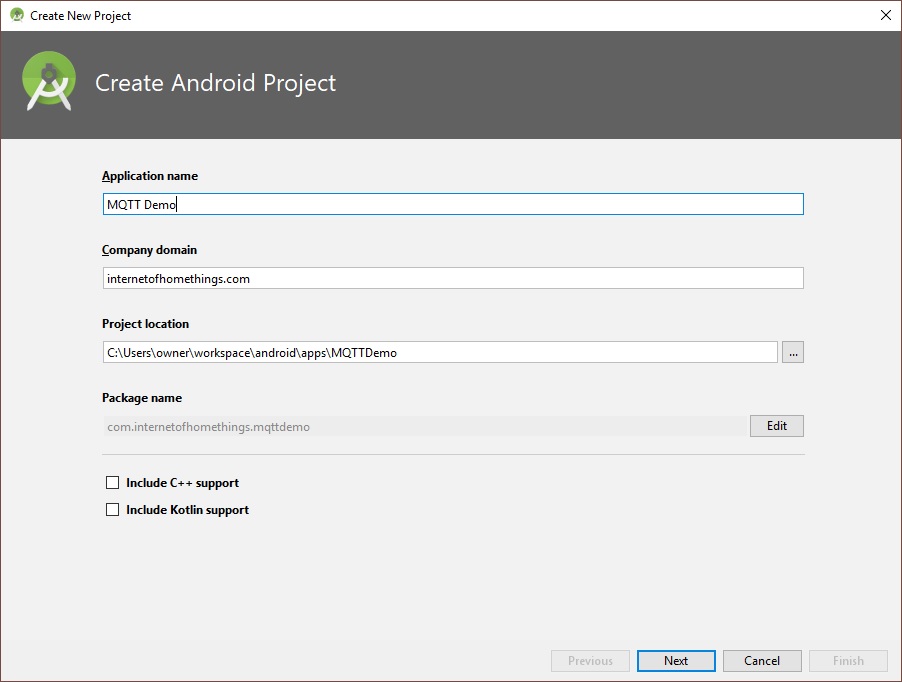
Enter a name for the project and click “Next”. The project location can be anywhere on your hard drive, ending with the folder name matching the project name:

These were the default settings used on the next screen:

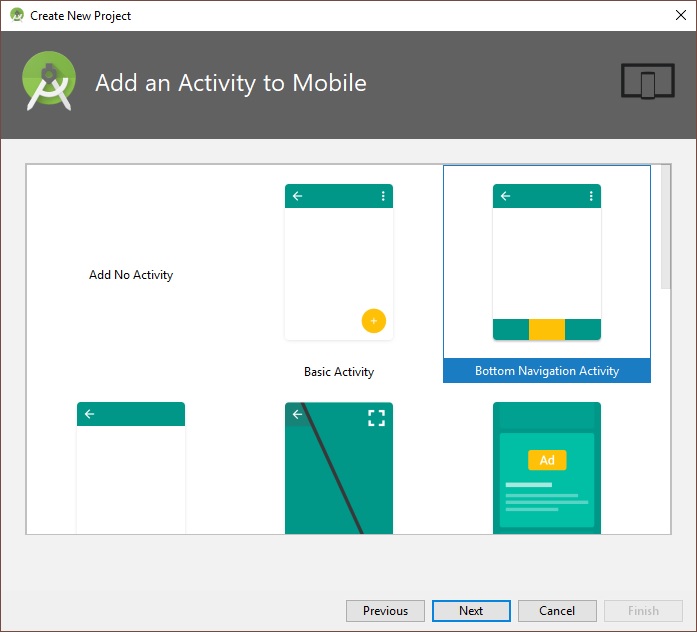
Next, Select “Bottom Navigation Activity”.

Use the default activity name:

Click “Finish” to complete the App framework creation.

The demo App will build.

Before we add the code for MQTT, it would be a good idea to build the apk and install the app on your android device to make sure the framework is functional.

Select Build-> Build APK(s) from the menu.


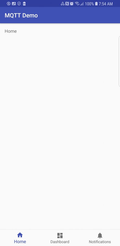
Click on “locate” to open the file manager with the location of the apk. You can transfer this file to your android device to test the app framework. The app should start to the following screen:

Now lets add the MQTT Demo code.

For this exercise, close Android Studio and simply replace the contents of the project folders with the files I have uploaded to Github here. Then we will walk through the code.

Copy <github/MQTTDemo> folder to <your project base directory>/MQTTDemo

The project files is partitioned into 3 main folders:

  1. <your project base directory>/MQTTDemo/app/build
  2. <your project base directory>/MQTTDemo/app/libs
  3. <your project base directory>/MQTTDemo/app/src

The build folder contains the output files from the build, libs contains the paho MQTT libraries, and src has the source code for the project. You can download the paho library files from here.

Now let’s open Android Studio to this project and review the source code:

The MQTT libraries as dependencies of your Android project

Open the build.gradle file. Here you will see the paho libraries added to file dependencies section:
dependencies {
    …    
    compile files(‘libs/org.eclipse.paho.android.service-1.1.1.jar’)
    compile files(‘libs/org.eclipse.paho.client.mqttv3-1.1.1.jar’)
}

Permissions and Service additions to the AndroidManifest.xml file

Open the app/AndroidManifest.xml file. Note the following permissions required by the app added to the manifest:
<usespermission android:name=“android.permission.INTERNET” />
<usespermission android:name=“android.permission.WAKE_LOCK” />
<usespermission android:name=“android.permission.ACCESS_NETWORK_STATE” />
<usespermission android:name=“android.permission.READ_PHONE_STATE” />
The Paho Android Service must also be added within the manifest <application> tag.

Customizing the App GUI (activity_main.xml file):

From Android Studio, the app opening GUI is layout is defined in the file app/res/layout/activity_main.xml

A preview of the GUI can be seen by selecting the “Design” tab while the xml code needed to generate the GUI can be edited from the “Text” tab.

While not necessary, inn order to make it easy to follow, the GUI components are listed in the xml file in the top-to-bottom order that they appear on the screen.

  • LinearLayout…requestFocus

Note that this object has a defined width and height of 0px, making it invisible. This object is used to set initial focus when the App is opened. Without this object, the app sets focus on the first editable field and the edit alphabet pop-up appears, somethings that is clearly undesirable on start-up.

  • LinearLayout…ScrollView…TextView

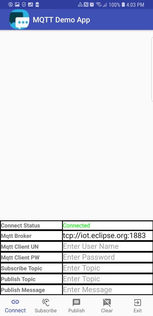
This object is the large white space in the layout above. It displays MQTT messages as they are received.

  • TableLayout

This object is the tabular information on the bottom half of the screen. This table is used to input MQTT connect parameters and to display the connect status.

  • BottomNavigationView

This object is the icons and text along the bottom of the screen. Upon tapping, these items trigger action by the app.

Bottom Navigation Menu (app/res/menu/navigation.xml file)

This file defines the five navigation items displayed along the bottom row of the screen. Three fields are needed for each item.

  1. id – identifies the item for access in the java code
  2. drawable = defines the item icon
  3. title – defines the text to be displayed under the item icon

The icons can be selected from the Android Studio library or a custom icon can be used. To add an icon to the project, right click on the app->res->drawable folder selecting New->Drawable resource file:

The java code (app/java/<project package name>/MainActivity.java)

The startup and callback code is contained in the MainActivity.java file. A separate file is needed for each app scree. Since this demo app only uses 1 screen, only 1 file is needed.

The App code (class Methods) are contained within the MainActivity class.

This apps simple method simple structure:

  1. onCreate – Executed upon App start-up
  2. <strong>RunScheduledTasks</strong> - Runs scheduled tasks once every second
  3. <strong>OnNavigationItemSelectedListener</strong> - Callback executed when a bottom navigation item is tapped.
  4. <strong>mqttCallback</strong> - Callback executed whenever a subscribed MQTT message is received

How it Works

When the app is started, GUI is rendered and onCreate is executed. Here is the sequence performed in onCreate:

  1. GUI layout is associated with the Apps opening activity
  2. A custom icon is added to the app’s title bar (you can change this, of course)
  3. A vertical scroller is added to the message window
  4. A client connection to the MQTT broker defined by the GUI table is made
  5. The bottom Navigation menu callback is registered.
  6. The text under each Navigation icon is made visible
  7. The callback for MQTT messages is registered
  8. The 1 second scheduled tasks callback is registered

After startup, the 3 app callback are active, waiting for a trigger to initiate execution

1. Scheduled tasks (runs once per second)

This App only requires one scheduled task. The app checks to see if the MQTT client is still connected to the broker. If connected, the display says “Connected” in green text. If the connection is lost, it displays “Disconnected” in red text.

2. Navigation Callback

The callback determines which item was tapped and then performs the applicable action:

Button 1: Connect – If connected to the broker, the connection is closed and then reconnected using the parameters currently displayed in the table. You can change the broker url prior to tapping this button to connect to a different broker, The table also has field for username/password if the broker supports and requires those fields. Using the paho library, two connection types are supported: tcp and ssl. An example of the broker url format for these connections:

tcp://&lt;broker domain&gt;:1883
ssl://&lt;broker domain&gt;:8883

Button 2: Subscribe – If connected to the broker, a subscription to the topic entered in the table is made. But if not connected, a message is displayed indicating a subscription cannot be added unless connected to the broker.

Button 3: Publish – If connected to the broker, the message entered is published to the topic entered in the table. But if not connected, a message is displayed indicating a message cannot be published unless connected to the broker.

Button 4: Clear – Erases the content of the message window.

Button 5: Exit – Exits the App.

3. Subscribed Topic Callback

The code executed when a subscribed message is receive is structured as if/then conditional statements. Once condition is executed for each unique topic executed. This provides a mechanism to execute topic specific code.

But in this demo App, the specified unique topics are not used. In that condition, the default “else” case is executed, which simply echos the published message in the message window.

In Closing

With the App framework presented, a full-featured app can be developed to interface with an MQTT broker to monitor and control your IoT devices. It can also be used as a client to test out MQTT clients connected to a common broker. Once again, the project can be downloaded from Github here.

Hope you find this project useful.

Loading

Share This:
FacebooktwitterredditpinterestlinkedintumblrFacebooktwitterredditpinterestlinkedintumblr

ESP8266 as a CoAP Client

coap1

Several examples can be found to configure the ESP8266 as a CoAP server. Last year I too had developed one. Here is my working example.

But what about using the device as a CoAP client? Using the ESP8266 to send requests to a CoAP server? With a two-ESP8266 module setup, this would provide the capability to set up a CoAP client/server architecture.

While I was unable to find a working example, much to my surprise, it was not that difficult to develop a client from my working server. Here is how it was done…

Turning the tables

After reviewing my ESP8266 CoAP server code, the seeds for a client were obvious. The server listens for CoAP request, acts on it, and sends a reply. To make a client, all that is necessary is to reverse the order.

First, use the server’s reply code to send a request to a server. Then simply listen for a reply from the CoAP server using the “listen” code.

Communication Structure 

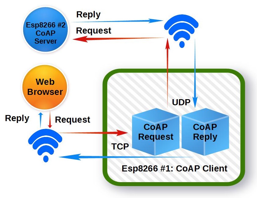
This project uses a standard http server to initiate requests to a CoAP server. With this structure, a standard web browser can be used to test the CoAP client functionality.


coap_client


Separate Requests and Replies 

Using http request to initiate a CoAP client request presents a slight complication. That is, I found that checking for a CoAP reply (UDP) from a request while the http (TCP) connection was open caused the ESP8266 to crash. The problem was that the TCP connection callback function blocks the CoAP UDP reply packet. It was stuck waiting until the ESP8266 watchdog timed out, and then… Crash!

One solution is to use an Asynchronous TCP library such as the one found here. But that is beyond the scope of this simple ESP8266 CoAP client project. However, I do intend to explore that option in a future post on this subject.

But for now, it was easier to resolve this problem by breaking down an http GET initiated CoAP communication  exchange into two parts. The first http GET sends a CoAP request to the target CoAP server. After the TCP connection is closed. the CoAP UDP reply is received and stored. A second http GET is then needed to retrieve the CoAP reply.

 Sending a CoAP Request 

A CoAP request is comprised of a UDP packet per RFC7252. This example uses a simple CoAP server installed on a second ESP8266 that supports just 3 actions.

  1. Turn Led On/Off
  2. Blink Led
  3. Get Sensor Values

The CoAP UDP request packets are pre-defined in unique byte arrays:


  1. uint8_t packetbuf_LED_ON[]     = {0x40, 0x03, 0x00, 0x00, 0xB5, 0x6C, 0x69, 0x67, 0x68, 0x74, 0xFF, 0x31};
  2. uint8_t packetbuf_LED_OFF[]    = {0x40, 0x03, 0x00, 0x00, 0xB5, 0x6C, 0x69, 0x67, 0x68, 0x74, 0xFF, 0x30};
  3. uint8_t packetbuf_LED_BLINK[]  = {0x40, 0x03, 0x00, 0x00, 0xBB, 0x6C, 0x69, 0x67, 0x68, 0x74, 0x5F, 0x62, 
  4. 0x6C, 0x69, 0x6E, 0x6B, 0xFF, 0x35};
  5. uint8_t packetbuf_GETSENSORS[] = {0x40, 0x03, 0x00, 0x00, 0xB7, 0x72, 0x65, 0x71, 0x75, 0x65, 0x73, 0x74, 
  6. 0xFF, 0x2F, 0x3F, 0x72, 0x65, 0x71, 0x75, 0x65, 0x73, 0x74, 0x3D, 0x47, 
  7. 0x65, 0x74, 0x53, 0x65, 0x6E, 0x73, 0x6F, 0x72, 0x73};

The first byte (0x40) identifies the CoAP version as 1.0. The ‘0’ in the lower 4 bits indicate no tokens will follow the message header. The second byte (0x03) identifies the CoAP code as 0.03, indicating the PUT method used in the UDP request packet. Bytes 3 and 4 contain the messageID. This value starts at 0 upon ESP8266 startup and is incremented every time a message is sent.

The lower 4 bits identify the packet option length and is followed by the option value. Then, the byte following the option is the payload deliminator, and is set to oxFF.

Size (bytes) Value (Hex) Value(char) Parameter
LED ON 5 6C 69 67 68 74 light 1
LED OFF 5 6C 69 67 68 74 light 0
LED BLINK 11 6C 69 67 68 74 5F 62 6C 69 6E 6B light_blink 0-9
GET SENSORS 72 65 71 75 65 73 74 request /?request=GetSensors

The packet payload, which follows the 0xFF deliminator, contains the request message. As shown in the table above, the parameter is set to 1 to turn the CoAP server ESP8266 circuit LED on and 0 to turn the LED off.

And just as with other web server request, the CoAP requests are sent (udp_send) after an http GET is received.


  1.                 // Send CoAP Request to ESP8266 (192.168.0.141)
  2.                 else if(os_strcmp(pURL_Param-&gt;pParVal[0], "CoAPLedOn")==0) {
  3.                     coaplen = sizeof(packetbuf_LED_ON);
  4.                     incrMessageID(packetbuf_LED_ON);            //Increment Mesaage ID 
  5.                     udp_send(packetbuf_LED_ON, coaplen);
  6.                     payld = "http GET 'CoAPGetReply' required to get CoAP reply"; 
  7.                 }
  8.                 // Send CoAP Request to ESP8266 (192.168.0.141)
  9.                 else if(os_strcmp(pURL_Param-&gt;pParVal[0], "CoAPLedOff")==0) {
  10.                     coaplen = sizeof(packetbuf_LED_OFF);
  11.                     incrMessageID(packetbuf_LED_OFF);          //Increment Mesaage ID 
  12.                     udp_send(packetbuf_LED_OFF, coaplen);
  13.                     payld = "http GET 'CoAPGetReply' required to get CoAP reply"; 
  14.                 }
  15.                 // Send CoAP Request to ESP8266 (192.168.0.141)
  16.                 else if( (os_strcmp(pURL_Param-&gt;pParVal[0], "CoAPLedBlink")==0)&amp;&amp;(os_strcmp(pURL_Param-&gt;pParam[1], "cnt")==0) ) {
  17.                     coaplen = sizeof(packetbuf_LED_BLINK);
  18.                     //Insert Blink Count (1-9)
  19.                     *pURL_Param-&gt;pParVal[1] = (*pURL_Param-&gt;pParVal[1] &lt; 0x31) ? 0x31 : *pURL_Param-&gt;pParVal[1];
  20.                     *pURL_Param-&gt;pParVal[1] = (*pURL_Param-&gt;pParVal[1] &gt; 0x39) ? 0x39 : *pURL_Param-&gt;pParVal[1];
  21.                     packetbuf_LED_BLINK[coaplen-1] = *pURL_Param-&gt;pParVal[1];
  22.                     incrMessageID(packetbuf_LED_BLINK);       //Increment Mesaage ID 
  23.                     udp_send(packetbuf_LED_BLINK, coaplen);   //Send Packet
  24.                     payld = "http GET 'CoAPGetReply' required to get CoAP reply"; 
  25.                }
  26.                 // Send CoAP Request to ESP8266 (192.168.0.141)
  27.                 else if(os_strcmp(pURL_Param-&gt;pParVal[0], "CoAPGetSensors")==0) {
  28.                     coaplen = sizeof(packetbuf_GETSENSORS);
  29.                     incrMessageID(packetbuf_GETSENSORS);     //Increment Mesaage ID 
  30.                     udp_send(packetbuf_GETSENSORS, coaplen);
  31. payld = "http GET 'CoAPGetReply' required to get CoAP reply";
  32.                 }
  33.                 // Send CoAP Request to ESP8266 (192.168.0.141)
  34.                 else if(os_strcmp(pURL_Param-&gt;pParVal[0], "CoAPGetReply")==0) {
  35.                     payld = String(coap_reply_c);
  36.                 }

Receiving the CoAP Reply 

Note in the above code that the CoAP reply is set (payld) after the UDP packet it sent to the CoAP server. But the reply simply states that you must send a ‘CoAPGetReply’ request in order to get the CoAP reply. As noted previously, that is due to the blocking nature of the TCP callback.

The actual reply is stored in the global character string ‘coap_reply_c’.To get the reply, simply send the second GET request:

<ESP_IP>:<ESP_PORT>/?request=CoAPGetReply

Example Transactions

So here is the browser based requests you can use the test this CoAP server. This example assumes the ESP IP is 192.168.0.141 and the TCP port is set to 9706.

URL (192.168.0.141:9706) Suffix http Reply
Set CoAP Server LED Off /?request=CoAPLedOff http GET 'CoAPGetReply' required to get CoAP reply
Set CoAP Server LED Off /?request=CoAPGetReply 0
Set CoAP Server LED On /?request=CoAPLedOn http GET 'CoAPGetReply' required to get CoAP reply
Set CoAP Server LED On /?request=CoAPGetReply 1
Set CoAP Server LED Blinking 3 times /?request=CoAPLedBlink&cnt=3 http GET 'CoAPGetReply' required to get CoAP reply
Get CoAP Server Sensor Values /?request=CoAPGetSensors http GET 'CoAPGetReply' required to get CoAP reply
Get CoAP Server Sensor Values /?request=CoAPGetReply { "Ain0":"142.00", "Ain1":"143.00", "Ain2":"143.00", "Ain3":"145.00", "Ain4":"144.00", "Ain5":"145.00", "Ain6":"144.00", "Ain7":"140.00", "SYS_Heap":"32896", "SYS_Time":"37" }

This project’s GitHub Repository 

In Closing 

There you have it. A simple ESP8266 CoAP client structure to use in your custom application. But this is just a starting framework. There are obvious enhancements that can be made to this working example. Here are some of the things I would do next…

  1. Add web configurable options – Example
  2. Revise to support Async TCP
  3. Implementation of additional RFC7252 options

Hope you find this information useful…

Loading

Share This:
FacebooktwitterredditpinterestlinkedintumblrFacebooktwitterredditpinterestlinkedintumblr

Getting Started with the ESP8266-12

I was really excited when first discovering the ESP8266. Imagine…a tiny footprint device capable of connecting to the internet with a WIFI connection. With the capability to control ‘things’ and monitor sensors. A genuine SoC (System on a Chip). And best of all…for a price under 5 USD.

I was determined to make this as low cost as possible. So I found an inexpensive Asian supplier and ordered a lot of 5 of them for $2.68 each. And FREE shipping.

But I knew the delivery would be slow with these terms so I researched what else was needed. A USB to serial converter was the only other thing essential to getting started. This would be used both for programming the ESP8266 and providing it with the required 3.3V power source. Another search netted a supplier of these at $0.64 each (minimum order of 10).

Hmmm…if this works, throw in a couple of sensors and stuff and we what we have is still a very low-cost solution to internet-enable something—perhaps EVERYTHING!

It did take a while for those ESP8266 devices to arrive…46 days from the order date. But hey, with all my other “irons in the fire”, this was not even an inconvenience.

So when the hardware arrived, I started to search for a simple way to get started. What I found was that there are many variants of the ESP8266, and they do not all behave exactly the same. I had ordered the ESP8266-12 models. These were 16-pin devices and all the information I found was for the earlier designs, the 8-pin variety. And yes, there is an important set-up for the ESP8266-12 that was not mentioned for the earlier units.

The purpose of this document is to provide a ‘getting started quickly’ guide for the ESP8266-12. What’s great is that almost all of the steps also apply to the earlier versions.

The ESP8266 is an open-source device with bits and pieces of the puzzle scattered about. Piecing it all together can be somewhat challenging. I hope the information presented here makes it possible for someone to get started quicker and easier than I did, without needed to jump elsewhere for missing pieces.

Getting started with the ESP8266 breaks down into five steps:

  1. Connecting the hardware

  2. Install the USB to serial device driver

  3. Verify the unit is functional

  4. Flashing NodeMcu

  5. Installing an application

Step 1: Connecting the hardware

This is a list of all the components I used to get started:

  • ESP8266 module
  • USB to Serial converter
  • 3.3V 1A Power Supply
  • Capacitor (4.7uf)
  • LED
  • Resistors (10 kohm (3), 330 ohm, 100 ohm)
  • Zener Diode (3.3V)
  • Breadboard
  • Jumper wires

ESP8266 in ESD bag


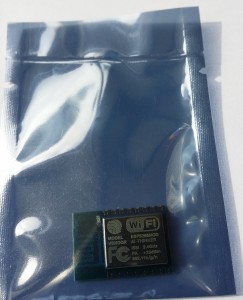
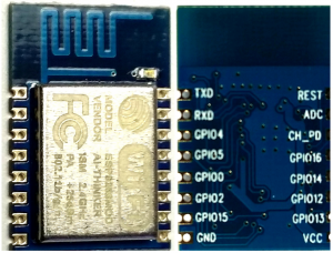
The ESP8266-12 units were delivered in sealed ESD bags. No headers were installed on the printed wiring board. But a bigger issue was that the centers between each pin (8 on each side) are 2mm. That is tighter than the 2.54 mm of a standard breadboard.

ESP8266-12 Top and Bottom Views

ESP8266-12 Top and Bottom Views


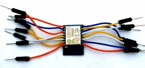
First challenge was to make the module mountable on a breadboard. Anxious to get started, I took the quick and dirty route and simply cut 8 breadboard jumpers in half, enough for 16 signals. The cut end was stripped and soldered to the ESP8266-12, one wire on each of the 16 holes. This got me started quickly without needing anything extra, like a separate perforated board to break-out the signals. Not pretty, but it’s working just fine for initial prototyping.

ESP8266-jumpers

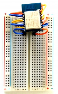
The “jumper-ed” module mated easily to a breadboard.

I would have used shorter jumpers if I had make this setup again. With tighter connections, the jumper pins would have connected to the breadboard somewhat cleaner; almost straight down from the module. But then, this is just a quick-start setup and has proven to be quite reliable.

ESP8266-OnBreadboard

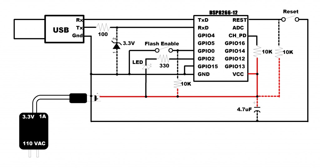
As an initial test, a simple flashing LED will be coded. As shown below, the hardware needed for this is minimal. Note that GPIO15 must be grounded. That fact was not stated in much the information available on-line regarding this module. The unit will simply not work without this connection. I hope this saves someone from the initial grief I went through prior to properly configuring GPIO15.

schematicNEW

A few notes regarding the circuit:

  • Components connected with ‘dashed’ line are optional but recommended for reliable operation.

  • Connecting GPIO0 to ground should only be made when flashing the ESP8266. It is shown with a switch in the path, but simply adding this connection as a breadboard jumper when flashing is adequate.

  • During development and testing, there will be times when you will ant to reset the module. This can be done by momentarily connection a jumper from REST to ground.

  • The 100 ohm resistor and 3.3V zener diode from the USB transmit signal to the ESP8266 receive protects the ESP8266 from potential damage from exposure to 5V. The module is not specified to accept any inputs greater than 3.3V.

  • It is a good practice to have a capacitor across the power rails near the active components. The 4.7 uF capacitor I used is larger than what is needed for this simple circuit. I suggest using one greater than 0.1 uF.

  • A separate 3.3V power source is needed. Do not use the USB 3.3V output.

To be honest, my initial set-up did not even include the external power supply. I was using the 3.3V provided by the USB to serial bridge (top contact of red device above). But the performance was intermittent. Sometimes it would fail during a flash, and the unit would often freeze it’s activity after a short time running. These problems were eliminated after using an external supply to power the ESP8266.

The problem is that the USB bridge’s 3.3V output provides insufficient power. The current tops out at 100 ma while the ESP8266 can require more than 200 ma. I recommend that you save yourself some headaches; USE A SEPARATE 3.3V POWER SUPPLY.

Slow boat from China

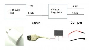
Another power supply option: Almost everyone has a few 5V USB wall plus for various uses. And who doesn’t also have one or more USB cables that no longer charge properly? These cables, along with a cheap 3.3V voltage regulator offer an inexpensive way to satisfy the ESP8266 power requirements. I have found a supplier selling regulators, model LM1117, for 0.04 USD each, but you have to order a minimum of 100, a lifetime supply for 4 USD…and this includes free shipping). Only catch is that it will take about 45 days to receive the goods on that slow boat from China).

5V_3.3V

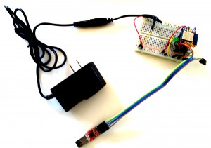
Here is what my test setup looked like after all the jumpers were in place:

ESP8266-TestSetup

Step 2: Install the USB to serial device driver

If you have already have a working serial interface, you can skip this section and move on to step 3.

There are many USB to serial devices available that will work well to program the ESP8266. If you do not have one already, you simply need a serial port with 3 signals:

  • Transmit

  • Receive

  • Ground

The one I selected provided 3.3V output. At the time, I thought this was essential, thinking that it would be needed to drive the ESP8266. But now, using an external supply for the 3.3V source, this voltage out of the USB to serial module is not necessary and is not used.

Just follow the instructions for your serial port to install the drivers. Installation for my device, which is based on a CP210x chip, is provided in a separate post.

Step 3: Verify the unit is functional

We now have the hardware setup established. Let’s make this thing work. Here is where things start to get interesting.

First, connect the USB to serial device to your computer and plug in the power supply. If the ESP8266-12 is functional, you should see the blue led flash twice when the power is applied. Great, this is the first confirmation that the unit is alive.

What is needed now is a method to verify the unit is functional, the ability to develop code and to flash the unit with code. Here we go…

First, open up your favorite terminal program such as putty or tera-term.

Start-up by applying power to the unit, or connect and release a jumper from REST to ground with a powered up unit.

Expect the blue led to flash twice on start-up.

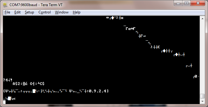
Note that start-up output at the terminal windows is garbage at both 9600 and 115200 baud. I tried this at all baud rates from 110 to 921600…none of these rates resulted in a recognizable output.

initialserialoutput

This suggests that the unit is not shipped with firmware. To get started then, you will need to get the AT command set firmware and flasher. There are many sites that have it. I got my copy here.

Knowing that things change over time, it is suggested that you do a search for “ESP8266 flasher” if it is no longer at the site mentioned.

Flashing the AT command firmware

Now let’s flash some firmware:

  • Ground GPIO0 and start-up or reset device.

    • You should see the blue LED flash once.

  • Run the executable “esp8266_flasher.exe” that was just downloaded.

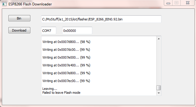
  • Click the “Bin” button to select the downloaded firmware (ESP_8266_BIN0.22.bin).

  • Enter the COMx number assigned to your serial port (mine was 7).

  • Click “download.

ESP8266Flasher

When the download finishes, you will see “Failed to leave Flash mode”

Ignore this and close the downloader program.

Remove the GPIO0 to ground connection.

Reset the ESP8266: You will see two blue flashes again (the second flash is dimmer than the first).

The firmware is running at 115200 now and should respond to AT commands.

The most basic command to verify the firmware:

Enter “AT<enter>”

ESP8266 response: OK

The complete AT command set can be found here.

If you plan to use the ESP8266 as a slave to an Arduino or other MCU, you are ready to go.

But if you are planning to use the ESP8266 as a stand-alone prototyping platform, read on…

Step 4: Flashing NodeMcu

NodeMcu is open-source firmware for the ESP8266 which makes it easy to prototype “things”. It is similar to the Arduino development environment.

More information is available here.

Let’s set up the ESP8266 for NodeMcu.

First, pull the Flasher and firmware from GitHub:

Click on the “Download ZIP” file to get the entire package.

I used the 64-bit version for my windows 7 PC. It was in the repository at:

nodemcu-flasher-master\Win64\Release\ESP8266Flasher.exe

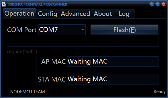
Before starting this program, make sure the GPIO0 is connected to ground. Then start the flasher program which should start up with:

ESP8266 Flasher NodeMcu

The COM Port should be the same one you have been using to communicate with the ESP8266.

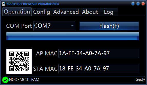
Click on the “Flash(F)” button to flash NodeMcu on your device. This will take a few minutes. You will see the progress bar fill and the ESP8266 blue LED blink during the flashing. A green Check will be displayed when the flash is completed.

After Flashing ESP8266 with NodeMcu

Once the flash is complete, you can remove the GPIO0 to ground jumper. It will no longer be needed. All that you will need now to develop your own applications is an integrated development environment (IDE).

ESPlorer appears to be the most widely used ESP8266 IDE. Get it now here.

Simply run the batch file “ESPlorer.bat” to start the IDE. A command window will be launched along with the IDE GUI. DO NOT close the command window!

ESPlorer IDE

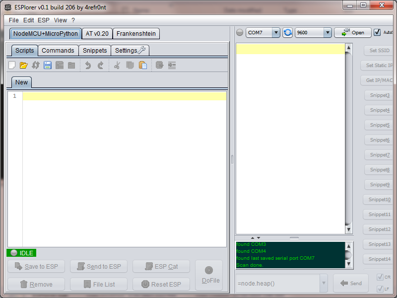
The ESP8266 starts up now with it’s serial port set to 9600 baud. In order to start the communication link, you will need to click on the “Open” button (COM port set to the number corresponding to the ESP8266 to PC serial bus).

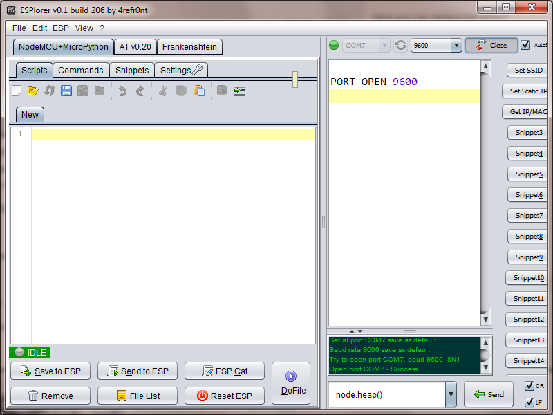
If the port opens successfully, the IDE window will look like this:

ESPlorer2

Now click on the “ResetESP” button. The ESP8266 should respond with the firmware version:

node.restart()

> #ü!##¤„ÿ1ä)Mô1ä)}†1¤ñ¡Hø

NodeMCU 0.9.5 build 20150311 powered by Lua 5.1.4

>

Congratulations! Your ESP8266 development environment is now set up.

Step 5: Installing an application

It is time to write and flash our first program.

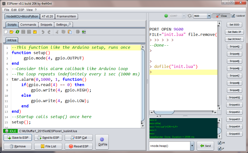
Lets try writing a simple program to blink an LED on and off. It is structure here to appear similar to the familiar Arduino structure. The code is entered in the window with the “Scripts” tab selected:

ESPlorer3

Notice the file is assigned the name “init.lua”. This is the default file that is run on the ESP8266 at start-up. This program simply toggles the LED state every 1 second. The GPIO2 is assigned an index 4, which is why this value is used in our script to control the connected LED.  Look here for the remaining GPIO to index mapping. Simply click on the “Save to ESP” button to flash the code to the ESP8266. The LED should then change state every 1 second.

Also note the ‘dofile(“init.lua”)’ in the right window. The IDE commands the ESP8266 to start this script after flashing with this command.

NOTE: While it may change in the future, currently, the IDE does not provide a means to create new files to your PC. The file “init.lua” must be created with an external text editor before it can be opened in the IDE.

This is just the beginning… A starting point so you can begin exploring what is possible with this remarkable device. I have already made a simple server to control an LED from a web-page and return a JSON string. I’ll leave that as an exercise for you and perhaps provide the details in another post.

The complete API and GPIO index mapping is maintained here.

And there are examples of different code snippets, including configuring the ESP8266 WIFI for internet here.

I’ll be back with more as I get more experience with this device.

My next step is to port the code I have currently deployed to a Spark Core (running continuously for almost a year now) to the ESP8266-12 platform to compare performance.

What will you do next?

Loading

Share This:
FacebooktwitterredditpinterestlinkedintumblrFacebooktwitterredditpinterestlinkedintumblr

ESP8266 Power and Serial Interface

So now you’ve gotten your hands on an ultra low-cost ESP8266 module.

Your ready to get started…

But what else do you need?

The only other hardware you need now to make this thing functional is an interface for development. This interface must support firmware flashing and testing. It must also provide a power source. Fortunately, there are several low-cost options available to satisfy these basic needs.

What you need is a USB to serial converter. Of the models available…and there are several unique ones available, it is essential that you choose one that provides a 3.3V output required by the ESP8266. This output is not present on all converters so you must make sure you select one that does. The standard 5Vdc USB output is too high for the chip, and will most likely destroy it. And nobody wants another brick in the stash of gadgets!

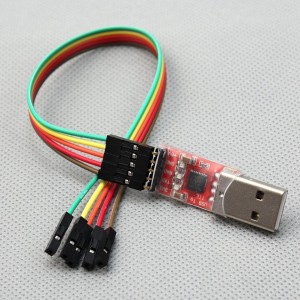
From a brief search on Amazon, I found a device that met the requirements. My device uses a CP210x chip-set. While I could have purchased a cheaper unit from an Asian supplier, this was still a decent value at less than 4 USD and with fast-free shipping, I got the device in days instead of months.

Making prototyping a snap, a 5 pin ribbon cable is included with female contacts that can be attached directly to male breadboard jumpers.

ESP8266 Power and Serial Interface

From this USB plug-in module, 5 signals are provided:

      • 5 Vdc
      • 3.3 Vdc
      • Ground
      • Serial Tx
      • Serial Rx

But remember, the 5Vdc output must not be used when interfacing with the ESP8266.

Since I am using a Windows 7 OS PC for development, a compatible driver was needed to make this device functional. For this device, the driver can be found at:
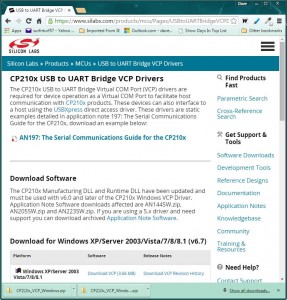
https://www.silabs.com/products/mcu/Pages/USBtoUARTBridgeVCPDrivers.aspx
There are drivers available there for Windows, Windows CE, Linux, and Macintosh.
Driver installation is straightforward. Simply download the files and follow the instructions from this website.


usb_driver


I used the Windows Device Manager to install the driver. There are several ways to pull up the Device Manager on a Windows PC. One simple method is to type “Device Manager” in the Start pop-up in the box with the placeholder “Search programs and file”:


Open Device Manager


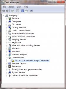
With the USB device attached to the PC (with no driver installed), right-click on the device and select “Update Driver Software…”


DeviceManagerBefore


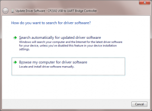
Then, select “Browse my computer for driver Locate and install driver software manually.”


UploadDriverSoftware1


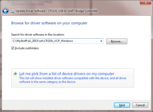
Select the folder that the driver downloaded to on your computer:


UploadDriverSoftware2


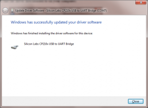
Clicking “next” installs the driver…and that should do it:


Finished


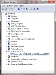
When you click “close”, the driver should be installed and the device manager updated with the correct driver information, including the COMx assignment.

DeviceManagerAfter


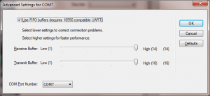
If you want to customize the COMx port number assignment, right-click on the newly installed USB to UART bridge driver, select “Properties, the “Port Settings” tab and “Advanced…”


ComPortAssignment


Note that while the USB to serial device’s 3.3V output can be used to power the ESP8266 when programming the device, it is inadequate as a stand-alone power source. The maximum output is specified to be 100ma while the ESP8266, when transmitting, could require up to 215 ma. Even though the ESP8266 can be programmed for several lower power transmit modes, none falls below the 100ma maximum that the USB to serial device can deliver.

          • Transmit 802.11b, POUT=+19.5dBm 215 mA
          • Transmit 802.11b, POUT=+18.5dBm 197 mA
          • Transmit 802.11g, POUT=+16.0dBm 145 mA
          • Transmit 802.11n, POUT=+14.0dBm 135 mA

Thus, a separate 3.3V source is needed to power the ESP8266 for a fielded application What is important to keep in mind is that the ESP8266 needs a regulated 3.3V power source. I recommend using a single-chip regulator for this purpose.

One such device, which can be purchased fro about 1 USD on-line from Amazon or Adafruit, is the 3.3V 250MA LINEAR VOLTAGE REGULATOR (Part number L4931).

This unit will regulate any source (3.7 – 20 Vdc) down to a clean 3.3V, and providing up to 250 ma.

3.3V Voltage Regulator
With this simple circuit, you can use any commonly available USB source to power your ESP8266 based project. Just make sure the source is rated to supply the needed current. Power sources like a USB battery, car or wall adapter.

Until next time…

Loading

Share This:
FacebooktwitterredditpinterestlinkedintumblrFacebooktwitterredditpinterestlinkedintumblr

Press Ctrl+C to copy the following code.
"