Web Server

Your Own VPS for IoT and More

Having a Virtual Private Server (VPS) at your disposal opens up boundless IoT possibilities – all under your direct control – with no reliance on third-party cloud services. Like hosting your own MQTT broker, CoAP server, and scheduling periodic tasks to monitor and control your IoT devices or store/retrieve information using a database. Website hosting, including popular CMS sites such as WordPress, Joomla!, Drupal and more as well as file/picture sharing are also possible with your VPS.

Does this seem like a daunting task? Difficult to set-up? And expensive?

It doesn’t have to be.

Building on a past project, all  I did initially was port my USB Thumb Drive LAMP server to a VPS. And the basic framework, including the Linux distribution  you choose to use, are installed automatically for you. This greatly simplifies the setup…

Shared Host vs VPS

Before moving on with VPS, it should be noted that “Shared Host” are also available. They are tempting as the lowest cost available, they do not provide the capabilities or flexibility of VPS, and thus are not addressed in this post. Here is one decent article I have found that provides clear support for the superiority of VPS over a shared host. You are in control with a VPS, free from the restrictions placed on a shared host account.

Selecting a VPS Provider 

First thing you have to do is select a VPS provider. There are many to choose from. All options I have seen start with a basic package and scale up to fit your needs. For basic DIY IoT enthusiasts, the entry-level offering provides more capability that you should ever need. Here are a few of the VPS providers and their basic features:

Website Cost/month CPU Cores RAM Storage Transfer
LiNode linode.com $5.00 1 1G 20G SSD 1 TB
LiNode linode.com $10.00 1 2G 30G SSD 2 TB
iPage iPage.com $19,99 1 1G 40G 1 TB
HostGator HostGator.com $19,95 2 2G 120G 1.5 TB
FatCow fatcow.com $19,99 1 1G 40G 1 TB
JustHost justhost.com $19,99 2 2G 30G 1 TB
Bluehost bluehost.com $19,99 2 2G 30G SAN 1 TB

I found that the Linode option offered the best value. At 10 USD per month, this provider was the lowest cost of the ones I had looked at. And recently, they have added even a lower, 5 USD per month package. In fact, there were many others that offered teaser rates initially, only to cost much more than the rates listed above. Those providers were eliminated from my consideration.

LiNode uses Solid-State Disks (SSD) which yield lightning fast performance, even with the entry level package that uses a single CPU core. I have been had an active VPS account with LiNode for about a year now, with 100% uptime.

If you do choose to setup a VPS using LiNode, please consider using this link, which, full disclosure, would provide me with a referral credit to help fund my own VPS account and continue sharing information.

Operating System Options 

LiNode VPS provides step-by-step instructions for setting up your system. While I do not have any personal experience, I suspect other VPS providers offer similar directions to simplify the setup procedure. or those familiar with Linux, here are the distributions that LiNode offers for immediate deployment:

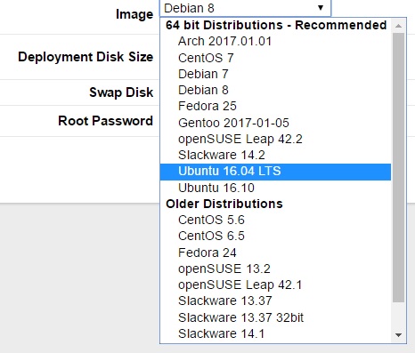
I chose to deploy Ubuntu 16.04 LTS, which is a widely used distribution. With that basic configuration, I have customized the setup for my own personal needs.

Exploiting Your VPS Platform 

Once your VPS is setup, it is ripe and ready for practical applications. The first thing many DIY enthusiasts will want to add is a private MQTT broker. As an avid ESP8266, the first 3 applications listed below can interface directly with the VPS. This and other uses for the VPS will be covered in follow-up posts…

  • VPS Application 1: MQTT Broker
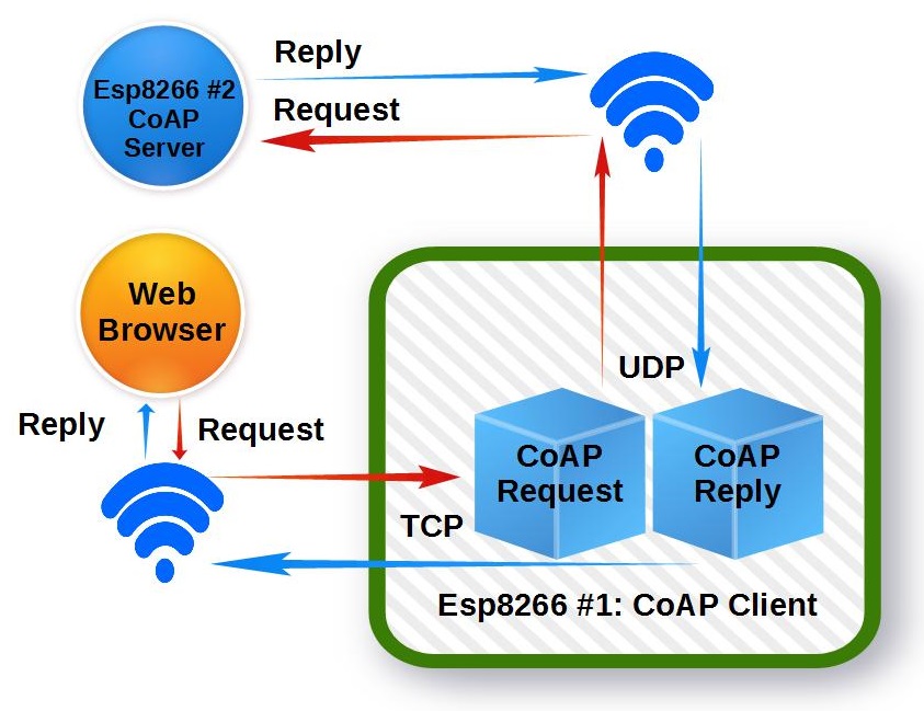
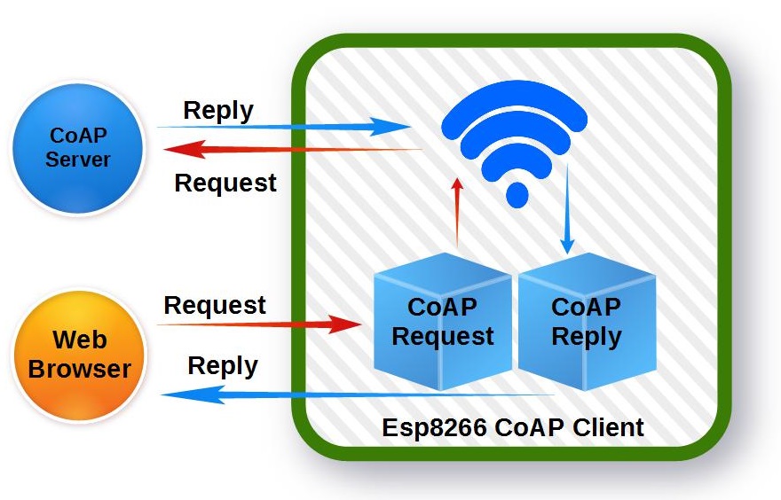
  • VPS Application 2: CoAP Server
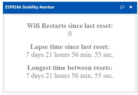
  • VPS Application 3: Scheduled IoT Monitor/Control Scripts
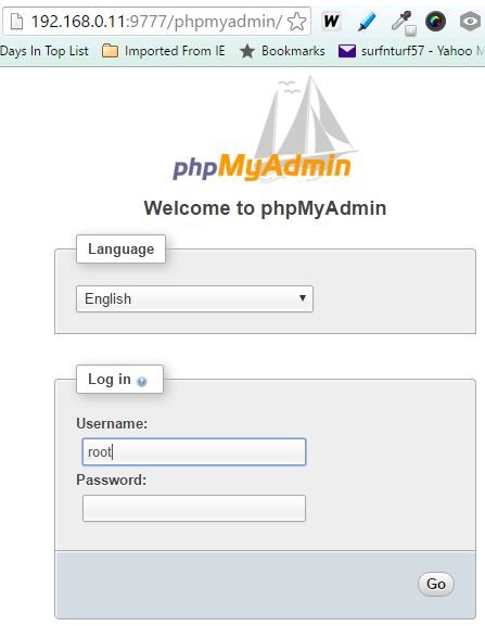
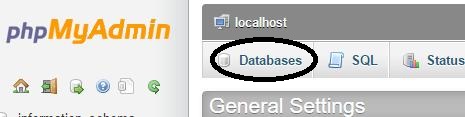
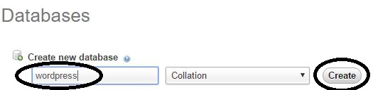
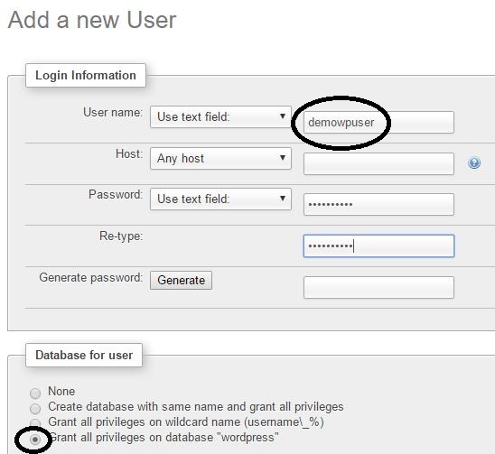
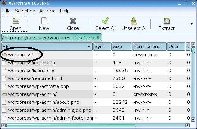
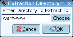
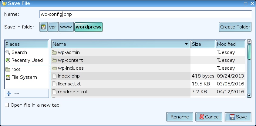
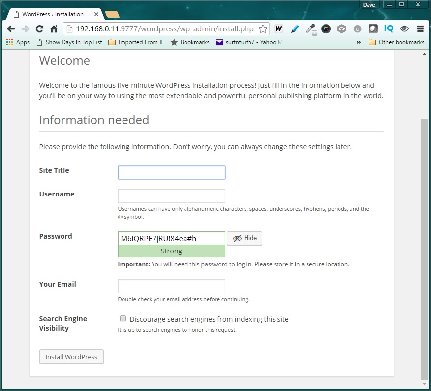
  • VPS Application 4: Hosting a Website
  • VPS Application 5: Private Email Server

And this is just the beginning.

Hope you find this information useful.

Loading

Share This:
FacebooktwitterredditpinterestlinkedintumblrFacebooktwitterredditpinterestlinkedintumblr

ESP8266 as a CoAP Client

coap1

Several examples can be found to configure the ESP8266 as a CoAP server. Last year I too had developed one. Here is my working example.

But what about using the device as a CoAP client? Using the ESP8266 to send requests to a CoAP server? With a two-ESP8266 module setup, this would provide the capability to set up a CoAP client/server architecture.

While I was unable to find a working example, much to my surprise, it was not that difficult to develop a client from my working server. Here is how it was done…

Turning the tables

After reviewing my ESP8266 CoAP server code, the seeds for a client were obvious. The server listens for CoAP request, acts on it, and sends a reply. To make a client, all that is necessary is to reverse the order.

First, use the server’s reply code to send a request to a server. Then simply listen for a reply from the CoAP server using the “listen” code.

Communication Structure 

This project uses a standard http server to initiate requests to a CoAP server. With this structure, a standard web browser can be used to test the CoAP client functionality.


coap_client


Separate Requests and Replies 

Using http request to initiate a CoAP client request presents a slight complication. That is, I found that checking for a CoAP reply (UDP) from a request while the http (TCP) connection was open caused the ESP8266 to crash. The problem was that the TCP connection callback function blocks the CoAP UDP reply packet. It was stuck waiting until the ESP8266 watchdog timed out, and then… Crash!

One solution is to use an Asynchronous TCP library such as the one found here. But that is beyond the scope of this simple ESP8266 CoAP client project. However, I do intend to explore that option in a future post on this subject.

But for now, it was easier to resolve this problem by breaking down an http GET initiated CoAP communication  exchange into two parts. The first http GET sends a CoAP request to the target CoAP server. After the TCP connection is closed. the CoAP UDP reply is received and stored. A second http GET is then needed to retrieve the CoAP reply.

 Sending a CoAP Request 

A CoAP request is comprised of a UDP packet per RFC7252. This example uses a simple CoAP server installed on a second ESP8266 that supports just 3 actions.

  1. Turn Led On/Off
  2. Blink Led
  3. Get Sensor Values

The CoAP UDP request packets are pre-defined in unique byte arrays:


  1. uint8_t packetbuf_LED_ON[]     = {0x40, 0x03, 0x00, 0x00, 0xB5, 0x6C, 0x69, 0x67, 0x68, 0x74, 0xFF, 0x31};
  2. uint8_t packetbuf_LED_OFF[]    = {0x40, 0x03, 0x00, 0x00, 0xB5, 0x6C, 0x69, 0x67, 0x68, 0x74, 0xFF, 0x30};
  3. uint8_t packetbuf_LED_BLINK[]  = {0x40, 0x03, 0x00, 0x00, 0xBB, 0x6C, 0x69, 0x67, 0x68, 0x74, 0x5F, 0x62, 
  4. 0x6C, 0x69, 0x6E, 0x6B, 0xFF, 0x35};
  5. uint8_t packetbuf_GETSENSORS[] = {0x40, 0x03, 0x00, 0x00, 0xB7, 0x72, 0x65, 0x71, 0x75, 0x65, 0x73, 0x74, 
  6. 0xFF, 0x2F, 0x3F, 0x72, 0x65, 0x71, 0x75, 0x65, 0x73, 0x74, 0x3D, 0x47, 
  7. 0x65, 0x74, 0x53, 0x65, 0x6E, 0x73, 0x6F, 0x72, 0x73};

The first byte (0x40) identifies the CoAP version as 1.0. The ‘0’ in the lower 4 bits indicate no tokens will follow the message header. The second byte (0x03) identifies the CoAP code as 0.03, indicating the PUT method used in the UDP request packet. Bytes 3 and 4 contain the messageID. This value starts at 0 upon ESP8266 startup and is incremented every time a message is sent.

The lower 4 bits identify the packet option length and is followed by the option value. Then, the byte following the option is the payload deliminator, and is set to oxFF.

Size (bytes) Value (Hex) Value(char) Parameter
LED ON 5 6C 69 67 68 74 light 1
LED OFF 5 6C 69 67 68 74 light 0
LED BLINK 11 6C 69 67 68 74 5F 62 6C 69 6E 6B light_blink 0-9
GET SENSORS 72 65 71 75 65 73 74 request /?request=GetSensors

The packet payload, which follows the 0xFF deliminator, contains the request message. As shown in the table above, the parameter is set to 1 to turn the CoAP server ESP8266 circuit LED on and 0 to turn the LED off.

And just as with other web server request, the CoAP requests are sent (udp_send) after an http GET is received.


  1.                 // Send CoAP Request to ESP8266 (192.168.0.141)
  2.                 else if(os_strcmp(pURL_Param->pParVal[0], "CoAPLedOn")==0) {
  3.                     coaplen = sizeof(packetbuf_LED_ON);
  4.                     incrMessageID(packetbuf_LED_ON);            //Increment Mesaage ID 
  5.                     udp_send(packetbuf_LED_ON, coaplen);
  6.                     payld = "http GET 'CoAPGetReply' required to get CoAP reply"; 
  7.                 }
  8.                 // Send CoAP Request to ESP8266 (192.168.0.141)
  9.                 else if(os_strcmp(pURL_Param->pParVal[0], "CoAPLedOff")==0) {
  10.                     coaplen = sizeof(packetbuf_LED_OFF);
  11.                     incrMessageID(packetbuf_LED_OFF);          //Increment Mesaage ID 
  12.                     udp_send(packetbuf_LED_OFF, coaplen);
  13.                     payld = "http GET 'CoAPGetReply' required to get CoAP reply"; 
  14.                 }
  15.                 // Send CoAP Request to ESP8266 (192.168.0.141)
  16.                 else if( (os_strcmp(pURL_Param->pParVal[0], "CoAPLedBlink")==0)&&(os_strcmp(pURL_Param->pParam[1], "cnt")==0) ) {
  17.                     coaplen = sizeof(packetbuf_LED_BLINK);
  18.                     //Insert Blink Count (1-9)
  19.                     *pURL_Param->pParVal[1] = (*pURL_Param->pParVal[1] < 0x31) ? 0x31 : *pURL_Param->pParVal[1];
  20.                     *pURL_Param->pParVal[1] = (*pURL_Param->pParVal[1] > 0x39) ? 0x39 : *pURL_Param->pParVal[1];
  21.                     packetbuf_LED_BLINK[coaplen-1] = *pURL_Param->pParVal[1];
  22.                     incrMessageID(packetbuf_LED_BLINK);       //Increment Mesaage ID 
  23.                     udp_send(packetbuf_LED_BLINK, coaplen);   //Send Packet
  24.                     payld = "http GET 'CoAPGetReply' required to get CoAP reply"; 
  25.                }
  26.                 // Send CoAP Request to ESP8266 (192.168.0.141)
  27.                 else if(os_strcmp(pURL_Param->pParVal[0], "CoAPGetSensors")==0) {
  28.                     coaplen = sizeof(packetbuf_GETSENSORS);
  29.                     incrMessageID(packetbuf_GETSENSORS);     //Increment Mesaage ID 
  30.                     udp_send(packetbuf_GETSENSORS, coaplen);
  31. payld = "http GET 'CoAPGetReply' required to get CoAP reply";
  32.                 }
  33.                 // Send CoAP Request to ESP8266 (192.168.0.141)
  34.                 else if(os_strcmp(pURL_Param->pParVal[0], "CoAPGetReply")==0) {
  35.                     payld = String(coap_reply_c);
  36.                 }

Receiving the CoAP Reply 

Note in the above code that the CoAP reply is set (payld) after the UDP packet it sent to the CoAP server. But the reply simply states that you must send a ‘CoAPGetReply’ request in order to get the CoAP reply. As noted previously, that is due to the blocking nature of the TCP callback.

The actual reply is stored in the global character string ‘coap_reply_c’.To get the reply, simply send the second GET request:

<ESP_IP>:<ESP_PORT>/?request=CoAPGetReply

Example Transactions

So here is the browser based requests you can use the test this CoAP server. This example assumes the ESP IP is 192.168.0.141 and the TCP port is set to 9706.

URL (192.168.0.141:9706) Suffix http Reply
Set CoAP Server LED Off /?request=CoAPLedOff http GET 'CoAPGetReply' required to get CoAP reply
Set CoAP Server LED Off /?request=CoAPGetReply 0
Set CoAP Server LED On /?request=CoAPLedOn http GET 'CoAPGetReply' required to get CoAP reply
Set CoAP Server LED On /?request=CoAPGetReply 1
Set CoAP Server LED Blinking 3 times /?request=CoAPLedBlink&cnt=3 http GET 'CoAPGetReply' required to get CoAP reply
Get CoAP Server Sensor Values /?request=CoAPGetSensors http GET 'CoAPGetReply' required to get CoAP reply
Get CoAP Server Sensor Values /?request=CoAPGetReply { "Ain0":"142.00", "Ain1":"143.00", "Ain2":"143.00", "Ain3":"145.00", "Ain4":"144.00", "Ain5":"145.00", "Ain6":"144.00", "Ain7":"140.00", "SYS_Heap":"32896", "SYS_Time":"37" }

This project’s GitHub Repository 

In Closing 

There you have it. A simple ESP8266 CoAP client structure to use in your custom application. But this is just a starting framework. There are obvious enhancements that can be made to this working example. Here are some of the things I would do next…

  1. Add web configurable options – Example
  2. Revise to support Async TCP
  3. Implementation of additional RFC7252 options

Hope you find this information useful…

Loading

Share This:
FacebooktwitterredditpinterestlinkedintumblrFacebooktwitterredditpinterestlinkedintumblr

Continuous ESP8266 Operation

esp8266

Many ESP8266 enthusiasts still struggle with unwanted resets and non-recoverable system crashes. That comes from my recent review of the most often expressed issues noted on-line. After investing significant time with this module, many have simply given up and moved on with other options.

That is too bad…

And while I have written several articles on the subject, I have to admit that my long-term ESP8266 reliability test also failed months ago. But the test had not been revisited. That is. not until now. The problem was that the original tests were using an older, less reliable sketch structure.

Now, with some much-needed improvements, my basic setup now provides a reliable and stable platform for IoT projects. That is the point of this writing. The following information should prove useful for anyone wanting to use the ESP8266 on a 24/7 basis with minimal or no down-time…

Here’s a reference to my past writings on this topic:

4 ways to eliminate ESP8266 Resets

A cleaner ESP8266-12 hardware setup

ESP8266 WIFI dropout-proof connectivity

Past Monitoring the Esp8266 Performance

My original reliability test used a ThingSpeak channel to monitor the ESP8266 performance. This same channel will now be reused to evaluate  the updated sketch structure. The longest run-time recorded during the original test was 28 days. Then, the ESP8266 crashed fatally and could not recover. Yet every 24 hour period  in the 28 day span recorded at least 10 ESP8266 resets. Fortunately, the sketch was structured to recover from a reset. That is, until the fatal crash occurred during day 28.

This Time Should Be Better

The original sketch used polling to check for http server requests. This was executed each loop() cycle. I used this structure based on project examples found on-line. But the design is flawed. A much more reliable approach is to setup a separate event-driven callback function outside the sketch loop() function to respond to http requests. This post presents more detailed description of this http server sketch structure using the ESP8266. Operating in a separate thread, the responsiveness of the callback is not dependent upon the time required to execute the sequential steps in the loop() function.

I also discovered that my USB to serial device was causing frequent ESP8266 resets. It also was failing frequently during sketch uploads.

This was replaced, and then removed once the final sketch was installed. The operating unit now only uses the 5V and Gnd wires from a USB cable.  The 5V is fed through a voltage

regulator to provide the 3.3v for ESP operation.

Monitoring the ESP8266

In this case, the ESP8266 functions as an http server. In addition, it periodically reads any attached sensors. These sensor values are returned as an http reply to a request. The current ESP8266 system time (seconds since the last reset) and the number of WIFI disconnect/reconnections are also returned; all within a JSON string.

So the ESP8266 simply waits for requests and monitors sensors.

I have set up a CRON script, written in php, to request and record the current values from the ESP8266. The script also records the values both to the ThingSpeak channel and a separate mySQL database. This is repeated once every hour, on the hour. A description of this process and the ThingSpeak channel is detailed in this post.

The Results

So far, the ESP8266 has been running continuously for almost 8 days without a single WIFI drop-out or ESP8266 reset. There is no reason to doubt that this system will run indefinitely. That is, until the power company delivers a disruption in service or my internet connection goes down.

uptime

In Closing

I hope this experiment offers encouragement to anyone using the ESP8266 that has been frustrated with unreliable performance. Check back periodically to see how long this module performs with crashing with a reset. Here is a quick link to the ThingSpeak channel monitoring the unit.

2016-Sep-23 Update:

The Santa Ana winds kicked up this afternoon and with rising temperatures,  ACs were cranking everywhere here in Southern California.  This triggered a one-minute power outage which also shut down the ESP8266 after a bit over 8 hours of continuous operation.  A UPS on the ESP8266 per source is needed to prevent this from happening again.

2016-Oct-17  Update:

Five days ago I discovered that the ESP8266 data feed into the ThingSpeak channel was no longer updating values. After some troubleshooting, the root cause was isolated to my 24 port Cisco Ethernet Switch. The problem was not with the switch, but rather one of my devices connected to it. I removed all the connections and re-introduced the essential devices, one-by-one with the system restored to full operational capability. One of the devices was a WIFI access point. This device is used in my home network to extend the range of my WIFI coverage. And that device is what the ESP8266 connects to for network access. Unfortunately, while troubleshooting, a disturbance to the ESP8266 power source occured, reseting the device after 17 days of continuous operation. I used this opportunity to install my new UPS unit to power the ESP and the network modem/router during power outages. This will hopefully eliminate this disruption source to my on-going ESP8266 up-time stress test.

oct17_update


Loading

Share This:
FacebooktwitterredditpinterestlinkedintumblrFacebooktwitterredditpinterestlinkedintumblr

USB LAMP Web Server Part 6 – Code Compiler

All Under One Roof

The LAMP server in this series has been built using the Precise Puppy Linux Distribution. But in my case, I had experimented with several different distributions. And my development environment for compiling  code was on a different distribution of Linux than the LAMP. In addition, the main application in this other Linux distribution, an MQTT Broker, is needed often for IoT setups.

This became very messy. Swapping out the USB sticks for different projects. The solution is obvious. Consolidate the development environment and the MQTT Broker into the USB LAMP Server.

One USB stick for everything…

Web Server, mySQL, WordPress, MQTT Broker, and other application that needs to be compiled.

These added capabilities have been broken down into two parts:

USB LAMP Web Server Part 6 –  Code Compiler

USB LAMP Web Server Part 7 –  MQTT Broker

Adding the Code Compiler

First thing to do is to get the Linux development tools for the Precise Puppy Distribution. They are bundled in the file “devx_precise_5.7.sfs”, which you can download here.

Copy this file to the USB LAMP drive root directory (from a Windows OS computer).

Now let’s configure the USB LAMP to startup with the development tools. Here is how to do it…

Start the USB LAMP.

First, click on the menu in the lower left hand of the start-up screen, selecting:

Menu>System>BootManager configure bootup

Click on the icon to the right of “Choose which extra SFS files to load at bootup:”

Select “devx_precise_5.7.sfs” and click “OK”.

Now close all the open windows and reboot Linux from the menu.

Menu>Exit>Reboot

That’s it!

Everything you need to create and execute programs are now installed. To test this setup, let’s code and run the classic “Hello World!” program…

Let’s keep things tidy by creating a folder for programs we create. And to keep things visible when we use the USB stick with the Windows OS running, the folder needs to be located under the “Home” folder. That is the Linux folder that appears as the “root” folder under the drive letter assigned by Windows.

To navigate to the Home folder using the Puppy GUI, first click on the “file” icon from the startup screen.

compiler_file

Click on the left “up arrow” icon to get to the parent folder.

parent-folder

Then select the “mnt” folder.

folder-mnt-sel

And finally, the “Home” folder.

home

To create a folder, right-click the mouse in the home folder list of files and select:

New>Directory

folder-create

Change “NewDir” to “MyPrograms” and click on the “Create” button.

folder-create-MyPrograms

Now click on the “MyPrograms” folder. We shall now create one additional folder under this one for our first program. Just like before, to create a folder, right-click the mouse in the MyPrograms folder list of files and select:

New>Directory

Change “NewDir” to “HelloWorld” and click on the “Create” button.

Now click on the “HelloWorld” folder. This time, to create our source code file, right-click the mouse in the HelloWorld folder list of files and select:

New>Blank file

folder-MyPrograms-Blank

Change “NewFile” to “HelloWorld.c” and click on the “Create” button.

Click on the file listed as “HelloWorld.c” to open the file editor.

select-helloworld-file

For the minimal first program, enter the following:

save-helloworld

Click on the “save” icon to finish the creation of this file.

Now we need a “Makefile” to define how to compile and build the program. This will be a minimal Makefile for this first program. Just like the “c” file, create a file named “Makefile” and enter the following contents:

makefile

Got it?

Now we are ready to build and execute the program. This can be done two different ways.

  1. Using the GUI editor we currently have open.
  2. From the command line.

Since the GUI file editor is already open, let’s first build and run the program from that environment. This is really easy. Like 1-2-3…

Build and Execute Using the GUI

Step 1: Select the “HelloWord.c” source code file tab.
Step 2: Click on the “Build” icon.

build-helloworld
Step 3: Click on the “Execute” icon.

execute-helloworld

Our one-line “prinf” command correctly displays on the console when the program is executed.

That’s great for a quick compile and run. But what I found is that if your program contains errors, nothing is displayed indicating what went wrong. Fortunately, there is a way to get needed error messages, when they occur.  It requires you to use the command line to build and execute.

Fear not! It really is not that difficult…

Build and Execute Using the Command Line

Now let’s do the same thing from the command line. To open a command line window, click on the “console” icon.

compiler_console

Then switch to the HelloWorld Folder:

change-dir-hello

You can view a directory listing now to verify the source and “Makefile” files are present with the “ls” command.

dir-listing

Now we can build the program with the command “gcc -o HelloWorld HelloWorld.c”. And run the program with the “./HelloWorld” command.

cmd-line-demo

That’s it. You are now setup to build and execute programs built for Linux.

Now let’s see what happens if we put an error into the program. Enter a bogus line after the printf statement. Like “junk;”, for example. When we try to “make” this program with the error injected, an error is returned. Unlike the GUI, with no error information provided, this provides you with an indication of what went wrong.

So you can quickly correct the error.

error

Conclusions

Here you have a simple reference to use to setup a Linux development environment. It is another tool to add to your “bag of tricks”. You never know when it will be needed. Like when the only solution available must be run using Linux.

Now that we have the development environment setup, we are set to build and configure an MQTT Broker on our USB LAMP. That will be the topic covered in my next post.

Hope you find this information useful.

Loading

Share This:
FacebooktwitterredditpinterestlinkedintumblrFacebooktwitterredditpinterestlinkedintumblr

USB LAMP Web Server Part 5 – WordPress

wordpress_icon

Alas we come to the final installment of this 5-part series. Last but not least, let’s install WordPress on our private USB-based LAMP server. And in case you just joined us, here is a link to the first part, which also provides references to all the other pieces to this puzzle.

WordPress is the most widely used Content Management System (CMS) used today. As of April, 2016, 22% of all new website use WordPress. With all the options available today, that is impressive market penetration!

Major Shortcut!!!

And, just like with my last post, for those who do not want to go through all the setup steps, a Linux session save file is included with this post.

Simply replace your existing save file with this one and you will be 99% complete with a web server that supports both php and mySQL server. Here it is.

Now let’s get to the step-by-step instructions…

Adding WordPress to the USB Web Server

Step 1: Installing the WordPress Package.

Start the USB installed Precision Puppy Linux from part 4. Then launch the Puppy Package Manager. In the search window (Find), enter “wordpress” and search all repositories.

Select wordpress_3.3.1 (or higher revision if available).

Then click “Examine dependencies”   and “Download and install selected packages”.

Now close and restart the Puppy Package Manager. In the search window (Find), enter “php5-gd” and search all repositories.

Select php5-gd_5.3.10 (or higher revision if available)

If the Description says “ALREADY INSTALLED”, then quit Puppy Package Manager
and continue to the next step.

Otherwise, click “Examine dependencies”   and “Download and install selected packages”.

Step 2: Create a WordPress Database and user in mySQL.

Start the mySQL server and open 2 console windows.

In the first windows, start the mySQL server by entering (adjust IP to your conversion):

# mysqld –bind-address 192.168.0.11

In the second widow, start the Apache Server by entering:

# /etc/init.d/apache2 restart

On another computer on the same network as the LAMP server, enter the following in a web browser:

http://192.168.0.11:9777/phpmyadmin/


wordpress_mysql1

Use the Username “root” with no password and click “Go” to enter phpMyAdmin, the mySQL database administration tool installed in part 4 of this series of USB LAMP server articles.

From the page that is now displayed, click on the databases tab.

wordpress_mysql2

Now lets create a database called “wordpress” to check out our installation.  Enter “wordpress” for the database name and click “Create”:

wordpress_mysql3

The new database will appear in the list of databases. We are now going to link a user to this database. Click “Check Privileges”.

wordpress_mysql4


Then click “Add a new user”.

wordpress_mysql5


Enter “demowpuser” in the “User name”, “Password”, and “Re-type” fields. Then click “Go” at the bottom of this page.

wordpress_mysql6

This demo WordPress database setup is now complete.

Step 3: Get the WordPress files.

The WordPress files can be downloaded either from a separate computer or the USB LAMP server. Assuming you are using the USB LAMP server:

Open the Puppy Linux Web Browser by clicking on the “browse” icon on the desktop. Then got to the URL: https:/wordpress.org/download.

Click “Download WordPress”.

Save the zip file to “/mnt/home”.

Using the Pupply Linux file Manager (Menu>Filesystem>ROX-Filer file manager), navigate to “/mnt/home” and click on the WordPress zip file that was downloaded.

Right-click on the “wordpress” folder and select “Extract”.

wordpress_zipfile

Enter “/var/www” as the “Directory to extract to”.

wordpress_extract

Click “OK”.

Step 4: Setup the WordPress Configuration

Using the ROX-Filer file manager, navigate to “/var/www/wordpress”.

Open the file “wp-config-sample.php” (right-click on it and select “Open as Text”).

Find the section that contains:

// ** MySQL settings - You can get this info from your web host ** //
/** The name of the database for WordPress */
define('DB_NAME', 'database_name_here');

/** MySQL database username */
define(‘DB_USER’, ‘username_here’);

/** MySQL database password */
define(‘DB_PASSWORD’, ‘password_here’);

Change it to:

// ** MySQL settings - You can get this info from your web host ** //
/** The name of the database for WordPress */
define('DB_NAME', 'wordpress');

/** MySQL database username */
define(‘DB_USER’, ‘demowpuser’);

/** MySQL database password */
define(‘DB_PASSWORD’, ‘demowpuser’);
Save the file as wp-config.php and exit the file

wordpress_config

Step 5: Set folder permissions

Open a console window and enter:

# chmod -R o777 /var/www/wordpress

Step 6: Setting up your installation

Start your mySQL database and Apache servers:

  • Open two console windows from Puppy Linux
  • In the first window, start the mySQL database server by entering:

# mysqld –bind-address 192.168.0.11

  • In the second window, start the Apache Server by entering:

# /etc/init.d/apache2 restart

Now a web-browser on your network.

Assuming the Apache Server IP is: 192.168.0.11 (Change per your installation)

and the Apache listening port is 9777 (Change per your installation)

Enter the URL:

http://192.168.0.11:9777/wordpress/wp-admin

The screen should look similar to the following:

wordpress_mysql7

Congratulations, if you made it this far, your LAMP WordPress installation is successfully completed!

After filling out the form and clicking “Install WordPress”, you should receive a “Success! Prompt, indicating the installation is finished. Click “Login” to open the WordPress Login page.

From here, you can perform any and all of the actions the WordPress content management system offers. Like picking a theme, adding plug-ins, writing and posting blog entries, etc.

You can even copy an existing WordPress site to your USB LAMP server, copying the folder to the Apache server root folder:

/var/www/<YOURWORDPRESSFOLDER>

For more information, just look on-line at wordpress.org or the wealth of information available through a google search. Here is a great place to start.

In Closing

That’s it! If you have completed all 5 parts of this series, you now have a solid server platform to work from. What is great about this setup is that it is portable. Allowing you to run it anywhere, on any i386 computer.

I hope this information serves as a practical guide and reference for all that come across it…


Loading

Share This:
FacebooktwitterredditpinterestlinkedintumblrFacebooktwitterredditpinterestlinkedintumblr

Press Ctrl+C to copy the following code.
"