Internet of Things

Alexa, Ask ESP8266 for Temperature Readings

Uttering Alexa voice commands to turn your ESP8266 connected device on or off is cool. There is plenty of information readily available explaining how to make that happen.

But what a custom command?

Like having Alexa tell you something unique. Using data gathered by reading your specific IoT device sensors?

Such as ESP8266 measured values that change over time.

For example, temperature or other weather sensors.

Having the ability to interact verbally with your IoT device in this manner opens up a wide range of possibilities. Yet, as I discovered, information on this topic was more challenging to find with a google search.

So here is how I did it.

And so can you.

The Problem

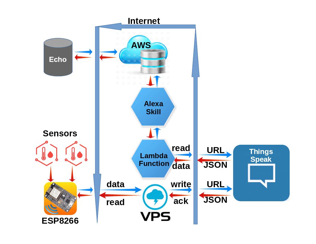
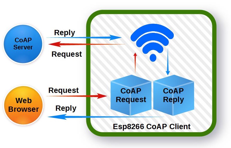
What is needed is a method of converting your verbal request into a command that can be sent to your ESP8266 (or other IoT device) to get the requested information, and to return the information to Alexa in a format that she can read back to you.

The solution presented here uses the Amazon Web Services (AWS) to do all the voice interfacing with Alexa, Things Speak as a repository for the ESP8266 sensor data, and a VPS CRON script to move the sensor data from the ESP8266 to Things Speak.

You might wonder why a VPS and Thing Speak are used. Why not communicate directly with the ESP8266 from the AWS Lambda Function?

Truth is, you can cut out these intermediate steps. But for security, I have added this layer to hide my IoT credentials within my heavily fortified Virtual Private Server (VPS). But do not be concerned, as you will see, this does not make the system overly complicated.

System Diagram

Test Scenario

We start with a voice command: “Alexa, ask ESP8266-12 for the indoor temperature”

Alexa responds with: “The indoor temperature is 73.2 degrees”

So what just happened?

Since we are dealing with the Amazon Echo device, Amazon lingo is needed (bold).

The voice command was received by the Amazon Echo device and recognized as an Alexa skill.

Invocation of the skill triggered the Lambda function which, in-turn, sent a request to ThingSpeak for the current ESP8266 sensor readings,

The readings returned were passed back to the Alexa skill which recites the values of the temperature sensors.

Implementation

We need three components to make this system function as intended.

Data Source (ESP8266 Sensor Data)

  • From ThingSpeak Channel or
  • Directly from ESP8266

Amazon Skill to convert your voice to a command to retrieve the requested information

Amazon Lambda function to receive the Skill request, query for the requested information and return a reply to the Amazon Skill

Let’s do it…

You will need to setup two accounts with Amazon, If you do not already have these accounts, create them now. No worries, they are FREE:

Create Amazon Developer Account (For Alexa Skill)

Start by pointing your browser to:

https://developer.amazon.com/

Select “Sign In” located on the page’s top-right header:

Next, select the “Create your Amazon Developer Account” button

Follow the instructions to create your free Amazon Developer Account

Create free AWS account (For Lambda Function)

Start by pointing your browser to:

https://portal.aws.amazon.com/billing/signup#/start

Follow the instructions to create your free AWS (Amazon Web Services) Account

Creating the Alexa Skill

Sign in to https://developer.amazon.com/ and go to the Developer Console.

Select the Alexa tab.

Select “Get Started” Alexa Skills Kit.

Select “Add a New Skill”

Note: The rest of the skill creation can be customized for your needs. It is suggested that you follow along with this guide for your first skill, and customize after getting this example to work. For this example, my publicly shared ThingSpeak Channel is used for the dynamic data source

For the first tab (Skill information), enter:

Name: ESP8266

Invocation Name: e s p eighty two sixty six dash twelve

Then click “Save” at the bottom.

For the Interaction Model tab, enter:

Intent Schema (copy/paste):


  1. {
  2. "intents": [
  3. {
  4. "slots": [
  5. {
  6. "name": "Sensor",
  7. "type": "ESP_SENSORS"
  8. }
  9. ],
  10. "intent": "GetEspInfoIntent"
  11. },
  12. {
  13. "intent": "AMAZON.HelpIntent"
  14. },
  15. {
  16. "intent": "AMAZON.StopIntent"
  17. },
  18. {
  19. "intent": "AMAZON.CancelIntent"
  20. }
  21. ]
  22. }

Custom Slot Types:

Enter Type: ESP_SENSORS
Enter Values:
every
indoor
outdoor
attic

Then click “Add” below the “Enter Values” box..

Now click “Save” at the bottom.

Sample Utterances: GetEspInfoIntent for {Sensor} temperature

Click “Save” at the bottom.

Then click “Next” at the bottom.


Creating the Lambda Function

Sign in to https://portal.aws.amazon.com

Make sure you are on the URL https://console.aws.amazon.com

From the Console, select Services > Compute > Lambda

Click “Create Function”

Click “Author from scratch”.

Enter the following Basic Information:

Name: ESP8266V2

Role: Create new role from templates

RoleName: myEspRole

Policy Templates: CloudFormation stack read-only permissions

Then click “Create Function”

Select Runtime: “Node.js 4.3”

Then paste the following code in the index.js field:


  1. /**
  2. Copyright 2014-2015 Amazon.com, Inc. or its affiliates. All Rights Reserved.
  3. Licensed under the Apache License, Version 2.0 (the "License"). You may not use this file except in compliance with the License. A copy of the License is located at
  4. http://aws.amazon.com/apache2.0/
  5. or in the "license" file accompanying this file. This file is distributed on an "AS IS" BASIS, WITHOUT WARRANTIES OR CONDITIONS OF ANY KIND, either express or implied. See the License for the specific language governing permissions and limitations under the License.
  6. */
  7. /*
  8. This file has been modified under the terms of the above license October 2017
  9. */
  10. /**
  11. * This code is dependant on data retreived from a ThingsSpeak channel
  12. * It is a Lambda function for handling Alexa Skill requests.
  13. *
  14. * Examples:
  15. * One-shot model:
  16. * User: "Alexa, ask ESP8266 for temperature readings"
  17. * Alexa: "Indoor temperature is 75.2 degrees and outdoor temperature is 86.2 degrees"
  18. */
  19. /**
  20. * App ID for the skill
  21. */
  22. var APP_ID = undefined; //OPTIONAL: replace with "amzn1.echo-sdk-ams.app.[your-unique-value-here]";
  23. //var APP_ID = "amzn1.ask.skill.018df58b-9e42-4e0f-927c-fd06ba2edb5b"; //OPTIONAL: replace with "amzn1.echo-sdk-ams.app.[your-unique-value-here]";
  24. /**
  25. * The AlexaSkill prototype and helper functions
  26. */
  27. var AlexaSkill = require('./AlexaSkill');
  28. var https = require('https');
  29. //ThingSpeak Data Access
  30. var channel_id = 33251;                        //ThingSpeak Channel ID
  31. var speak_key = '9VGQ4X79MQJC90RD';            //ThingSpeak Channel Read Key
  32. var p_at,p_ou,p_in;                            //Sensor Readings
  33. // Create URL to retrieve latest temperature reading from my ThingsSpeak channel (JSON format)
  34. var url = 'https://api.thingspeak.com/channels/' + channel_id + '/feed/last.json?api_key=' + speak_key;
  35. /**
  36. * ESP8266 is a child of AlexaSkill.
  37. * To read more about inheritance in JavaScript, see the link below.
  38. *
  39. * @see https://developer.mozilla.org/en-US/docs/Web/JavaScript/Introduction_to_Object-Oriented_JavaScript#Inheritance
  40. */
  41. var Esp8266 = function () {
  42. AlexaSkill.call(this, APP_ID);
  43. };
  44. // Extend AlexaSkill
  45. Esp8266.prototype = Object.create(AlexaSkill.prototype);
  46. Esp8266.prototype.constructor = Esp8266;
  47. Esp8266.prototype.eventHandlers.onSessionStarted = function (sessionStartedRequest, session) {
  48. //console.log("onSessionStarted requestId: " + sessionStartedRequest.requestId + ", sessionId: " + session.sessionId);
  49. // any initialization logic goes here
  50. };
  51. Esp8266.prototype.eventHandlers.onLaunch = function (launchRequest, session, response) {
  52. //console.log("onLaunch requestId: " + launchRequest.requestId + ", sessionId: " + session.sessionId);
  53. handleEsp8266Request(response);
  54. };
  55. /**
  56. * Overridden to show that a subclass can override this function to teardown session state.
  57. */
  58. Esp8266.prototype.eventHandlers.onSessionEnded = function (sessionEndedRequest, session) {
  59. //console.log("onSessionEnded requestId: " + sessionEndedRequest.requestId + ", sessionId: " + session.sessionId);
  60. // any cleanup logic goes here
  61. };
  62. Esp8266.prototype.intentHandlers = {
  63. "GetEspInfoIntent": function (intent, session, response) {
  64. var speechOutput;
  65. var cardTitle;
  66. var sensorSlot = intent.slots.Sensor,
  67. sensorName = "every";
  68. if (sensorSlot && sensorSlot.value){
  69. sensorName = sensorSlot.value.toLowerCase();
  70. }
  71. switch(sensorName) {
  72. default:
  73. case "every":
  74. speechOutput = "Indoor temperature is " + p_in + " degrees" +
  75. " and the Outdoor temperature is " + p_ou + " degrees and " +
  76. "the Attic temperature is " + p_at + " degrees";
  77. cardTitle = "Temperature Readings";
  78. break;
  79. case "indoor":
  80. speechOutput = "Indoor temperature is " + p_in + " degrees";
  81. cardTitle = "Indoor Temperature Reading";
  82. break;
  83. case "outdoor":
  84. speechOutput = "Outdoor temperature is " + p_ou + " degrees";
  85. cardTitle = "Outdoor Temperature Reading";
  86. break;
  87. case "attic":
  88. speechOutput = "Attic temperature is " + p_at + " degrees";
  89. cardTitle = "Attic Temperature Reading";
  90. break;
  91. }
  92. response.tellWithCard(speechOutput, cardTitle, speechOutput);
  93. },
  94. "AMAZON.HelpIntent": function (intent, session, response) {
  95. response.ask("You can say ask ESP8266 for indoor temperature, or, you can say exit... What can I help you with?", "What can I help you with?");
  96. },
  97. "AMAZON.StopIntent": function (intent, session, response) {
  98. var speechOutput = "Goodbye";
  99. response.tell(speechOutput);
  100. },
  101. "AMAZON.CancelIntent": function (intent, session, response) {
  102. var speechOutput = "Goodbye";
  103. response.tell(speechOutput);
  104. }
  105. };
  106. /* -------------------------------------------------------------
  107. * Get all sensors temperatures and return speech to the user.
  108. * -------------------------------------------------------------
  109. */
  110. function handleEsp8266Request(response) {
  111. // Create speech output
  112. var speechOutput = "Greetings, I did not understand what you want. How may I serve you?";
  113. var cardTitle = "Initial Request";
  114. response.tellWithCard(speechOutput, cardTitle, speechOutput);
  115. }
  116. // Create the handler that responds to the Alexa Request.
  117. exports.handler = function (event, context) {
  118. https.get(url, function(res) {
  119. // Get latest sensor data from home IoT SoC
  120. res.on('data', function(d) {
  121. p_in = JSON.parse(d).field1;
  122. p_ou = JSON.parse(d).field2;
  123. p_at = JSON.parse(d).field3;
  124. // Create an instance of the SpaceGeek skill.
  125. var Esp8266_skill = new Esp8266();
  126. Esp8266_skill.execute(event, context);
  127. });
  128. res.on('end', function() {
  129. });
  130. res.on('error', function(e) {
  131. context.fail("Got error: " + e.message);
  132. });
  133. });
  134. };

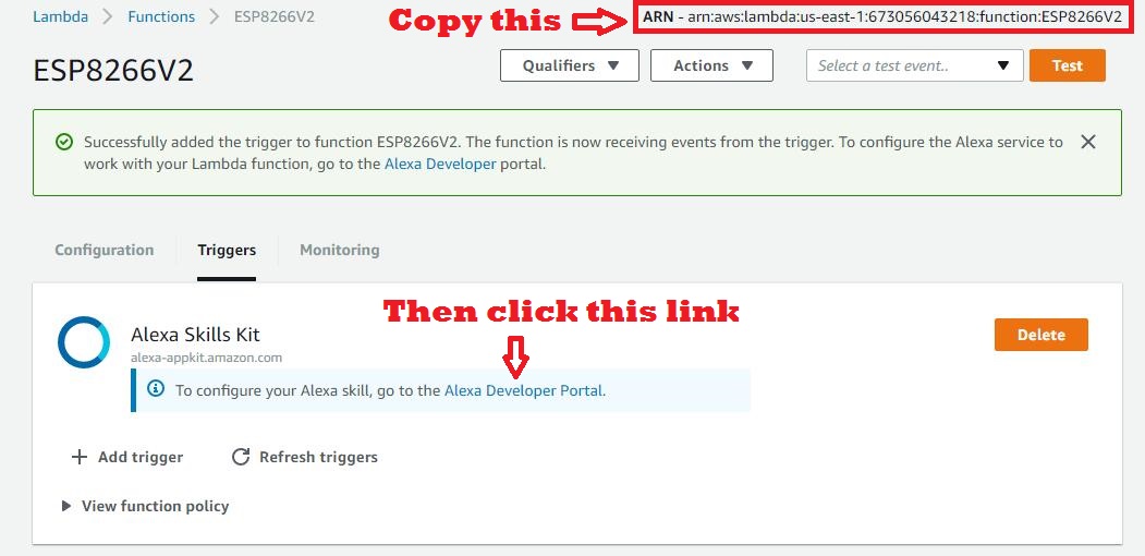
Now save this function (Click “Save and test”)

Exit out of the “Test” screen and click on the “Triggers” tab

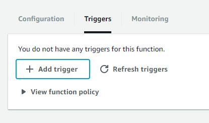
Then click “Add Trigger” and click in the dotted box:

Select “Alexa Skills Kit”:

And click “Submit”.

Now Lets link the Lambda Function to the Alexa skill:

Return to the Alexa Skill developed earlier:

Click Alexa Skills Kit > Get Started

Click on the Name of the Skill created earlier

Click “Configuration”

Click the Endpoint “AWS Lambda ARN” radio button

Paste the ARN from the paste buffer in the “Default” box

Click bottom “Save” button

That’s it!

Now let’s test it…

The next tab on the Alexa Skills page is called “Test”. Select it and scroll down to the “Service Simulator”

Using the “Text” table, simply enter one of the following utterances, click “Ask ESP8266” and verify you get an appropriate “Service Response”:

every temperature
indoor temperature
outdoor temperature
attic temperature

For example, the utterance “attic temperature” should produce the following Service Response in JSON format:


  1. {
  2. "version": "1.0",
  3. "response": {
  4. "outputSpeech": {
  5. "text": "Attic temperature is 49.2 degrees",
  6. "type": "PlainText"
  7. },
  8. "card": {
  9. "content": "Attic temperature is 49.2 degrees",
  10. "title": "Attic Temperature Reading"
  11. },
  12. "speechletResponse": {
  13. "outputSpeech": {
  14. "text": "Attic temperature is 49.2 degrees"
  15. },
  16. "card": {
  17. "content": "Attic temperature is 49.2 degrees",
  18. "title": "Attic Temperature Reading"
  19. },
  20. "shouldEndSession": true
  21. }
  22. },
  23. "sessionAttributes": {}
  24. }

The actual temperature readings will vary, depending on the current temperature in my attic.

You should now be able to invoke this skill using your Amazon Echo using voice commands.

You can verify that this new skill is enabled on your Alexa echo at https://alexa.amazon.com

Select “Skills” and then “Your Skills”. This new skill should be listed and enabled.

The rest of the system has been covered in previous blog posts:

Things Speak Channel:

  • Write values
  • Read Values

Refer to my ThingSpeak Channel

Virtual Private Server (VPS):

  • Read from ESP8266
  • Write to Things Speak

Uses a Linux CRON script scheduled to run at the start of every hour.

See this post: PHP Script to move ESP8266 data

ESP8266 Sensor data source:

  • Read Sensors Continuously
  • Send Sensor Values on request as JSON string

ESP8266 Temperature Sensor Project

In Conclusion

As you can see, you can make the information collected by your IoT device, such as an ESP8266 accessible via audio commands/responses using the Amazon Echo device. The commands and responses can be customized to the exact words you wish to use. This opens up infinite possibilities.

Hope you find this information useful and fun to explore.

Loading

Share This:
FacebooktwitterredditpinterestlinkedintumblrFacebooktwitterredditpinterestlinkedintumblr

MQTT for App Inventor – Adding TLS Security

This article adds TLS security as a connection option to my original MQTT App Inventor project. The addition is relatively straight-forward.  The App already had the ability to configure MQTT connection and message parameters. Adding the TLS option was a simple matter of adding a check-box to the configuration screen and modifying the JavaScript code used to communicate with MQTT.

Here are a few of my past posts for review. They are related to MQTT and TLS connections:

Now lets update the App Inventor project to support TLS connections to an MQTT broker. Since this article only covers the updates needed to support TLS, it is recommended that the initial project article be reviewed in case anything is unclear.

And if you want to jump ahead and have a look at the project, here it is.

Updating the Configuration GUI

Since the choice is binary, that is, we either want to connect using a TLS or a non-TLS MQTT channel, the GUI selection is obvious; a checkbox. This was added to the top of the configuration screen. You can customize the position if desired.

Updating the Configuration File

We use the same configuration file as the original project. Each configuration parameters is stored in this file as a JSON string. The file resides on our target Android device. The checked/unchecked state of our added checkbox gets saves in the JSON object as a “true” or “false” string.

The TLS connection option is added at the bottom of the configuration file (cfg.txt).


  1. {
  2. "mqtt_broker":"yourmqttbrokerdomain",
  3. "mqtt_txtopic":"mqtt_request",
  4. "mqtt_rxtopic":"mqtt_reply",
  5. "mqtt_un":"user2",
  6. "mqtt_pw":"user2",
  7. "mqtt_port":"8083",
  8. "mqtt_clientId":"clientID",
  9. "mqtt_keepalive":"60",
  10. "mqtt_lastWillTopic":"lwt",
  11. "mqtt_lastWillMessage":"closing down....",
  12. "mqtt_lastWillQoS":"0"",
  13. "mqtt_TLS_enable":"true"
  14. }

Updating the JavaScript

The JavaScript used to interface with the MQTT broker is the final but most important element of this update. Just as in the original App, the JSON  string containing the MQTT connection parameters is sent to the JavaScript using the App Inventor “WebViewString” feature.

Just as before, our custom JavaScript behaves as a “Wrapper” server, which communicates with the open-source MQTT 3.1.1 WebSocket API (mqttws31.js). Again, if this is unclear, please review my original project description.

The custom JavaScript code is stored in the file “mqtt_appinventor_paho.html”. Adding the TLS connection option required only one new line of code:


  1.   connectOptions.useSSL = cfgpar.mqtt_TLS_enable == "true";

That is the power of JSON.

The configuration file received via “WebViewString” from the App Inventor App can be parsed by parameter name (cfgpar.mqtt_TLS_enable). If the string is set to “true”, the connect option “useSSL” is enabled. If the string is not set to “true”, then the “useSSL” option is disabled. connectOption.useSSL is built into the open-source MQTT Websocket API.

That’s it!

The updated App Inventor project is accessible on GitHub here.

Testing the Update

When testing this update, it is important to remember to configure the MQTT port to one that is known to support TLS connections.Since this App is designed to communicate with an ESP8266 via an MQTT broker, it is recommended to test the App using the ESP8266 and MQTT broker from these posts:

But if you simply wish to verify the MQTT connection, any MQTT client can be used. My favorite is the web-based HiveMQTT client.

In Closing

There  you have it. Secure TLS MQTT connections in an App Inventor project. Hope you find this feature useful.

Loading

Share This:
FacebooktwitterredditpinterestlinkedintumblrFacebooktwitterredditpinterestlinkedintumblr

ESP8266 SSL/TLS MQTT Connection

Securing your IoT things is critical. MQTT connections are definitely at risk. But simply using username/password combinations for your MQTT connection is NOT secure.

Why not?

Well, even with passwords, everything sent over the Internet is unencrypted…open for any and all prying eyes to see…and possible maliciously manipulate.

Fortunately, we can solve that problem by creating TLS connections for secure MQTT data transfers. And yes, this encryption layer can even be brought to the ESP8266 platform.

But it does come at a cost…a huge bite out  of the limited ESP RAM heap. With grave consequences. I certainly experienced catastrophic results during in my initial attempts. Finally, and after several iterations, the implementation presented here now manages the heap successfully. Using this approach, we achieve the desired results…a  stable, reset-free ESP8266 platform with a secure interface to an MQTT broker.

Cutting to the Chase

At this point, if you would like to jump in without the benefit of additional explanation, please find the code for this Arduino 1.8.2 IDE compiled project here.

Compiler Issue

The first step towards adding TLS to the ESP8266 framework was to access a secure MQTT Broker. Installation of a TLS MQTT Broker was presented in my last post. After setting up the TLS MQTT broker on a VPS host, the next step was to update the ESP8266 IoT platform developed previously to support the secure connection. This required the addition of a new class to the project; WiFiClientSecure. This class supports secure TCP connections.

But I soon discovered the first problem…

You see, the project simply would not compile with the introduction of this class.

Through much research and frustration, I finally discovered the root cause of the problem and better yet, a solution.

As it turned out, one of the compiler flags used by the Arduino IDE was incompatible with the new WiFiClientSecure class library, and had to be   revised. While your computer may have a different path to the compiler options file, mine was located on a Windows 10 PC at:

C:\Users\owner\AppData\Local\Arduino15\packages\esp8266\hardware\esp8266\2.2.0\platform.txt

Here is the line that needs to be changed in order to compile the project:


  1. #OLD: compiler.c.elf.libs=-lm -lgcc -lhal -lphy -lpp -lnet80211 -llwip -lwpa -lcrypto -lmain -lwps -lsmartconfig -lmesh <span style="color: #ff0000;">-lssl</span>
  2. #NEW: compiler.c.elf.libs=-lm -lgcc -lhal -lphy -lpp -lnet80211 -llwip -lwpa -lcrypto -lmain -lwps -lsmartconfig -lmesh <span style="color: #ff0000;">-laxtls</span>

A Heap of Trouble

After a successful compilation and upload to my development ESP8266 hardware, I soon discovered that the TLS connection consumed a huge chunk of the ESP heap (RAM). Somewhere between 12 and 15 kB. This was such a big resource hog that the ESP8266 would reset anytime a TLS MQTT connection was attempted.

And I also discovered that the configuration screen also used a large amount of ESP heap. That was because, even though the page’s HTML was stored in program memory as a constant, it had to be brought into the heap for run-time modifications before the page was rendered.

These two processes, ESP configuration and TLS MQTT connection negotiation were fighting for the same limited heap space. While each process would work on its own, they simply could not both exists at the same time.

So the project was modified to start up in one of two modes:

  1. Configuration Mode – Sets unique ESP8266 operational parameters
  2. MQTT Connection Mode – Connects to TLS Sensor and continuously reads sensors

Start-up Mode

Upon power-up, the ESP8266 had to know which mode to start up in. That would limit the heap usage to the requirements of the selected mode. This was implemented as a EEPROM location that is read in the programs setup() function.


  1. SetSysCfgFromEeprom(); // Set Session Cfg from EEPROM Values

Two EEPROM locations are now used for MQTT initialization.


  1. GetEepromVal(&amp;Param, EEPROM_MQTTSSLEN, EEPROM_CHR);
  2. mqtt_ssl_enable = os_strcmp(Param.c_str(), "true")==0;
  3. GetEepromVal(&amp;Param, EEPROM_MQTTCLEN, EEPROM_CHR);
  4. mqtt_cl_enable = os_strcmp(Param.c_str(), "true")==0;

If MQTT is configured to be enabled (mqtt_cl_enable), then the second parameter (mqtt_ssl_enable) is used to determine whether a TLS connection (sslClient) or a standard connection (espClient) is to be used at ESP8266 startup:


  1. if(mqtt_cl_enable) {
  2. client = mqtt_ssl_enable ? new PubSubClient(sslClient) : new PubSubClient(espClient);
  3. MqttServer_Init(); // Start MQTT Server
  4. }

These two parameters are set within the operational mode that the ESP8266 is currently operating.

Identifying the Start-up Mode

There are two methods to determine which mode the ESP8266 start up running. You can either look at the start-up output from the serial port or query the ESP8266.

Configuration Mode with Web Server:
The start-up output will include the following if the ESP has started up in configuration mode, with the web server running:

ESP8266 IP: 192.168.0.133
ESP8266 WebServer Port: 9705
ESP8266 Mode: Web Server Running – Type = SDK API

Of course, the port and IP values may vary if they are configured differently.

MQTT Mode:
The start-up output will include the following if the ESP has started up in MQTT Mode:

MQTT Rx Topic: mqtt_rx_18fe34a26629
MQTT Tx Topic: mqtt_tx_18fe34a26629
ESP8266 Mode: MQTT Client Running

Note the MQTT topics are provided. These values need to be known in order to communicate with the ESP, which acts like a server for this project.

Start-up Mode Query
The start-up mode can also be determined from the response to a query. This method may be preferred for applications that do not have access to the ESP serial port or are using the serial link for other purposes.

The ESP will not respond if it is not running in the queried mode. For configuration mode, simply enter the configuration URL (or any other valid web server URL). If the ESP responds, it is running in this mode.

Likewise, attempt to send a message to the ESP MQTT  “server”. If is running in MQTT mode if a response is received

Configuration Mode

The configuration screen from the last iteration of this project was modified to add the new MQTT parameters. Just as before, this screen is accessed by entering the ESP8266 IP (or domain name) with it’s assigned web server port with the following suffix :

http://192.168.0.133:9705/config

If you want to switch to the TSL MQTT operating mode at power-up, just check the 2 new boxes, click SAVE, and then RESET ESP8266.

A URL has also been provided to switch modes within your application code:

http://192.168.0.133:9705/?request=MqttSslOn

This will change the EEPROM content to switch modes and reset the ESP8266 so it starts-up in the selected mode.

MQTT Mode

When the ESP8266 starts up in MQTT mode with TLS connection enabled, it will respond to server requests just like it did in the last iteration of this project. And switching back to ESP web server/configuration mode is simply a matter of sending the request in an MQTT message:

/?request=HttpOn

Conclusion

We now have a secure MQTT connection to the ESP8266. Here is the project code link again. And with careful management of the RAM (heap), it will perform reliably. More functionality in this case requires the distribution of tasks between two operating modes which are only loaded in memory when needed. This technique can be used in other cases as well to stretch the capabilities of this amazing little system on a chip (SoC) we call ESP8266.


Loading

Share This:
FacebooktwitterredditpinterestlinkedintumblrFacebooktwitterredditpinterestlinkedintumblr

VPS Application 1: MQTT Broker

Using an MQTT Broker to publish and subscribe to IoT events is a critical aspect of many IoT infrastructures. And hosting your own broker retains complete control in your hands. This writing provides step-by-step instructions for installing the Mosquitto MQTT broker on a VPS running Linux Ubuntu 16.04.

Don’t have a personal Virtual Private Server (VPS)? Check here  to find out how to get one.

MQTT Broker Installation Overview

Installing the Mosquitto MQTT broker on your Linux Ubuntu VPS can be broken down into 3 basic steps. And if you wish to also provide secure connections, four additional steps are needed.

  1. Install Mosquitto
  2. Configuring MQTT Passwords
  3. Configuring MQTT Over Websockets
  4. Securing your MQTT Broker
    1. Install Certbot
    2. Run Cerbot
    3. Setting up Certbot Automatic Renewals
    4. Configuring MQTT SSL

Installing Mosquitto

A  telnet client is needed to install and configure the MQTT broker on your VPS. PuTTY is a widely used telnet client. It can be downloaded here. Make sure you have a telnet client installed and your non-root linux user credentials are handy before continuing.

Then, log in with your non-root user with PuTTY and install Mosquitto with apt-get by entering:

sudo apt-get install mosquitto mosquitto-clients

The MQTT broker service will start automatically after the installation has completed. To test, open a second command-line interface (CLI) using PuTTY. With one of the terminal windows, subscribe to a test topic named “mymqtttesttopic” by entering:

mosquitto_sub -h localhost -t mymqtttesttopic

Then, publish a message from the other terminal:

mosquitto_pub -h localhost -t mymqtttesttopic -m “Sent from my own MQTT Broker”

If the installation is properly working, the subscribe terminal will receive the message:

Configuring MQTT Passwords

First level of security is to configure Mosquitto to use passwords. Mosquitto includes a utility to generate a special password file called mosquitto_passwd. Using this utility, you will be prompted to enter a password for the specified username, and place the results in /etc/mosquitto/passwd. From the terminal, enter:

sudo mosquitto_passwd -c /etc/mosquitto/passwd testuser

Note: Use “password” for the password for this test case when prompted

Now we’ll open up a new configuration file for Mosquitto and tell it to use this password file to require logins for all connections:

sudo nano /etc/mosquitto/conf.d/default.conf

This should open an empty file. Paste in the following:

/etc/mosquitto/conf.d/default.conf
allow_anonymous false
password_file /etc/mosquitto/passwd

allow_anonymous false will disable all non-authenticated connections, and the password_file line tells Mosquitto where to look for user and password information. Save and exit the file.

Now we need to restart Mosquitto and test our changes:

sudo systemctl restart mosquitto

Try to publish a message without a password:

mosquitto_pub -h localhost -t “test” -m “hello world”

The message should be rejected:

Output
Connection Refused: not authorized.
Error: The connection was refused.

Before we try again with the password, switch to your second terminal window again, and subscribe to the ‘test’ topic, using the username and password this time:

mosquitto_sub -h localhost -t test -u “testuser” -P “password

It should connect and sit, waiting for messages. You can leave this terminal open and connected for the rest of the tutorial, as we’ll periodically send it test messages.

Now publish a message with your other terminal, again using the username and password:

mosquitto_pub -h localhost -t “test” -m “hello world” -u “testuser” -P “password

The message should be passed from one terminal to the other in the same way as the initial test without passwords. If the message was received, we have successfully added password protection to our Mosquitto MQTT Broker.

Passwords for multiple users

Most likely, your MQTT broker will need to support more than one user. Here is how to create a password file for multiple users:

First create a plain text file, adding a line for each user: <username>:<password>

sudo nano /etc/mosquitto/passwd

For 3 users, the file contents:

username1:password1
username2:password2
username3:password3

Then encrypt the plain text file by entering:

sudo mosquitto_passwd -U /etc/mosquitto/passwd

Configuring MQTT Over Websockets

You will probably want to have your MQTT Broker support Websockets. This makes it possible to communicate with your MQTT broker using JavaScript. Very useful for web applications. Here is how to add it to your Mosquitto configuration.

Open the configuration file to add port listeners:

sudo nano /etc/mosquitto/conf.d/default.conf

Add to the bottom of the file:

listener 1883 localhost

listener 8883

listener 8083
protocol websockets

listener 18083
protocol websockets

Then update the firewall to support these listener ports.

sudo ufw allow 8883
sudo ufw allow 8083
sudo ufw allow 18083

Restart Mosquitto to activate the listener configuration:

sudo systemctl restart mosquitto

Here is the MQTT port allocation:

Usage
1883 Standard TCP/IP Port
8883 Secure SSL TCP/IP Port
8083 Secure Websockets Port
18083 Insecure Websockets Port

Note that the last listener on port 18083 is not a standard MQTT port. This port is used for insecure (non-encrypted connections). While it is not required, it can sometimes be useful when communicating with tiny IoT devices that cannot support the additional overhead required to connect using the SSL protocol.

Testing MQTT Websockets

The easiest method of verifying the Websockets ports is to use a web browser MQTT client. While there are many such tools available, HiveMQ will be used for this demonstration.

First, open an incognito web browser window to this link.

Note: You must use an incognito window. A normal browser window sends extra information to track your browsing history. This extra http traffic will interfere with the MQTT websocket protocol and cause the connection to fail.

And create a new connection:

Once the connection is made, publish a test message:

Securing your MQTT Broker

There are four steps required to securing the MQTT Broker with SSL/TLS.

Step 1: Install Certbot

We must first install the official client from an Ubuntu PPA, or Personal Package Archive. These are alternative repositories that package more recent or more obscure software. First, add the repository from the VPS terminal.

sudo add-apt-repository ppa:certbot/certbot

Note: If this command is not found, the following package needs to be installed first:

sudo apt-get install software-properties-common

You’ll need to press ENTER to accept. Afterwards, update the package list to pick up the new repository’s package information.

sudo apt-get update

And finally, install the official Let’s Encrypt client, called certbot.

sudo apt-get install certbot

Now that we have certbot installed, let’s run it to get our certificate.

Step 2: Run Certbot

The Certbot that was just installed needs to answer a cryptographic challenge issued by the Let’s Encrypt API in order to prove we control our domain. It uses ports 80 (HTTP) and/or 443 (HTTPS) to accomplish this. We’ll only use port 80, so let’s allow incoming traffic on that port now:

sudo ufw allow http

Output
Rule added

We can now run Certbot to get our certificate. We’ll use the --standalone option to tell Certbot to handle the HTTP challenge request on its own, and --standalone-supported-challenges http-01 limits the communication to port 80. -d is used to specify the domain you’d like a certificate for, and certonly tells Certbot to just retrieve the certificate without doing any other configuration steps.

sudo certbot certonly –standalone –standalone-supported-challenges http-01 -d mqtt.example.com

When running the command, you will be prompted to enter an email address and agree to the terms of service. After doing so, you should see a message telling you the process was successful and where your certificates are stored.

We’ve got our certificates. Now we need to make sure Certbot renews them automatically when they’re about to expire.

Step 3: Setting up Cerbot Automatic Renewals

Let’s Encrypt’s certificates are only valid for ninety days. This is to encourage users to automate their certificate renewal process. We’ll need to set up a regularly run command to check for expiring certificates and renew them automatically.

To run the renewal check daily, we will use cron, a standard system service for running periodic jobs. We tell cron what to do by opening and editing a file called a crontab.

sudo crontab -e

You’ll be prompted to select a text editor. Choose your favorite, and you’ll be presented with the default crontab which has some help text in it. Paste in the following line at the end of the file, then save and close it.

crontab
. . .
15 3 * * * certbot renew --noninteractive --post-hook "systemctl restart mosquitto"

The 15 3 * * * part of this line means “run the following command at 3:15 am, every day”. The renewcommand for Certbot will check all certificates installed on the system and update any that are set to expire in less than thirty days. --noninteractive tells Certbot not to wait for user input.

--post-hook "systemctl restart mosquitto" will restart Mosquitto to pick up the new certificate, but only if the certificate was renewed. This post-hook feature is what older versions of the Let’s Encrypt client lacked, and why we installed from a PPA instead of the default Ubuntu repository. Without it, we’d have to restart Mosquitto every day, even if no certificates were actually updated. Though your MQTT clients should be configured to reconnect automatically, it’s wise to avoid interrupting them daily for no good reason.

Now that automatic certificate renewal is all set, we’ll get back to configuring Mosquitto to be more secure.

Step 4. Configuring MQTT SSL

To enable SSL encryption, we need to tell Mosquitto where our Let’s Encrypt certificates are stored. Open up the configuration file we previously started:

sudo nano /etc/mosquitto/conf.d/default.conf

Replace the file content with the following:


  1. allow_anonymous false
  2. password_file /etc/mosquitto/passwd
  3. listener 1883 localhost
  4. listener 8883
  5. certfile /etc/letsencrypt/live/&lt;yourVPSdomainname&gt;/cert.pem
  6. cafile /etc/letsencrypt/live/&lt;yourVPSdomainname&gt;/chain.pem
  7. keyfile /etc/letsencrypt/live/&lt;yourVPSdomainname&gt;/privkey.pem
  8. listener 8083
  9. protocol websockets
  10. certfile /etc/letsencrypt/live/&lt;yourVPSdomainname&gt;/cert.pem
  11. cafile /etc/letsencrypt/live/&lt;yourVPSdomainname&gt;/chain.pem
  12. keyfile /etc/letsencrypt/live/&lt;yourVPSdomainname&gt;/privkey.pem
  13. listener 18083
  14. protocol websockets
This file is the same as the last version, except the SSL certificates have been added to the SSL and websocket ports:
 
 
  1. certfile /etc/letsencrypt/live/&lt;yourVPSdomainname&gt;/cert.pem
  2. cafile /etc/letsencrypt/live/&lt;yourVPSdomainname&gt;/chain.pem
  3. keyfile /etc/letsencrypt/live/&lt;yourVPSdomainname&gt;/privkey.pem

listener 8883 sets up an encrypted listener on port 8883. This is the standard port for MQTT + SSL, often referred to as MQTTS. The next three lines, certfile, cafile, and keyfile, all point Mosquitto to the appropriate Let’s Encrypt files to set up the encrypted connections.

Save and exit the file, then restart Mosquitto to update the settings:

sudo systemctl restart mosquitto

Now we test again using mosquitto_pub, with a few different options for SSL:

mosquitto_pub -h <your VPS domainname> -t test -m “hello again” -p 8883 –capath /etc/ssl/certs/ -u “user1” -P “password

Note that we’re using the full hostname instead of localhost. Because our SSL certificate is issued for <yourVPSdomainname>, if we attempt a secure connection to localhost we’ll get an error saying the hostname does not match the certificate hostname (even though they both point to the same Mosquitto server).

--capath /etc/ssl/certs/ enables SSL for mosquitto_pub, and tells it where to look for root certificates. These are typically installed by your operating system, so the path is different for Mac OS, Windows, etc. mosquitto_pub uses the root certificate to verify that the Mosquitto server’s certificate was properly signed by the Let’s Encrypt certificate authority. It’s important to note that mosquitto_pub and mosquitto_sub will not attempt an SSL connection without this option (or the similar --cafile option), even if you’re connecting to the standard secure port of 8883.

If all goes well with the test, we’ll see hello again show up in the other mosquitto_sub terminal.

You can also run additional tests using the HiveMQ MQTT client again to verify the websocket port 8083, which is now configured securely. This time, make sure the “SSL” checkbox is selected when making a connection.

Once this final test has been performed successfully, your MQTT broker is fully set up!

In Closing

With your own secure MQTT broker running on a VPS, you have a powerful platform at your disposal. Using a reliable provider, you no longer need to keep any hardware running 24-7, no longer vulnerable to power interruptions or computer crashes. And there are no constraints on your custom configuration options. That is all taken care of by the VPS provider.

I hope you find this information useful

Loading

Share This:
FacebooktwitterredditpinterestlinkedintumblrFacebooktwitterredditpinterestlinkedintumblr

Your Own VPS for IoT and More

Having a Virtual Private Server (VPS) at your disposal opens up boundless IoT possibilities – all under your direct control – with no reliance on third-party cloud services. Like hosting your own MQTT broker, CoAP server, and scheduling periodic tasks to monitor and control your IoT devices or store/retrieve information using a database. Website hosting, including popular CMS sites such as WordPress, Joomla!, Drupal and more as well as file/picture sharing are also possible with your VPS.

Does this seem like a daunting task? Difficult to set-up? And expensive?

It doesn’t have to be.

Building on a past project, all  I did initially was port my USB Thumb Drive LAMP server to a VPS. And the basic framework, including the Linux distribution  you choose to use, are installed automatically for you. This greatly simplifies the setup…

Shared Host vs VPS

Before moving on with VPS, it should be noted that “Shared Host” are also available. They are tempting as the lowest cost available, they do not provide the capabilities or flexibility of VPS, and thus are not addressed in this post. Here is one decent article I have found that provides clear support for the superiority of VPS over a shared host. You are in control with a VPS, free from the restrictions placed on a shared host account.

Selecting a VPS Provider 

First thing you have to do is select a VPS provider. There are many to choose from. All options I have seen start with a basic package and scale up to fit your needs. For basic DIY IoT enthusiasts, the entry-level offering provides more capability that you should ever need. Here are a few of the VPS providers and their basic features:

Website Cost/month CPU Cores RAM Storage Transfer
LiNode linode.com $5.00 1 1G 20G SSD 1 TB
LiNode linode.com $10.00 1 2G 30G SSD 2 TB
iPage iPage.com $19,99 1 1G 40G 1 TB
HostGator HostGator.com $19,95 2 2G 120G 1.5 TB
FatCow fatcow.com $19,99 1 1G 40G 1 TB
JustHost justhost.com $19,99 2 2G 30G 1 TB
Bluehost bluehost.com $19,99 2 2G 30G SAN 1 TB

I found that the Linode option offered the best value. At 10 USD per month, this provider was the lowest cost of the ones I had looked at. And recently, they have added even a lower, 5 USD per month package. In fact, there were many others that offered teaser rates initially, only to cost much more than the rates listed above. Those providers were eliminated from my consideration.

LiNode uses Solid-State Disks (SSD) which yield lightning fast performance, even with the entry level package that uses a single CPU core. I have been had an active VPS account with LiNode for about a year now, with 100% uptime.

If you do choose to setup a VPS using LiNode, please consider using this link, which, full disclosure, would provide me with a referral credit to help fund my own VPS account and continue sharing information.

Operating System Options 

LiNode VPS provides step-by-step instructions for setting up your system. While I do not have any personal experience, I suspect other VPS providers offer similar directions to simplify the setup procedure. or those familiar with Linux, here are the distributions that LiNode offers for immediate deployment:

I chose to deploy Ubuntu 16.04 LTS, which is a widely used distribution. With that basic configuration, I have customized the setup for my own personal needs.

Exploiting Your VPS Platform 

Once your VPS is setup, it is ripe and ready for practical applications. The first thing many DIY enthusiasts will want to add is a private MQTT broker. As an avid ESP8266, the first 3 applications listed below can interface directly with the VPS. This and other uses for the VPS will be covered in follow-up posts…

  • VPS Application 1: MQTT Broker
  • VPS Application 2: CoAP Server
  • VPS Application 3: Scheduled IoT Monitor/Control Scripts
  • VPS Application 4: Hosting a Website
  • VPS Application 5: Private Email Server

And this is just the beginning.

Hope you find this information useful.

Loading

Share This:
FacebooktwitterredditpinterestlinkedintumblrFacebooktwitterredditpinterestlinkedintumblr

ESP8266 as a CoAP Client

coap1

Several examples can be found to configure the ESP8266 as a CoAP server. Last year I too had developed one. Here is my working example.

But what about using the device as a CoAP client? Using the ESP8266 to send requests to a CoAP server? With a two-ESP8266 module setup, this would provide the capability to set up a CoAP client/server architecture.

While I was unable to find a working example, much to my surprise, it was not that difficult to develop a client from my working server. Here is how it was done…

Turning the tables

After reviewing my ESP8266 CoAP server code, the seeds for a client were obvious. The server listens for CoAP request, acts on it, and sends a reply. To make a client, all that is necessary is to reverse the order.

First, use the server’s reply code to send a request to a server. Then simply listen for a reply from the CoAP server using the “listen” code.

Communication Structure 

This project uses a standard http server to initiate requests to a CoAP server. With this structure, a standard web browser can be used to test the CoAP client functionality.


coap_client


Separate Requests and Replies 

Using http request to initiate a CoAP client request presents a slight complication. That is, I found that checking for a CoAP reply (UDP) from a request while the http (TCP) connection was open caused the ESP8266 to crash. The problem was that the TCP connection callback function blocks the CoAP UDP reply packet. It was stuck waiting until the ESP8266 watchdog timed out, and then… Crash!

One solution is to use an Asynchronous TCP library such as the one found here. But that is beyond the scope of this simple ESP8266 CoAP client project. However, I do intend to explore that option in a future post on this subject.

But for now, it was easier to resolve this problem by breaking down an http GET initiated CoAP communication  exchange into two parts. The first http GET sends a CoAP request to the target CoAP server. After the TCP connection is closed. the CoAP UDP reply is received and stored. A second http GET is then needed to retrieve the CoAP reply.

 Sending a CoAP Request 

A CoAP request is comprised of a UDP packet per RFC7252. This example uses a simple CoAP server installed on a second ESP8266 that supports just 3 actions.

  1. Turn Led On/Off
  2. Blink Led
  3. Get Sensor Values

The CoAP UDP request packets are pre-defined in unique byte arrays:


  1. uint8_t packetbuf_LED_ON[]     = {0x40, 0x03, 0x00, 0x00, 0xB5, 0x6C, 0x69, 0x67, 0x68, 0x74, 0xFF, 0x31};
  2. uint8_t packetbuf_LED_OFF[]    = {0x40, 0x03, 0x00, 0x00, 0xB5, 0x6C, 0x69, 0x67, 0x68, 0x74, 0xFF, 0x30};
  3. uint8_t packetbuf_LED_BLINK[]  = {0x40, 0x03, 0x00, 0x00, 0xBB, 0x6C, 0x69, 0x67, 0x68, 0x74, 0x5F, 0x62, 
  4. 0x6C, 0x69, 0x6E, 0x6B, 0xFF, 0x35};
  5. uint8_t packetbuf_GETSENSORS[] = {0x40, 0x03, 0x00, 0x00, 0xB7, 0x72, 0x65, 0x71, 0x75, 0x65, 0x73, 0x74, 
  6. 0xFF, 0x2F, 0x3F, 0x72, 0x65, 0x71, 0x75, 0x65, 0x73, 0x74, 0x3D, 0x47, 
  7. 0x65, 0x74, 0x53, 0x65, 0x6E, 0x73, 0x6F, 0x72, 0x73};

The first byte (0x40) identifies the CoAP version as 1.0. The ‘0’ in the lower 4 bits indicate no tokens will follow the message header. The second byte (0x03) identifies the CoAP code as 0.03, indicating the PUT method used in the UDP request packet. Bytes 3 and 4 contain the messageID. This value starts at 0 upon ESP8266 startup and is incremented every time a message is sent.

The lower 4 bits identify the packet option length and is followed by the option value. Then, the byte following the option is the payload deliminator, and is set to oxFF.

Size (bytes) Value (Hex) Value(char) Parameter
LED ON 5 6C 69 67 68 74 light 1
LED OFF 5 6C 69 67 68 74 light 0
LED BLINK 11 6C 69 67 68 74 5F 62 6C 69 6E 6B light_blink 0-9
GET SENSORS 72 65 71 75 65 73 74 request /?request=GetSensors

The packet payload, which follows the 0xFF deliminator, contains the request message. As shown in the table above, the parameter is set to 1 to turn the CoAP server ESP8266 circuit LED on and 0 to turn the LED off.

And just as with other web server request, the CoAP requests are sent (udp_send) after an http GET is received.


  1.                 // Send CoAP Request to ESP8266 (192.168.0.141)
  2.                 else if(os_strcmp(pURL_Param-&gt;pParVal[0], "CoAPLedOn")==0) {
  3.                     coaplen = sizeof(packetbuf_LED_ON);
  4.                     incrMessageID(packetbuf_LED_ON);            //Increment Mesaage ID 
  5.                     udp_send(packetbuf_LED_ON, coaplen);
  6.                     payld = "http GET 'CoAPGetReply' required to get CoAP reply"; 
  7.                 }
  8.                 // Send CoAP Request to ESP8266 (192.168.0.141)
  9.                 else if(os_strcmp(pURL_Param-&gt;pParVal[0], "CoAPLedOff")==0) {
  10.                     coaplen = sizeof(packetbuf_LED_OFF);
  11.                     incrMessageID(packetbuf_LED_OFF);          //Increment Mesaage ID 
  12.                     udp_send(packetbuf_LED_OFF, coaplen);
  13.                     payld = "http GET 'CoAPGetReply' required to get CoAP reply"; 
  14.                 }
  15.                 // Send CoAP Request to ESP8266 (192.168.0.141)
  16.                 else if( (os_strcmp(pURL_Param-&gt;pParVal[0], "CoAPLedBlink")==0)&amp;&amp;(os_strcmp(pURL_Param-&gt;pParam[1], "cnt")==0) ) {
  17.                     coaplen = sizeof(packetbuf_LED_BLINK);
  18.                     //Insert Blink Count (1-9)
  19.                     *pURL_Param-&gt;pParVal[1] = (*pURL_Param-&gt;pParVal[1] &lt; 0x31) ? 0x31 : *pURL_Param-&gt;pParVal[1];
  20.                     *pURL_Param-&gt;pParVal[1] = (*pURL_Param-&gt;pParVal[1] &gt; 0x39) ? 0x39 : *pURL_Param-&gt;pParVal[1];
  21.                     packetbuf_LED_BLINK[coaplen-1] = *pURL_Param-&gt;pParVal[1];
  22.                     incrMessageID(packetbuf_LED_BLINK);       //Increment Mesaage ID 
  23.                     udp_send(packetbuf_LED_BLINK, coaplen);   //Send Packet
  24.                     payld = "http GET 'CoAPGetReply' required to get CoAP reply"; 
  25.                }
  26.                 // Send CoAP Request to ESP8266 (192.168.0.141)
  27.                 else if(os_strcmp(pURL_Param-&gt;pParVal[0], "CoAPGetSensors")==0) {
  28.                     coaplen = sizeof(packetbuf_GETSENSORS);
  29.                     incrMessageID(packetbuf_GETSENSORS);     //Increment Mesaage ID 
  30.                     udp_send(packetbuf_GETSENSORS, coaplen);
  31. payld = "http GET 'CoAPGetReply' required to get CoAP reply";
  32.                 }
  33.                 // Send CoAP Request to ESP8266 (192.168.0.141)
  34.                 else if(os_strcmp(pURL_Param-&gt;pParVal[0], "CoAPGetReply")==0) {
  35.                     payld = String(coap_reply_c);
  36.                 }

Receiving the CoAP Reply 

Note in the above code that the CoAP reply is set (payld) after the UDP packet it sent to the CoAP server. But the reply simply states that you must send a ‘CoAPGetReply’ request in order to get the CoAP reply. As noted previously, that is due to the blocking nature of the TCP callback.

The actual reply is stored in the global character string ‘coap_reply_c’.To get the reply, simply send the second GET request:

<ESP_IP>:<ESP_PORT>/?request=CoAPGetReply

Example Transactions

So here is the browser based requests you can use the test this CoAP server. This example assumes the ESP IP is 192.168.0.141 and the TCP port is set to 9706.

URL (192.168.0.141:9706) Suffix http Reply
Set CoAP Server LED Off /?request=CoAPLedOff http GET 'CoAPGetReply' required to get CoAP reply
Set CoAP Server LED Off /?request=CoAPGetReply 0
Set CoAP Server LED On /?request=CoAPLedOn http GET 'CoAPGetReply' required to get CoAP reply
Set CoAP Server LED On /?request=CoAPGetReply 1
Set CoAP Server LED Blinking 3 times /?request=CoAPLedBlink&cnt=3 http GET 'CoAPGetReply' required to get CoAP reply
Get CoAP Server Sensor Values /?request=CoAPGetSensors http GET 'CoAPGetReply' required to get CoAP reply
Get CoAP Server Sensor Values /?request=CoAPGetReply { "Ain0":"142.00", "Ain1":"143.00", "Ain2":"143.00", "Ain3":"145.00", "Ain4":"144.00", "Ain5":"145.00", "Ain6":"144.00", "Ain7":"140.00", "SYS_Heap":"32896", "SYS_Time":"37" }

This project’s GitHub Repository 

In Closing 

There you have it. A simple ESP8266 CoAP client structure to use in your custom application. But this is just a starting framework. There are obvious enhancements that can be made to this working example. Here are some of the things I would do next…

  1. Add web configurable options – Example
  2. Revise to support Async TCP
  3. Implementation of additional RFC7252 options

Hope you find this information useful…

Loading

Share This:
FacebooktwitterredditpinterestlinkedintumblrFacebooktwitterredditpinterestlinkedintumblr

MQTT for App Inventor – More Configurable Settings

configs

More MQTT Configurable Parameters via App Inventor

My last post on this subject introduced a few configurable setting to an MQTT App Inventor project. It was a no frills, bare bones version. But a few essential parameters were  left out. This article fills in the some of the gaps, including connection authentication, websocket port assignment, timeout, last will and testimonial, and the clientID. With this update, the following MQTT settings become configurable:

  • MQTT Broker domain name
  • Request Topic
  • Reply Topic
  • User Name (Leave Blank if not used)
  • Password (Leave Blank if not used)
  • MQTT Websocket Port
  • Client ID
  • Keep Alive Timeout (seconds)
  • Last Will Topic
  • Last Will Message
  • Last Will QoS

NOTE: If you want to skip the implementation details presented below and simply use this project now, it is available on GitHub here.

A New Client Library

My initial App Inventor MQTT project used the Mosquitto client library. While that was great for developing the “proof-of-concept”, demonstrating that you could indeed link an App Inventor project to an MQTT broker, some serious shortcomings soon became evident.

When attempting to refine the project to support broker connections with authentication, I discovered that the Mosquitto library did not support this basic feature. So a new library was needed. Fortunately, an existing open-source client library is available with full support for password-enabled logins.

The library is called Eclipse Paho. And just as with my initial application, the API provides a JavaScript interface. This interface supports all the features identified above, configurable through App Inventor.

Expanding The Configurable Parameters

Here is how the expanded App Inventor configuration screen looks. When user name/password credentials are not used, the fields should remain blank. Just as before, the configuration settings are stored in an Android device file. Upon start-up, the system initializes with the values stored in that file (cfg.txt).

mqtt_cfg

A last will message has been added to the set of App Inventor configurable parameters. As per the MQTT specification, the last will message is sent when the MQTT connection is closing.

Test Case

The HiveMQ broker “broker.mqttdashboard.com” was used to demonstrate the capabilities of this project. And the on-line client used is available at: http://www.hivemq.com/demos/websocket-client/

A simple test: Open a browser to the MQTT client: http://www.hivemq.com/demos/websocket-client/

Enter the Host broker as shown below and click “Connect”.

hiveMQ

Subscribe to the App Inventor MQTT Request and Last Will topics:

Request Topic: mqtt_request

Last Will Topic: lwt

subscribe

Open the updated MQTT App on your Android device. Click on the “Configure MQTT” icon.

new_cfg

Edit or take note of the last will topic and message. Close the App Inventor app and verify the HiveMQ client displays the last will message.

Note: Use a broker that supports username/password logins to verify that new configurable parameter pair. Refer to this post if you would like to setup your own MQTT broker with login authentication enabled.

JavaScript Updates

The App Inventor WebViewString is used to communicate between the application and the Paho MQTT JavaScript library. Here are the highlights of the revised JavaScript interface.

Paho MQTT API Fork

I started this project update with paho-javascript version 1.0.2. After debugging the changes using a web browser, the code was moved to the target Android device. Unfortunately, after much troubleshooting, an unsupported AppInventor “WebViewer” component feature was identified.  The  required feature for the Paho library is called “localStorage”.

Fortunately, there is an alternative to localStorage. I have modified the Paho library to use Cookies instead of localStorage. With this change, the Paho library/App Inventor communication has been verified to function properly.

Three sections of the library had to be modified:

  1. Verify localStorage is supported (Comment out this check)
 
 
  1. // Check dependencies are satisfied in this browser.
  2. if (!("WebSocket" in global &amp;&amp; global["WebSocket"] !== null)) {
  3. throw new Error(format(ERROR.UNSUPPORTED, ["WebSocket"]));
  4. }
  5. //cookies used since localstorage not supported with appinventor
  6. /*
  7. if (!("localStorage" in global &amp;&amp; global["localStorage"] !== null)) {
  8. throw new Error(format(ERROR.UNSUPPORTED, ["localStorage"]));
  9. }
  10. */

2. Replace localStorage with cookies


  1. //localStorage.setItem(prefix+this._localKey+wireMessage.messageIdentifier, JSON.stringify(storedMessage));
  2. setCookie(prefix+this._localKey+wireMessage.messageIdentifier, JSON.stringify(storedMessage), 1);
  3. };
  4. ClientImpl.prototype.restore = function(key) {
  5. //var value = localStorage.getItem(key);
  6. var value = getCookie(key);

3. Add Get/Set cookies functions


  1. function setCookie(cname, cvalue, exdays) {
  2.     var d = new Date();
  3.     d.setTime(d.getTime() + (exdays*24*60*60*1000));
  4.     var expires = "expires="+d.toUTCString();
  5.     document.cookie = cname + "=" + cvalue + "; " + expires;
  6. }
  7. function getCookie(cname) {
  8.     var name = cname + "=";
  9.     var ca = document.cookie.split(';');
  10.     for(var i = 0; i &lt; ca.length; i++) {
  11.         var c = ca[i];
  12.         while (c.charAt(0) == ' ') {
  13.             c = c.substring(1);
  14.         }
  15.         if (c.indexOf(name) == 0) {
  16.             return c.substring(name.length, c.length);
  17.         }
  18.     }
  19.     return "";
  20. }

The AppInventor to PAHO MQTT API JavaScript

The MQTT broker is no longer automatically loaded after the webview page is loaded by the App Inventor application:


  1. //executes once after window is loaded ---------------------------------------------&gt;
  2. function windowloaded() {
  3. //client.connect(connectOptions);     // Connect to MQTT broker
  4.     AppInventorServer();                  // Start polling WebViewString
  5. }
  6. window.onload = windowloaded;  // Launch windowloaded()

The JavaScript must now receive a command to connect to the configured MQTT broker. The command received is called CFG, which loads the current connection settings stored in a file on the android device. The ensures the most current configuration is used for the connection.

There are 4 commands the JavaScript recognizes from the App Inventor App via the WebViewString.

  1. GET: Used to send an MQTT request message from the AppInventor App
  2. CFG: Update configurable parameters, disconnect and reconnect to MQTT broker
  3. CNX: Connect to MQTT broker
  4. KILLCNX: Disconnect from MQTT broker
 
 
  1. //GET: Send MQTT message -------------------------------------------------------------
  2. //------------------------------------------------------------------------------------
  3. if(request.substring(0, 4)=="GET:") {                // Validate request
  4. window.AppInventor.setWebViewString("");         // Reset String (process once)
  5. $("#request").val(request.substring(4, request.length)); //set request html textbox
  6. SendMqttRequest();                               // Send Mqtt Request
  7. }
  8. //CFG: Update configurable files in Android Device File ------------------------------
  9. //------------------------------------------------------------------------------------
  10. if(request.substring(0, 4) == "CFG:") { // Validate request
  11. window.AppInventor.setWebViewString(""); // Reset String (process once)
  12. if(typeof(client) !== 'undefined') { // Disconnect if connected
  13. client.disconnect();
  14. }
  15. var cfgpar = JSON.parse(request.substring(4, request.length));
  16. txtopic = cfgpar.mqtt_txtopic;
  17. rxtopic = cfgpar.mqtt_rxtopic;
  18. mqtt_url = cfgpar.mqtt_broker;
  19. mqtt_port = Number(cfgpar.mqtt_port);
  20. mqtt_clientId = cfgpar.mqtt_clientId;
  21. mqtt_keepalive = cfgpar.mqtt_keepalive;
  22. mqtt_lastwilltopic = cfgpar.mqtt_lastWillTopic;
  23. mqtt_lastwillmessage = cfgpar.mqtt_lastWillMessage;
  24. mqtt_lastwillqos = cfgpar.mqtt_lastWillQoS;
  25. connectOptions.userName = cfgpar.mqtt_un;
  26. connectOptions.password = cfgpar.mqtt_pw;
  27. connectOptions.keepAliveInterval= Number(mqtt_keepalive);
  28. // Create a Last-Will-and-Testament
  29. var lwt = new Paho.MQTT.Message(mqtt_lastwillmessage);
  30. lwt.destinationName = mqtt_lastwilltopic;
  31. lwt.qos = Number(mqtt_lastwillqos);
  32. lwt.retained = false;
  33. connectOptions.willMessage = lwt;
  34. client = new Paho.MQTT.Client(mqtt_url, mqtt_port, mqtt_clientId);
  35. client.onConnectionLost = onConnectionLost;
  36. client.onMessageArrived = onMessageArrived;
  37. client.connect(connectOptions); // Connect to MQTT broker
  38. }
  39. //CNX: Connect to MQTT broker --------------------------------------------------------
  40. //------------------------------------------------------------------------------------
  41. if(request.substring(0, 4)=="CNX:") { // Validate request
  42. window.AppInventor.setWebViewString(""); // Reset String (process once)
  43. if(typeof(client) == 'undefined') {
  44. // Create MQTT client instance --------------------------------------------------&gt;
  45. client = new Paho.MQTT.Client(mqtt_url, mqtt_port, mqtt_clientId);
  46. // set callback handlers
  47. client.onConnectionLost = onConnectionLost;
  48. client.onMessageArrived = onMessageArrived;
  49. }
  50. client.connect(connectOptions); // Connect to MQTT broker
  51. }
  52. //KILLCNX: Diconnect from MQTT broker ------------------------------------------------
  53. //------------------------------------------------------------------------------------
  54. if(request.substring(0, 7)=="KILLCNX") { // Validate request
  55. window.AppInventor.setWebViewString(""); // Reset String (process once)
  56. conn_kill = "Y";
  57. client.disconnect();
  58. }
  59. hAppInvSvr = setTimeout(AppInventorServer, 100); // run AppInventorServer() in 100 ms

The callbacks executed upon MQTT broker connection, disconnection, and receipt of subscribed message can easily be understood through a review of the JavaScript file (mqtt_appinventor_paho.html).

App Inventor Updates

Changes to the App Inventor code simply expand the scope of the configurable parameters. Again, a review of the code should make these changes self-evident.

appinventor_update

Here is the code

The AppInventor and JavaScript code is available on GitHub here. Installation instructions are included in the readme.md file.

In Conclusion

There you have it. It is with great pleasure to present this update which supports username/password MQTT connections using the AppInventor. I hope you find this information useful.

Loading

Share This:
FacebooktwitterredditpinterestlinkedintumblrFacebooktwitterredditpinterestlinkedintumblr

USB LAMP Web Server Part 6 – Code Compiler

All Under One Roof

The LAMP server in this series has been built using the Precise Puppy Linux Distribution. But in my case, I had experimented with several different distributions. And my development environment for compiling  code was on a different distribution of Linux than the LAMP. In addition, the main application in this other Linux distribution, an MQTT Broker, is needed often for IoT setups.

This became very messy. Swapping out the USB sticks for different projects. The solution is obvious. Consolidate the development environment and the MQTT Broker into the USB LAMP Server.

One USB stick for everything…

Web Server, mySQL, WordPress, MQTT Broker, and other application that needs to be compiled.

These added capabilities have been broken down into two parts:

USB LAMP Web Server Part 6 –  Code Compiler

USB LAMP Web Server Part 7 –  MQTT Broker

Adding the Code Compiler

First thing to do is to get the Linux development tools for the Precise Puppy Distribution. They are bundled in the file “devx_precise_5.7.sfs”, which you can download here.

Copy this file to the USB LAMP drive root directory (from a Windows OS computer).

Now let’s configure the USB LAMP to startup with the development tools. Here is how to do it…

Start the USB LAMP.

First, click on the menu in the lower left hand of the start-up screen, selecting:

Menu>System>BootManager configure bootup

Click on the icon to the right of “Choose which extra SFS files to load at bootup:”

Select “devx_precise_5.7.sfs” and click “OK”.

Now close all the open windows and reboot Linux from the menu.

Menu>Exit>Reboot

That’s it!

Everything you need to create and execute programs are now installed. To test this setup, let’s code and run the classic “Hello World!” program…

Let’s keep things tidy by creating a folder for programs we create. And to keep things visible when we use the USB stick with the Windows OS running, the folder needs to be located under the “Home” folder. That is the Linux folder that appears as the “root” folder under the drive letter assigned by Windows.

To navigate to the Home folder using the Puppy GUI, first click on the “file” icon from the startup screen.

compiler_file

Click on the left “up arrow” icon to get to the parent folder.

parent-folder

Then select the “mnt” folder.

folder-mnt-sel

And finally, the “Home” folder.

home

To create a folder, right-click the mouse in the home folder list of files and select:

New>Directory

folder-create

Change “NewDir” to “MyPrograms” and click on the “Create” button.

folder-create-MyPrograms

Now click on the “MyPrograms” folder. We shall now create one additional folder under this one for our first program. Just like before, to create a folder, right-click the mouse in the MyPrograms folder list of files and select:

New>Directory

Change “NewDir” to “HelloWorld” and click on the “Create” button.

Now click on the “HelloWorld” folder. This time, to create our source code file, right-click the mouse in the HelloWorld folder list of files and select:

New>Blank file

folder-MyPrograms-Blank

Change “NewFile” to “HelloWorld.c” and click on the “Create” button.

Click on the file listed as “HelloWorld.c” to open the file editor.

select-helloworld-file

For the minimal first program, enter the following:

save-helloworld

Click on the “save” icon to finish the creation of this file.

Now we need a “Makefile” to define how to compile and build the program. This will be a minimal Makefile for this first program. Just like the “c” file, create a file named “Makefile” and enter the following contents:

makefile

Got it?

Now we are ready to build and execute the program. This can be done two different ways.

  1. Using the GUI editor we currently have open.
  2. From the command line.

Since the GUI file editor is already open, let’s first build and run the program from that environment. This is really easy. Like 1-2-3…

Build and Execute Using the GUI

Step 1: Select the “HelloWord.c” source code file tab.
Step 2: Click on the “Build” icon.

build-helloworld
Step 3: Click on the “Execute” icon.

execute-helloworld

Our one-line “prinf” command correctly displays on the console when the program is executed.

That’s great for a quick compile and run. But what I found is that if your program contains errors, nothing is displayed indicating what went wrong. Fortunately, there is a way to get needed error messages, when they occur.  It requires you to use the command line to build and execute.

Fear not! It really is not that difficult…

Build and Execute Using the Command Line

Now let’s do the same thing from the command line. To open a command line window, click on the “console” icon.

compiler_console

Then switch to the HelloWorld Folder:

change-dir-hello

You can view a directory listing now to verify the source and “Makefile” files are present with the “ls” command.

dir-listing

Now we can build the program with the command “gcc -o HelloWorld HelloWorld.c”. And run the program with the “./HelloWorld” command.

cmd-line-demo

That’s it. You are now setup to build and execute programs built for Linux.

Now let’s see what happens if we put an error into the program. Enter a bogus line after the printf statement. Like “junk;”, for example. When we try to “make” this program with the error injected, an error is returned. Unlike the GUI, with no error information provided, this provides you with an indication of what went wrong.

So you can quickly correct the error.

error

Conclusions

Here you have a simple reference to use to setup a Linux development environment. It is another tool to add to your “bag of tricks”. You never know when it will be needed. Like when the only solution available must be run using Linux.

Now that we have the development environment setup, we are set to build and configure an MQTT Broker on our USB LAMP. That will be the topic covered in my next post.

Hope you find this information useful.

Loading

Share This:
FacebooktwitterredditpinterestlinkedintumblrFacebooktwitterredditpinterestlinkedintumblr

USB LAMP Web Server Part 5 – WordPress

wordpress_icon

Alas we come to the final installment of this 5-part series. Last but not least, let’s install WordPress on our private USB-based LAMP server. And in case you just joined us, here is a link to the first part, which also provides references to all the other pieces to this puzzle.

WordPress is the most widely used Content Management System (CMS) used today. As of April, 2016, 22% of all new website use WordPress. With all the options available today, that is impressive market penetration!

Major Shortcut!!!

And, just like with my last post, for those who do not want to go through all the setup steps, a Linux session save file is included with this post.

Simply replace your existing save file with this one and you will be 99% complete with a web server that supports both php and mySQL server. Here it is.

Now let’s get to the step-by-step instructions…

Adding WordPress to the USB Web Server

Step 1: Installing the WordPress Package.

Start the USB installed Precision Puppy Linux from part 4. Then launch the Puppy Package Manager. In the search window (Find), enter “wordpress” and search all repositories.

Select wordpress_3.3.1 (or higher revision if available).

Then click “Examine dependencies”   and “Download and install selected packages”.

Now close and restart the Puppy Package Manager. In the search window (Find), enter “php5-gd” and search all repositories.

Select php5-gd_5.3.10 (or higher revision if available)

If the Description says “ALREADY INSTALLED”, then quit Puppy Package Manager
and continue to the next step.

Otherwise, click “Examine dependencies”   and “Download and install selected packages”.

Step 2: Create a WordPress Database and user in mySQL.

Start the mySQL server and open 2 console windows.

In the first windows, start the mySQL server by entering (adjust IP to your conversion):

# mysqld –bind-address 192.168.0.11

In the second widow, start the Apache Server by entering:

# /etc/init.d/apache2 restart

On another computer on the same network as the LAMP server, enter the following in a web browser:

http://192.168.0.11:9777/phpmyadmin/


wordpress_mysql1

Use the Username “root” with no password and click “Go” to enter phpMyAdmin, the mySQL database administration tool installed in part 4 of this series of USB LAMP server articles.

From the page that is now displayed, click on the databases tab.

wordpress_mysql2

Now lets create a database called “wordpress” to check out our installation.  Enter “wordpress” for the database name and click “Create”:

wordpress_mysql3

The new database will appear in the list of databases. We are now going to link a user to this database. Click “Check Privileges”.

wordpress_mysql4


Then click “Add a new user”.

wordpress_mysql5


Enter “demowpuser” in the “User name”, “Password”, and “Re-type” fields. Then click “Go” at the bottom of this page.

wordpress_mysql6

This demo WordPress database setup is now complete.

Step 3: Get the WordPress files.

The WordPress files can be downloaded either from a separate computer or the USB LAMP server. Assuming you are using the USB LAMP server:

Open the Puppy Linux Web Browser by clicking on the “browse” icon on the desktop. Then got to the URL: https:/wordpress.org/download.

Click “Download WordPress”.

Save the zip file to “/mnt/home”.

Using the Pupply Linux file Manager (Menu>Filesystem>ROX-Filer file manager), navigate to “/mnt/home” and click on the WordPress zip file that was downloaded.

Right-click on the “wordpress” folder and select “Extract”.

wordpress_zipfile

Enter “/var/www” as the “Directory to extract to”.

wordpress_extract

Click “OK”.

Step 4: Setup the WordPress Configuration

Using the ROX-Filer file manager, navigate to “/var/www/wordpress”.

Open the file “wp-config-sample.php” (right-click on it and select “Open as Text”).

Find the section that contains:

// ** MySQL settings - You can get this info from your web host ** //
/** The name of the database for WordPress */
define('DB_NAME', 'database_name_here');

/** MySQL database username */
define(‘DB_USER’, ‘username_here’);

/** MySQL database password */
define(‘DB_PASSWORD’, ‘password_here’);

Change it to:

// ** MySQL settings - You can get this info from your web host ** //
/** The name of the database for WordPress */
define('DB_NAME', 'wordpress');

/** MySQL database username */
define(‘DB_USER’, ‘demowpuser’);

/** MySQL database password */
define(‘DB_PASSWORD’, ‘demowpuser’);
Save the file as wp-config.php and exit the file

wordpress_config

Step 5: Set folder permissions

Open a console window and enter:

# chmod -R o777 /var/www/wordpress

Step 6: Setting up your installation

Start your mySQL database and Apache servers:

  • Open two console windows from Puppy Linux
  • In the first window, start the mySQL database server by entering:

# mysqld –bind-address 192.168.0.11

  • In the second window, start the Apache Server by entering:

# /etc/init.d/apache2 restart

Now a web-browser on your network.

Assuming the Apache Server IP is: 192.168.0.11 (Change per your installation)

and the Apache listening port is 9777 (Change per your installation)

Enter the URL:

http://192.168.0.11:9777/wordpress/wp-admin

The screen should look similar to the following:

wordpress_mysql7

Congratulations, if you made it this far, your LAMP WordPress installation is successfully completed!

After filling out the form and clicking “Install WordPress”, you should receive a “Success! Prompt, indicating the installation is finished. Click “Login” to open the WordPress Login page.

From here, you can perform any and all of the actions the WordPress content management system offers. Like picking a theme, adding plug-ins, writing and posting blog entries, etc.

You can even copy an existing WordPress site to your USB LAMP server, copying the folder to the Apache server root folder:

/var/www/<YOURWORDPRESSFOLDER>

For more information, just look on-line at wordpress.org or the wealth of information available through a google search. Here is a great place to start.

In Closing

That’s it! If you have completed all 5 parts of this series, you now have a solid server platform to work from. What is great about this setup is that it is portable. Allowing you to run it anywhere, on any i386 computer.

I hope this information serves as a practical guide and reference for all that come across it…


Loading

Share This:
FacebooktwitterredditpinterestlinkedintumblrFacebooktwitterredditpinterestlinkedintumblr

USB LAMP Web Server Part 4 – phpMyAdmin for mySQL Administration

phpmyadmin

My last post completed the USB LAMP web server. And at this point, the server already has the powerful essential foundation. Here is what we have so far.

But there is still a need for at least one additional tool to fully utilize the mySQL server. The basic functions of creating and deleting databases, creating tables and stored procedure, and importing and exporting data and SQL require an admin tool.

And while there are some third-party tools available to externally support database administration (my favorite is mySQL Workbench), there is still a need for an embedded tool accessible on the server computer.

So here we go the installation of one of the most common mySQL administration tools on the USB LAMP server, phpMyAdmin.

And, just like with my last post, for those who do not want to go through all the setup steps, a Linux session save file is included with this post.

Simply replace your existing save file with this one and you will be 99% complete with a web server that supports both php and mySQL server. Here it is. You can also refer to my Quick and Easy section from the previous post on this series for minimal installation steps.

But if you would like to understand the steps to installing phpMyAdmin on the USB Precision Puppy Linux setup, read on.

Adding phpMyAdmin to the USB Web Server

Start the USB installed Precision Puppy Linux from part 3. Then launch the Puppy Package Manager. In the search window (Find), enter “phpMyAdmin” and search all repositories.

Select phpmyadmin_3.4.10.1-1.

Then click “Examine dependencies”   and “Download and install selected packages”.

And as with other packages, there are a few post-installation steps required. After the installation has completed, open a console windows and enter:

# ln -s /etc/phpmyadmin/apache.conf /etc/apache2/conf.d/phpmyadmin
# ln -s /etc/apache2/mods-available/mime* /etc/apache2/mods-enabled/

Now, to enable initial access to phpMyAdmin, passwordless logins need to be enabled. This is easy. Just open the file:

/etc/phpmyadmin/config.inc.php

Un-comment the line:

//$cfg[‘Servers’][$i][‘AllowNoPawwords’] = TRUE;

Testing phpMyAdmin

In order to access phpMyAdmin, the mySQL server must be running. And to start mySQL, you must know the IP of the computer hosting the server. This should already be known from installing parts 1-3. This is the same IP that should be in the host file.

A quick refresher…

Identify the IP :

From a console, enter:

# /sbin/ifconfig eth0

The computer will respond with several lines. The second line should contain the ip. My second line began with:

inet addr:192.168.0.11

The host file: /etc/host

Now lets start the mySQL and apache servers and test the phpMyAdmin installation:

Start the mySQL Server:

From a console, enter:

# mysqld –bind-address 192.168.0.11

Start Apache Server:

From a second console, enter:

# /etc/init.d/apache2 restart

Now go to another computer on your network and enter the following URL from a browser to start phpMyAdmin:

http://192.168.0.11:9777/phpmyadmin

The following initial screen should appear:

phpmyadmin

Use the Username “root” with no password and enter “Go” to begin the phpMyAdmin session.

The opening screen will look similar to this:

phpmyadmin-opened

Configuring phpMyAdmin

If you wish to add more users with password logins, click on the “Privileges” tab at the top of the phpMyAdmin screen. You will see a link to “Add a new User”.

phpmyadmin-adduser

After creating a new user, remember to set the user privileges (Use “edit Privileges” link) so that the user can gain access to selected databases and functions.

There is plenty of information available on-line on how to configure the phpMyAdmin utility. Just look for it.

phpMyAdmin Limitations

Note that this version of phpMyAdmin is 3.4.10. After using version 4.0.7 for a significant period of time, this older version lacks some of the features I had become used to being available. In fact, the only purpose to use this version of phpMyAdmin is to add and delete users, create databases, and import tables and procedures.

Essential functions, but you will need more…

 Still, I have found that even though the version of phpMyAdmin that is available with Precision Puppy is somewhat dated, it is sufficient for basic database administration. However, it is recommended once your database and users are initially setup with phpMyAdmin, subsequent table generation and stored procedure development use a third party tool. As noted earlier in this post, my favorite is the open-source MySQL Workbench.

In Closing

This series should provide  a great reference for anyone setting up a web server, either now or in the future. The server provides an excellent platform for several uses, including system development and test, learning about server configuration and capabilities, and even for deployment of a permanent installation.

There is just one more addition planned for the USB LAMP server…

The addition of the popular WordPress content management system (CMS). Stay tuned for that post coming soon.


Loading

Share This:
FacebooktwitterredditpinterestlinkedintumblrFacebooktwitterredditpinterestlinkedintumblr

Press Ctrl+C to copy the following code.
"