Archives for ESP8266

8 ESP8266 analog inputs for 22 cents

Want More Analog Inputs?

Do you have a project needing more than one analog input? If your using an ESP8266, that would seem to be a problem as it only offers a single input. Before you commit to using an Arduino, Spark Core, Raspberry PI or other higher priced micro-controller, one with multiple analog inputs, consider this…

ESP8266image

Adding an 8-1 multiplexer chip to your ESP8266-07 or -12 circuit can expand your system capability from one to eight analog inputs.  I recently tested this out, using a 74HC4051 CMOS analog multiplexer component I got from an AliExpress supplier.

The cost?

$2.19 for 10 chips, or $0.22 per chip.

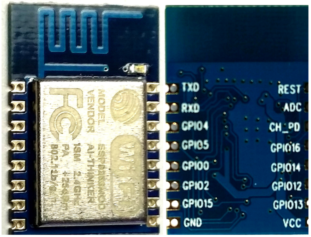
They are available in a 16-pin DIP package  with 2.54 pitch for easy use with a solder-less breadboard.muxpic
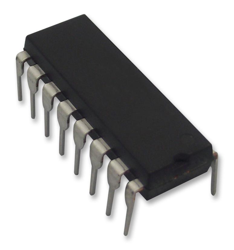
So what’s the downside? Well, selecting one of the 8 analog inputs will require 3 GPIO pins. For many applications, that should not pose a problem when using the ESP8266-07 or -12. These versions have 7 easily accessible GPIO pins available, leaving you with 4 GPIO pins for any digital input or output requirement after adding the 8 analog inputs.

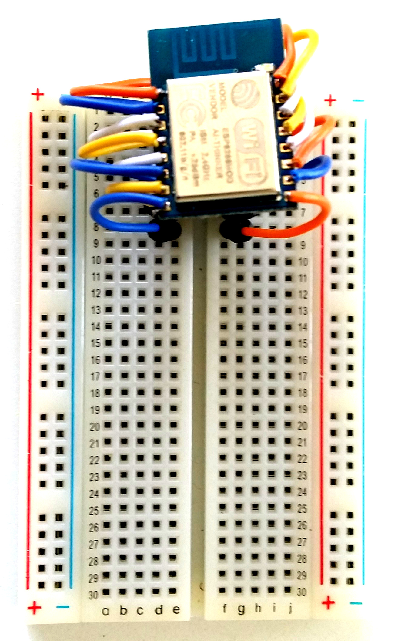
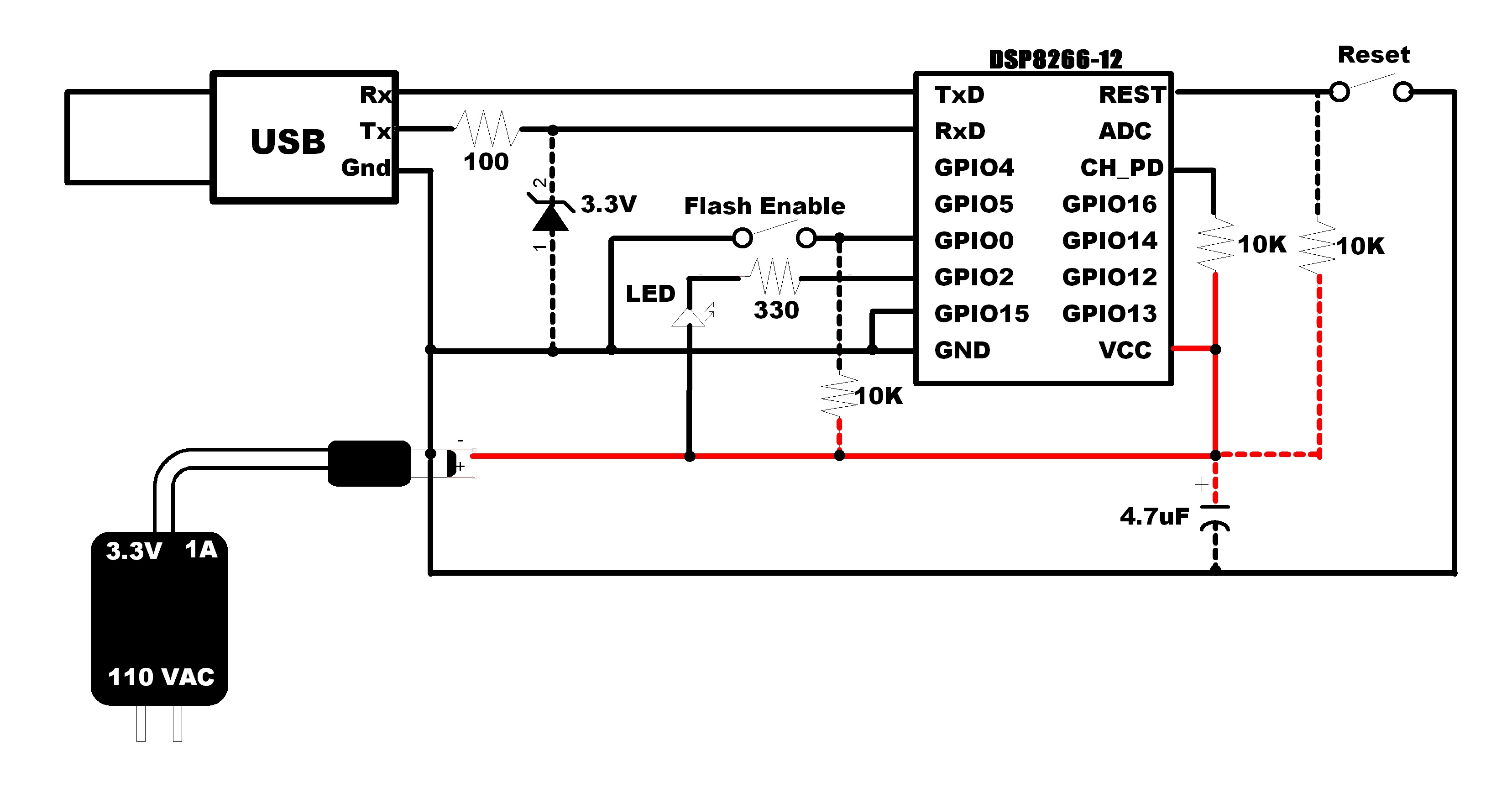
Here is the circuit I used to test this configuration:

ESP8266-schematic - amux-test_rev1

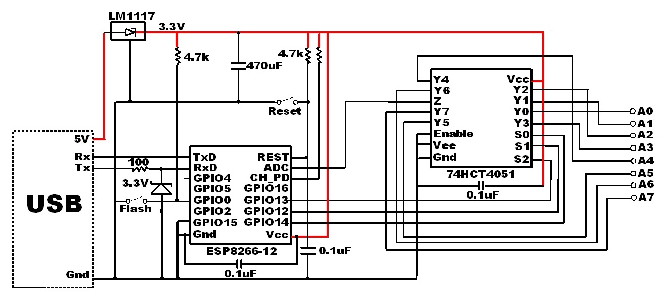
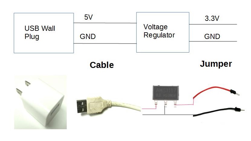
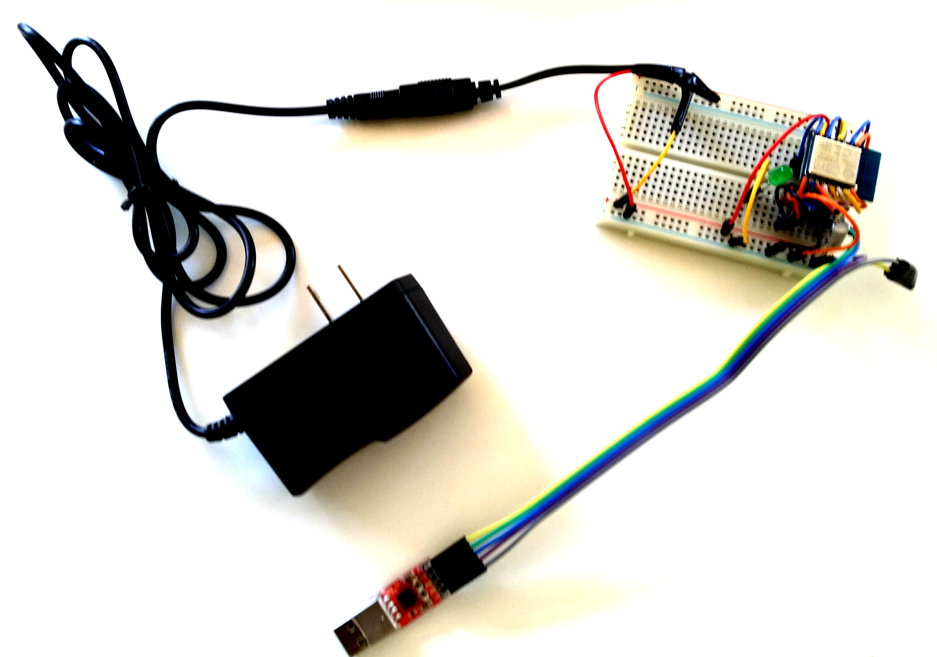
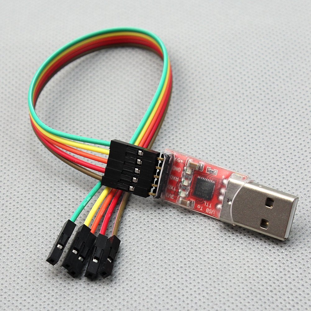
The left side of this drawing is the standard circuit I have been using for all of my ESP8266 projects. A typical USB to serial adapter is used when developing and flashing the circuit. When deployed, I use a USB plug with a wall adapter to provide a 5V source, without the Tx/Rx signals.

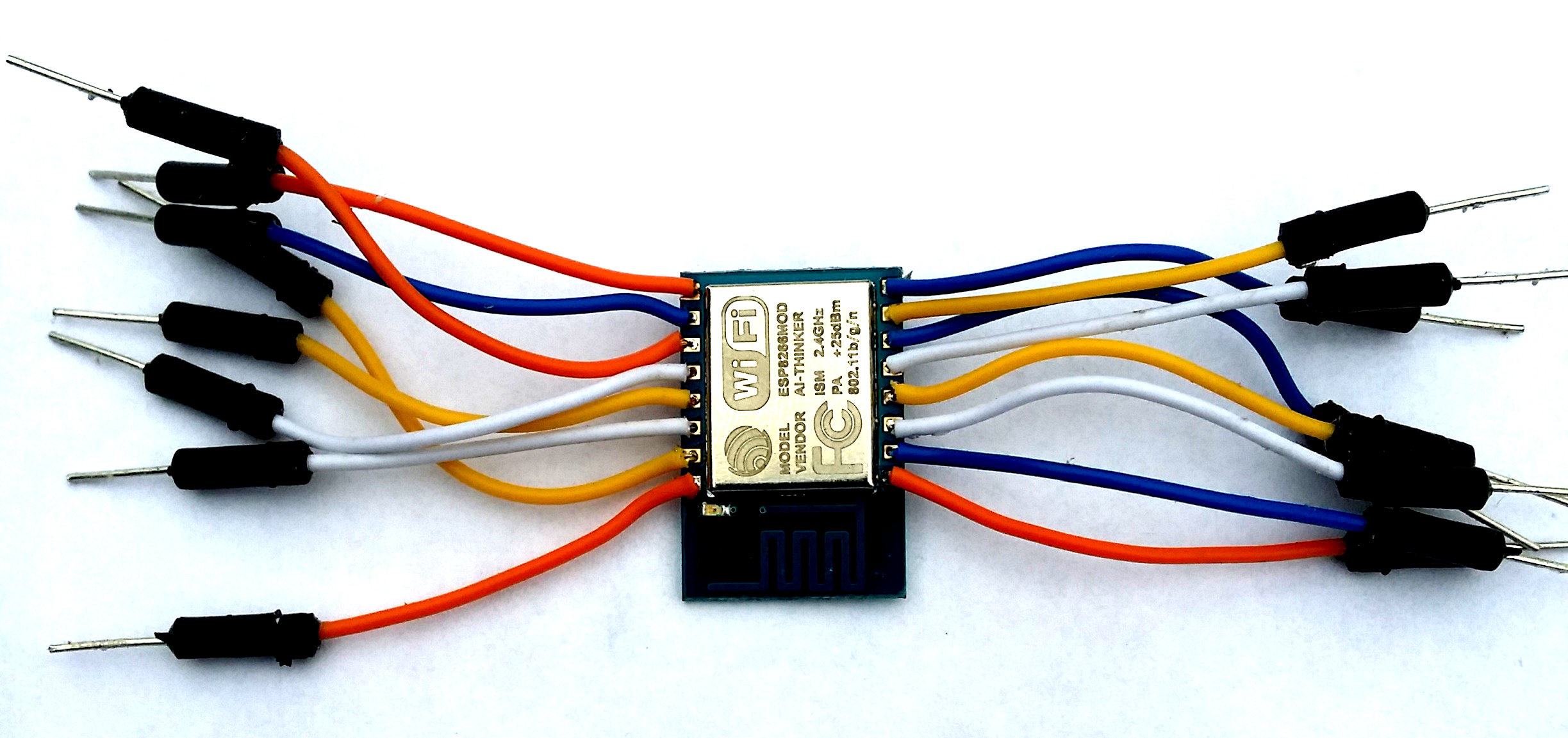
The analog multiplexer is controlled by 3 GPIO pins; 14,12 and 13. Setting the states of these 3 digital outputs determine which analog input will be measured.

GPIO14 GPIO12 GPIO13
A0 0 0 0
A1 0 0 1
A2 0 1 0
A3 0 1 1
A4 1 0 0
A5 1 0 1
A6 1 1 0
A7 1 1 1

The sketch used to test this circuit was developed using the ESP8266 Arduino IDE.

The serial output loops through each analog input, setting the multiplexer and reading an input every 2.5 seconds. The sketch also behaves as a web server. All 8 analog values can be retrieved in a single JSON string returned from an http GET request.

ESP8266 ADC Performance Evaluation

Using this circuit and software, I proceeded to collect some data to characterize the ESP8266 analog input range. First, the multiplexer selector was verified by connecting each input to ground and verifying the Analog count returned was 0. Likewise, each input was connected to 3.3V with a reading of 1024 returned when reading the ESP8266 ADC pin.

All good so far…

Then I connected the A0 input to a variable resistor to vary the input voltage voltage.

ESP8266-schematic - amux-Test-Circuit-updated

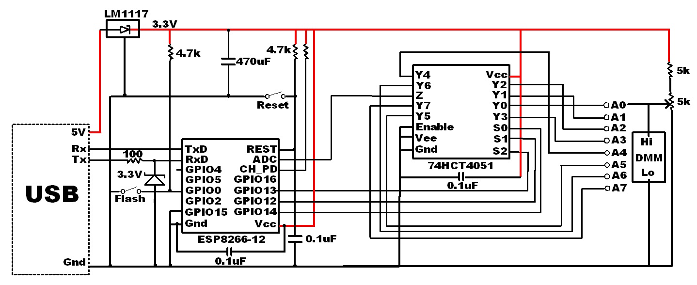
At the same time, an external Digital Multimeter (DMM) was used to monitor the voltage applied to the ESP ADC input via the multiplexer. For each voltage setting, I recorded the DMM reading and the ADC count returned from the ESP8266. It would have been great to have a calibrated bus controlled DMM to automate this process, but for the purpose of this DIY home project, I simply entered the values into an excel spreadsheet manually.

Thirty-seven voltage settings were applied in the range between 0.2V and 1.2V. Any voltage below 0.2V returned a 0 bit count while voltages above 1.2V returned 1024. I observed approximately 10 values returned from the ESP8266 for each voltage applied and recorded the high and low bit count readings for these measurements. The average of the high and low reading was then used to chart the results.

ESP8266 ADC voltage vs bit count

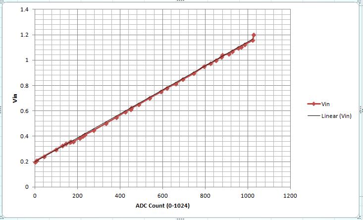
As you can see, the results were reasonably linear. But there is compression at the voltage extremes. For practical use, I would not use the non-linear ends, limiting the voltage swing from 0.25 to 1.15 V, a 0.9 V range.

The data collected can be reduced to a “best fit” equation. This would provide a method of converting the raw ADC value count to a voltage. Ideally, a data point should be collected for each ADC count value. The equipment I used for this exercise was not calibrated or accurate enough to do this. Given these uncertainties in my test setup, I am not sure if the variances I observed for consecutive readings…and they did vary somewhat…was result of the input voltage source or the ESP8266 ADC.

Still…with the data I had collected, the formula was determined to be:

Vain = (0.94* ADCcount + 200) mV

The slope was determined by dividing the voltage difference by the ADC count  difference at each end of the voltage range. And 200 mV, the intercept, is the voltage when the ADC started reporting 0 for the count.

While there does not appear to be a definitive specification, this is consistent with what I have read regarding the ESP8266. The 10-bit ADC resolution is supposed to be approximately 1 mV with a 1 V range.

Resolving Sensor Incompatibilities

So what can you do if your sensor range is outside the ESP8266 0.2 to 1.2 V window?

Scaling of course.

This can be accomplished passively, using a resistor divider, or actively, with the addition of an op-amp. The interface of choice would be an active op-amp based circuit.

For example, suppose your sensor has a 0-5V range. This would need to be scaled to fit in the ESP8266 0.2 to 1.2 V input range. Obviously, resolution will be compromised as we go from a larger range to a smaller one, but it can be done. And with a single power supply.

ESP8266 Analog Input Voltage Level Shifter

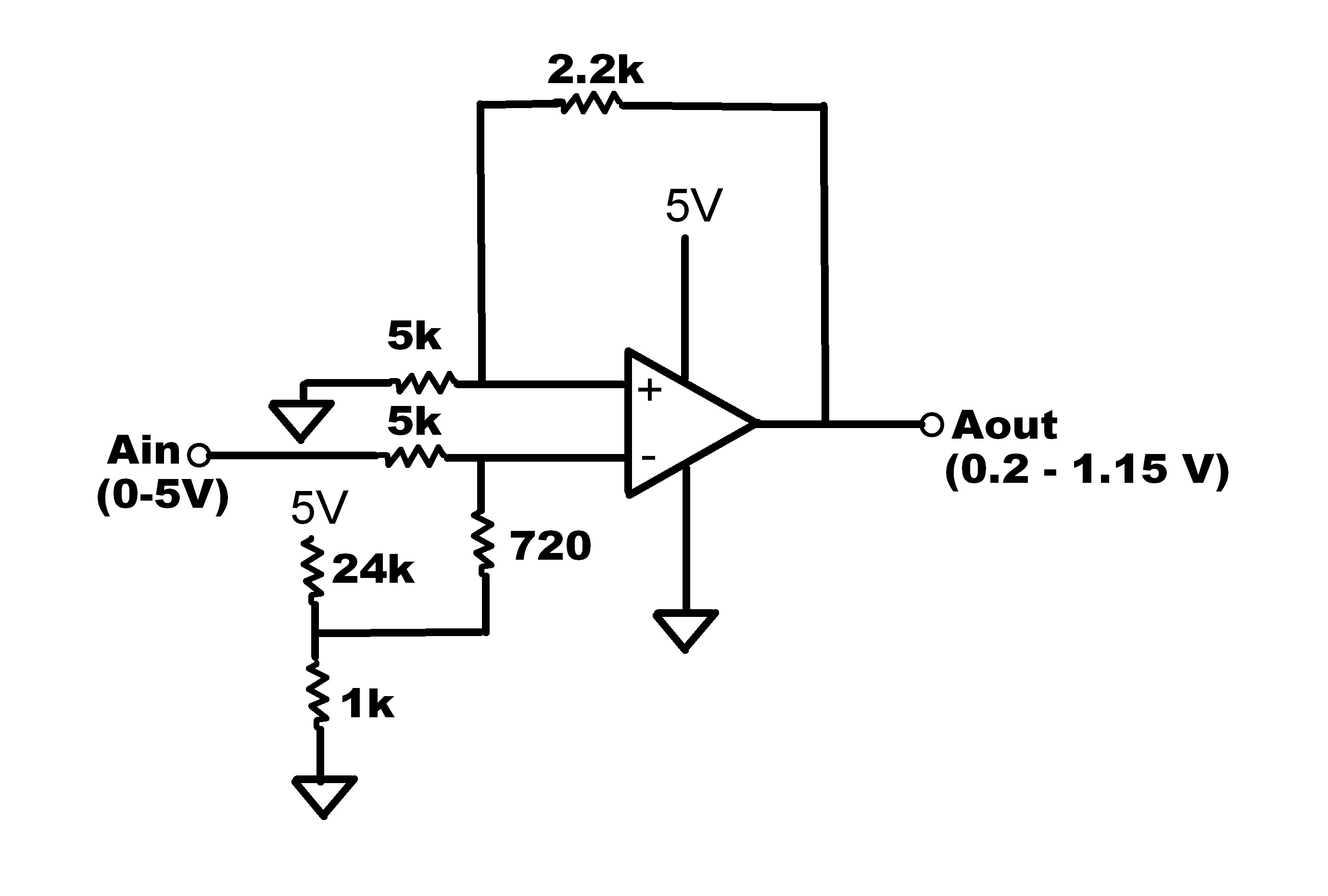
Resistor values calculated here. The 24K/1K resistor divider supplies the 0.2V offset with the gain set for the 1.15 V output with a 5V maximum input applied. This circuit would need to be modified for your specific sensor voltage range.

In summary

So there you have it. Eight analog inputs measured using a single ESP8266 SoC. Possible simply by adding a 22 cent chip.

And I got to mention one more option. Just in case you want even more…

A 16 channel version of the multiplexer is also available (74HCT4067). That’s a whole lot of analog!

I hope you find this information useful.

Loading

Share This:
FacebooktwitterredditpinterestlinkedintumblrFacebooktwitterredditpinterestlinkedintumblr

My ESP8266 Controlled Temperature Sensors now on ThingSpeak

Now that my ESP8266 controlled sensors have been on-line and are now reliably running, the next step was to push some of the data up to ThingSpeak. Up to now, I had been saving the readings exclusively in my host server account’s mySQL database.

And now the temperature readings are also pushed up to ThingSpeak, once every hour.

But not by the ESP8266 micro-controller. No…I have discovered that the stability of the ESP8266, at least at this time, is linked to the frequency of accessing it through http client GET requests. Access to my ESP8266 is tightly controlled. It has to be. I’ve written about structuring a stable ESP8266 Arduino IDE sketch loop() in another post. This may be helpful if you are have issues with the ESP8266 reliability.

The video created to describe the ThinkSpeak channel breaks down the unique methodology I’ve used to move sensor readings up to ThingSpeak.

You can check out the real-time data now visually served to the world on my new ThingSpeak channel. I’m hoping there is something unique about the method used to upload the readings and the eye-catching displays that could be of value to someone. Something not found on any other of the many channels displaying similar data.

Setting up the channel was easy. ThingSpeak is a free platform serving first as a repository database, like mySQL, to store data read from your Internet of Things (IoT) gadgets.

Once you have a periodic data feed to ThingSpeak, the platform can execute actions based on the data. It also provides a simple API to take some of the burden off your micro-controller. Here’s highlights of what ThingSpeak can do for you:

  • ThingTweet – This service provides a simple API for your IoT thing to post Twitter messages.
  • React -Performs whatever action you need when the data in your channel meets your custom set condition. Some obvious examples:
    • Turn light on when proximity sensor detects someone in room
    • Water lawn when moisture detector reaches dry threshold.
    • Turn heater on when temperature drops below certain reading.
  • TalkBack – API that has device execute queued commands. The queue is loaded in ThingSpeak. Then the device request a command, and performs an action based on the command it gets from the ThingSpeak queue. I have not thought of an application for this yet, but I’m sure you might find some from ThingSpeak.
  • TimeControl – Allows you to setup ThingHTTP or ThingTweet requests a a predetermined time. There are many ways to do this, but using ThingSpeak could reduce the burden placed on your device or other element in your IoT ecosystem.

Temp Humidity Baro-Pressure

That’s it for now. Keep your creative juices flowing. I may add my humidity and barometric pressure readings to the initial ThingSpeak soon – in a 3-gauge display window. Like you see above. Being in the US, my temperature is in Fahrenheit and the pressure is inches of mercury. What will you do next?

I hope you find this information useful…


Loading

Share This:
FacebooktwitterredditpinterestlinkedintumblrFacebooktwitterredditpinterestlinkedintumblr

Getting Started with the ESP8266-12

I was really excited when first discovering the ESP8266. Imagine…a tiny footprint device capable of connecting to the internet with a WIFI connection. With the capability to control ‘things’ and monitor sensors. A genuine SoC (System on a Chip). And best of all…for a price under 5 USD.

I was determined to make this as low cost as possible. So I found an inexpensive Asian supplier and ordered a lot of 5 of them for $2.68 each. And FREE shipping.

But I knew the delivery would be slow with these terms so I researched what else was needed. A USB to serial converter was the only other thing essential to getting started. This would be used both for programming the ESP8266 and providing it with the required 3.3V power source. Another search netted a supplier of these at $0.64 each (minimum order of 10).

Hmmm…if this works, throw in a couple of sensors and stuff and we what we have is still a very low-cost solution to internet-enable something—perhaps EVERYTHING!

It did take a while for those ESP8266 devices to arrive…46 days from the order date. But hey, with all my other “irons in the fire”, this was not even an inconvenience.

So when the hardware arrived, I started to search for a simple way to get started. What I found was that there are many variants of the ESP8266, and they do not all behave exactly the same. I had ordered the ESP8266-12 models. These were 16-pin devices and all the information I found was for the earlier designs, the 8-pin variety. And yes, there is an important set-up for the ESP8266-12 that was not mentioned for the earlier units.

The purpose of this document is to provide a ‘getting started quickly’ guide for the ESP8266-12. What’s great is that almost all of the steps also apply to the earlier versions.

The ESP8266 is an open-source device with bits and pieces of the puzzle scattered about. Piecing it all together can be somewhat challenging. I hope the information presented here makes it possible for someone to get started quicker and easier than I did, without needed to jump elsewhere for missing pieces.

Getting started with the ESP8266 breaks down into five steps:

  1. Connecting the hardware

  2. Install the USB to serial device driver

  3. Verify the unit is functional

  4. Flashing NodeMcu

  5. Installing an application

Step 1: Connecting the hardware

This is a list of all the components I used to get started:

  • ESP8266 module
  • USB to Serial converter
  • 3.3V 1A Power Supply
  • Capacitor (4.7uf)
  • LED
  • Resistors (10 kohm (3), 330 ohm, 100 ohm)
  • Zener Diode (3.3V)
  • Breadboard
  • Jumper wires

ESP8266 in ESD bag


The ESP8266-12 units were delivered in sealed ESD bags. No headers were installed on the printed wiring board. But a bigger issue was that the centers between each pin (8 on each side) are 2mm. That is tighter than the 2.54 mm of a standard breadboard.

ESP8266-12 Top and Bottom Views

ESP8266-12 Top and Bottom Views


First challenge was to make the module mountable on a breadboard. Anxious to get started, I took the quick and dirty route and simply cut 8 breadboard jumpers in half, enough for 16 signals. The cut end was stripped and soldered to the ESP8266-12, one wire on each of the 16 holes. This got me started quickly without needing anything extra, like a separate perforated board to break-out the signals. Not pretty, but it’s working just fine for initial prototyping.

ESP8266-jumpers

The “jumper-ed” module mated easily to a breadboard.

I would have used shorter jumpers if I had make this setup again. With tighter connections, the jumper pins would have connected to the breadboard somewhat cleaner; almost straight down from the module. But then, this is just a quick-start setup and has proven to be quite reliable.

ESP8266-OnBreadboard

As an initial test, a simple flashing LED will be coded. As shown below, the hardware needed for this is minimal. Note that GPIO15 must be grounded. That fact was not stated in much the information available on-line regarding this module. The unit will simply not work without this connection. I hope this saves someone from the initial grief I went through prior to properly configuring GPIO15.

schematicNEW

A few notes regarding the circuit:

  • Components connected with ‘dashed’ line are optional but recommended for reliable operation.

  • Connecting GPIO0 to ground should only be made when flashing the ESP8266. It is shown with a switch in the path, but simply adding this connection as a breadboard jumper when flashing is adequate.

  • During development and testing, there will be times when you will ant to reset the module. This can be done by momentarily connection a jumper from REST to ground.

  • The 100 ohm resistor and 3.3V zener diode from the USB transmit signal to the ESP8266 receive protects the ESP8266 from potential damage from exposure to 5V. The module is not specified to accept any inputs greater than 3.3V.

  • It is a good practice to have a capacitor across the power rails near the active components. The 4.7 uF capacitor I used is larger than what is needed for this simple circuit. I suggest using one greater than 0.1 uF.

  • A separate 3.3V power source is needed. Do not use the USB 3.3V output.

To be honest, my initial set-up did not even include the external power supply. I was using the 3.3V provided by the USB to serial bridge (top contact of red device above). But the performance was intermittent. Sometimes it would fail during a flash, and the unit would often freeze it’s activity after a short time running. These problems were eliminated after using an external supply to power the ESP8266.

The problem is that the USB bridge’s 3.3V output provides insufficient power. The current tops out at 100 ma while the ESP8266 can require more than 200 ma. I recommend that you save yourself some headaches; USE A SEPARATE 3.3V POWER SUPPLY.

Slow boat from China

Another power supply option: Almost everyone has a few 5V USB wall plus for various uses. And who doesn’t also have one or more USB cables that no longer charge properly? These cables, along with a cheap 3.3V voltage regulator offer an inexpensive way to satisfy the ESP8266 power requirements. I have found a supplier selling regulators, model LM1117, for 0.04 USD each, but you have to order a minimum of 100, a lifetime supply for 4 USD…and this includes free shipping). Only catch is that it will take about 45 days to receive the goods on that slow boat from China).

5V_3.3V

Here is what my test setup looked like after all the jumpers were in place:

ESP8266-TestSetup

Step 2: Install the USB to serial device driver

If you have already have a working serial interface, you can skip this section and move on to step 3.

There are many USB to serial devices available that will work well to program the ESP8266. If you do not have one already, you simply need a serial port with 3 signals:

  • Transmit

  • Receive

  • Ground

The one I selected provided 3.3V output. At the time, I thought this was essential, thinking that it would be needed to drive the ESP8266. But now, using an external supply for the 3.3V source, this voltage out of the USB to serial module is not necessary and is not used.

Just follow the instructions for your serial port to install the drivers. Installation for my device, which is based on a CP210x chip, is provided in a separate post.

Step 3: Verify the unit is functional

We now have the hardware setup established. Let’s make this thing work. Here is where things start to get interesting.

First, connect the USB to serial device to your computer and plug in the power supply. If the ESP8266-12 is functional, you should see the blue led flash twice when the power is applied. Great, this is the first confirmation that the unit is alive.

What is needed now is a method to verify the unit is functional, the ability to develop code and to flash the unit with code. Here we go…

First, open up your favorite terminal program such as putty or tera-term.

Start-up by applying power to the unit, or connect and release a jumper from REST to ground with a powered up unit.

Expect the blue led to flash twice on start-up.

Note that start-up output at the terminal windows is garbage at both 9600 and 115200 baud. I tried this at all baud rates from 110 to 921600…none of these rates resulted in a recognizable output.

initialserialoutput

This suggests that the unit is not shipped with firmware. To get started then, you will need to get the AT command set firmware and flasher. There are many sites that have it. I got my copy here.

Knowing that things change over time, it is suggested that you do a search for “ESP8266 flasher” if it is no longer at the site mentioned.

Flashing the AT command firmware

Now let’s flash some firmware:

  • Ground GPIO0 and start-up or reset device.

    • You should see the blue LED flash once.

  • Run the executable “esp8266_flasher.exe” that was just downloaded.

  • Click the “Bin” button to select the downloaded firmware (ESP_8266_BIN0.22.bin).

  • Enter the COMx number assigned to your serial port (mine was 7).

  • Click “download.

ESP8266Flasher

When the download finishes, you will see “Failed to leave Flash mode”

Ignore this and close the downloader program.

Remove the GPIO0 to ground connection.

Reset the ESP8266: You will see two blue flashes again (the second flash is dimmer than the first).

The firmware is running at 115200 now and should respond to AT commands.

The most basic command to verify the firmware:

Enter “AT<enter>”

ESP8266 response: OK

The complete AT command set can be found here.

If you plan to use the ESP8266 as a slave to an Arduino or other MCU, you are ready to go.

But if you are planning to use the ESP8266 as a stand-alone prototyping platform, read on…

Step 4: Flashing NodeMcu

NodeMcu is open-source firmware for the ESP8266 which makes it easy to prototype “things”. It is similar to the Arduino development environment.

More information is available here.

Let’s set up the ESP8266 for NodeMcu.

First, pull the Flasher and firmware from GitHub:

Click on the “Download ZIP” file to get the entire package.

I used the 64-bit version for my windows 7 PC. It was in the repository at:

nodemcu-flasher-master\Win64\Release\ESP8266Flasher.exe

Before starting this program, make sure the GPIO0 is connected to ground. Then start the flasher program which should start up with:

ESP8266 Flasher NodeMcu

The COM Port should be the same one you have been using to communicate with the ESP8266.

Click on the “Flash(F)” button to flash NodeMcu on your device. This will take a few minutes. You will see the progress bar fill and the ESP8266 blue LED blink during the flashing. A green Check will be displayed when the flash is completed.

After Flashing ESP8266 with NodeMcu

Once the flash is complete, you can remove the GPIO0 to ground jumper. It will no longer be needed. All that you will need now to develop your own applications is an integrated development environment (IDE).

ESPlorer appears to be the most widely used ESP8266 IDE. Get it now here.

Simply run the batch file “ESPlorer.bat” to start the IDE. A command window will be launched along with the IDE GUI. DO NOT close the command window!

ESPlorer IDE

The ESP8266 starts up now with it’s serial port set to 9600 baud. In order to start the communication link, you will need to click on the “Open” button (COM port set to the number corresponding to the ESP8266 to PC serial bus).

If the port opens successfully, the IDE window will look like this:

ESPlorer2

Now click on the “ResetESP” button. The ESP8266 should respond with the firmware version:

node.restart()

> #ü!##¤„ÿ1ä)Mô1ä)}†1¤ñ¡Hø

NodeMCU 0.9.5 build 20150311 powered by Lua 5.1.4

>

Congratulations! Your ESP8266 development environment is now set up.

Step 5: Installing an application

It is time to write and flash our first program.

Lets try writing a simple program to blink an LED on and off. It is structure here to appear similar to the familiar Arduino structure. The code is entered in the window with the “Scripts” tab selected:

ESPlorer3

Notice the file is assigned the name “init.lua”. This is the default file that is run on the ESP8266 at start-up. This program simply toggles the LED state every 1 second. The GPIO2 is assigned an index 4, which is why this value is used in our script to control the connected LED.  Look here for the remaining GPIO to index mapping. Simply click on the “Save to ESP” button to flash the code to the ESP8266. The LED should then change state every 1 second.

Also note the ‘dofile(“init.lua”)’ in the right window. The IDE commands the ESP8266 to start this script after flashing with this command.

NOTE: While it may change in the future, currently, the IDE does not provide a means to create new files to your PC. The file “init.lua” must be created with an external text editor before it can be opened in the IDE.

This is just the beginning… A starting point so you can begin exploring what is possible with this remarkable device. I have already made a simple server to control an LED from a web-page and return a JSON string. I’ll leave that as an exercise for you and perhaps provide the details in another post.

The complete API and GPIO index mapping is maintained here.

And there are examples of different code snippets, including configuring the ESP8266 WIFI for internet here.

I’ll be back with more as I get more experience with this device.

My next step is to port the code I have currently deployed to a Spark Core (running continuously for almost a year now) to the ESP8266-12 platform to compare performance.

What will you do next?

Loading

Share This:
FacebooktwitterredditpinterestlinkedintumblrFacebooktwitterredditpinterestlinkedintumblr

ESP8266 Power and Serial Interface

So now you’ve gotten your hands on an ultra low-cost ESP8266 module.

Your ready to get started…

But what else do you need?

The only other hardware you need now to make this thing functional is an interface for development. This interface must support firmware flashing and testing. It must also provide a power source. Fortunately, there are several low-cost options available to satisfy these basic needs.

What you need is a USB to serial converter. Of the models available…and there are several unique ones available, it is essential that you choose one that provides a 3.3V output required by the ESP8266. This output is not present on all converters so you must make sure you select one that does. The standard 5Vdc USB output is too high for the chip, and will most likely destroy it. And nobody wants another brick in the stash of gadgets!

From a brief search on Amazon, I found a device that met the requirements. My device uses a CP210x chip-set. While I could have purchased a cheaper unit from an Asian supplier, this was still a decent value at less than 4 USD and with fast-free shipping, I got the device in days instead of months.

Making prototyping a snap, a 5 pin ribbon cable is included with female contacts that can be attached directly to male breadboard jumpers.

ESP8266 Power and Serial Interface

From this USB plug-in module, 5 signals are provided:

      • 5 Vdc
      • 3.3 Vdc
      • Ground
      • Serial Tx
      • Serial Rx

But remember, the 5Vdc output must not be used when interfacing with the ESP8266.

Since I am using a Windows 7 OS PC for development, a compatible driver was needed to make this device functional. For this device, the driver can be found at:
https://www.silabs.com/products/mcu/Pages/USBtoUARTBridgeVCPDrivers.aspx
There are drivers available there for Windows, Windows CE, Linux, and Macintosh.
Driver installation is straightforward. Simply download the files and follow the instructions from this website.


usb_driver


I used the Windows Device Manager to install the driver. There are several ways to pull up the Device Manager on a Windows PC. One simple method is to type “Device Manager” in the Start pop-up in the box with the placeholder “Search programs and file”:


Open Device Manager


With the USB device attached to the PC (with no driver installed), right-click on the device and select “Update Driver Software…”


DeviceManagerBefore


Then, select “Browse my computer for driver Locate and install driver software manually.”


UploadDriverSoftware1


Select the folder that the driver downloaded to on your computer:


UploadDriverSoftware2


Clicking “next” installs the driver…and that should do it:


Finished


When you click “close”, the driver should be installed and the device manager updated with the correct driver information, including the COMx assignment.

DeviceManagerAfter


If you want to customize the COMx port number assignment, right-click on the newly installed USB to UART bridge driver, select “Properties, the “Port Settings” tab and “Advanced…”


ComPortAssignment


Note that while the USB to serial device’s 3.3V output can be used to power the ESP8266 when programming the device, it is inadequate as a stand-alone power source. The maximum output is specified to be 100ma while the ESP8266, when transmitting, could require up to 215 ma. Even though the ESP8266 can be programmed for several lower power transmit modes, none falls below the 100ma maximum that the USB to serial device can deliver.

          • Transmit 802.11b, POUT=+19.5dBm 215 mA
          • Transmit 802.11b, POUT=+18.5dBm 197 mA
          • Transmit 802.11g, POUT=+16.0dBm 145 mA
          • Transmit 802.11n, POUT=+14.0dBm 135 mA

Thus, a separate 3.3V source is needed to power the ESP8266 for a fielded application What is important to keep in mind is that the ESP8266 needs a regulated 3.3V power source. I recommend using a single-chip regulator for this purpose.

One such device, which can be purchased fro about 1 USD on-line from Amazon or Adafruit, is the 3.3V 250MA LINEAR VOLTAGE REGULATOR (Part number L4931).

This unit will regulate any source (3.7 – 20 Vdc) down to a clean 3.3V, and providing up to 250 ma.

3.3V Voltage Regulator
With this simple circuit, you can use any commonly available USB source to power your ESP8266 based project. Just make sure the source is rated to supply the needed current. Power sources like a USB battery, car or wall adapter.

Until next time…

Loading

Share This:
FacebooktwitterredditpinterestlinkedintumblrFacebooktwitterredditpinterestlinkedintumblr