MQTT

MQTT Android Studio App


Creating a native MQTT App provides a convenient platform for complete customization of any IoT project. Yet the effort to develop a Android Studio App can seem daunting. With a huge learning curve just to accomplish the simplest of tasks.

To my surprise, however, I found it reasonably simple and easy to create a basic app framework upon which to expand into a full-blown tool for MQTT interactions.


For those that just cannot wait, here is the project. You can even install the apk file app-debug.apk on your Android device now.


Keeping things reasonably simple and easy, here is how I did it…

Installing Android Studio

This was as easy as a google search and file download. Use this link to install Android Studio on a PC with Windows 10 operating system.

Install Android Studio

Creating the Project

After installing and opening Android Studio, create a new project (File->New->New Project…

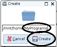
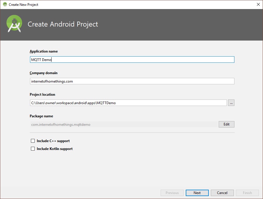
Enter a name for the project and click “Next”. The project location can be anywhere on your hard drive, ending with the folder name matching the project name:

These were the default settings used on the next screen:

Next, Select “Bottom Navigation Activity”.

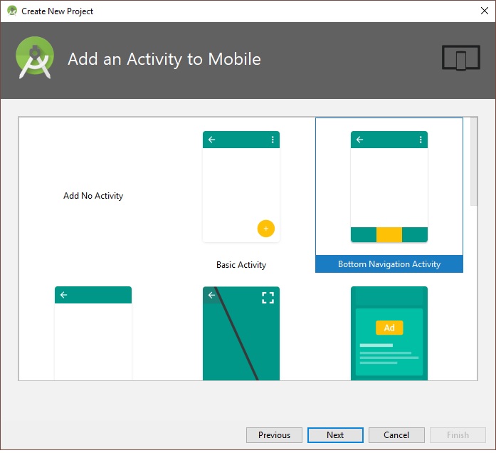
Use the default activity name:

Click “Finish” to complete the App framework creation.

The demo App will build.

Before we add the code for MQTT, it would be a good idea to build the apk and install the app on your android device to make sure the framework is functional.

Select Build-> Build APK(s) from the menu.


Click on “locate” to open the file manager with the location of the apk. You can transfer this file to your android device to test the app framework. The app should start to the following screen:

Now lets add the MQTT Demo code.

For this exercise, close Android Studio and simply replace the contents of the project folders with the files I have uploaded to Github here. Then we will walk through the code.

Copy <github/MQTTDemo> folder to <your project base directory>/MQTTDemo

The project files is partitioned into 3 main folders:

  1. <your project base directory>/MQTTDemo/app/build
  2. <your project base directory>/MQTTDemo/app/libs
  3. <your project base directory>/MQTTDemo/app/src

The build folder contains the output files from the build, libs contains the paho MQTT libraries, and src has the source code for the project. You can download the paho library files from here.

Now let’s open Android Studio to this project and review the source code:

The MQTT libraries as dependencies of your Android project

Open the build.gradle file. Here you will see the paho libraries added to file dependencies section:
dependencies {
    …    
    compile files(‘libs/org.eclipse.paho.android.service-1.1.1.jar’)
    compile files(‘libs/org.eclipse.paho.client.mqttv3-1.1.1.jar’)
}

Permissions and Service additions to the AndroidManifest.xml file

Open the app/AndroidManifest.xml file. Note the following permissions required by the app added to the manifest:
<usespermission android:name=“android.permission.INTERNET” />
<usespermission android:name=“android.permission.WAKE_LOCK” />
<usespermission android:name=“android.permission.ACCESS_NETWORK_STATE” />
<usespermission android:name=“android.permission.READ_PHONE_STATE” />
The Paho Android Service must also be added within the manifest <application> tag.

Customizing the App GUI (activity_main.xml file):

From Android Studio, the app opening GUI is layout is defined in the file app/res/layout/activity_main.xml

A preview of the GUI can be seen by selecting the “Design” tab while the xml code needed to generate the GUI can be edited from the “Text” tab.

While not necessary, inn order to make it easy to follow, the GUI components are listed in the xml file in the top-to-bottom order that they appear on the screen.

  • LinearLayout…requestFocus

Note that this object has a defined width and height of 0px, making it invisible. This object is used to set initial focus when the App is opened. Without this object, the app sets focus on the first editable field and the edit alphabet pop-up appears, somethings that is clearly undesirable on start-up.

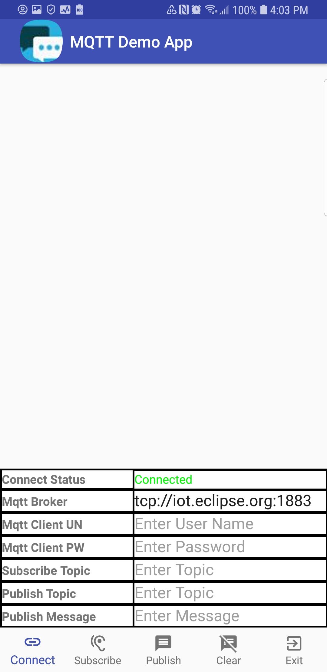
  • LinearLayout…ScrollView…TextView

This object is the large white space in the layout above. It displays MQTT messages as they are received.
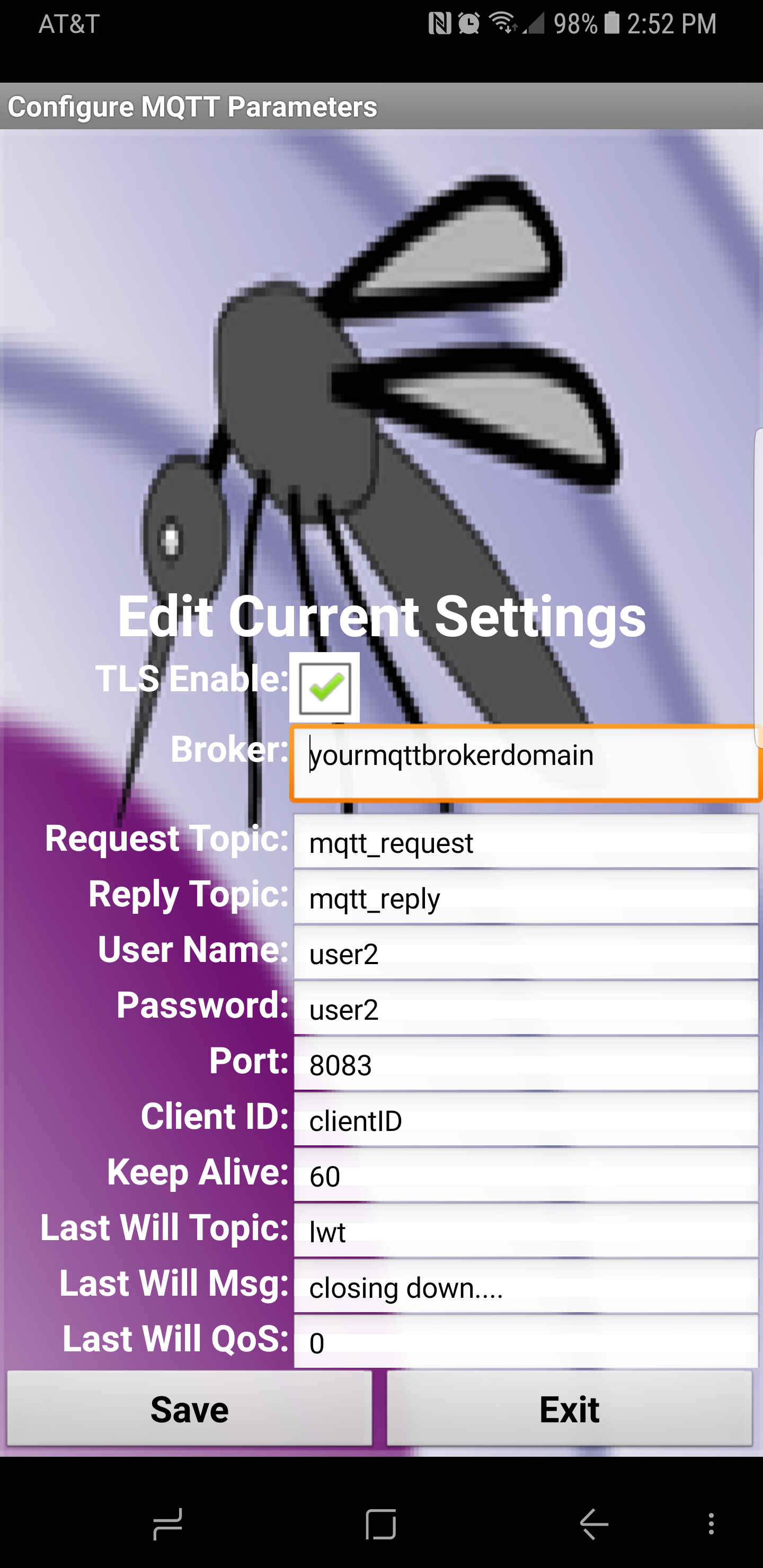
  • TableLayout

This object is the tabular information on the bottom half of the screen. This table is used to input MQTT connect parameters and to display the connect status.

  • BottomNavigationView

This object is the icons and text along the bottom of the screen. Upon tapping, these items trigger action by the app.

Bottom Navigation Menu (app/res/menu/navigation.xml file)

This file defines the five navigation items displayed along the bottom row of the screen. Three fields are needed for each item.

  1. id – identifies the item for access in the java code
  2. drawable = defines the item icon
  3. title – defines the text to be displayed under the item icon

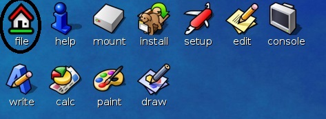
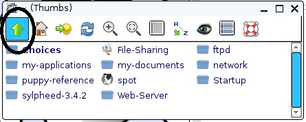
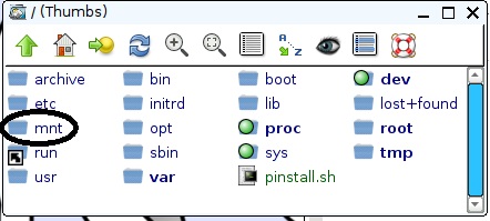
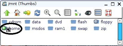
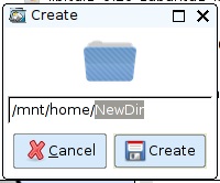
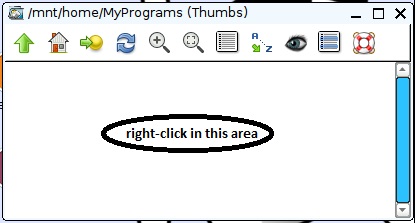
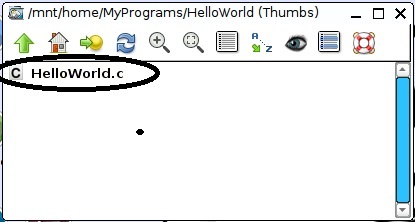
The icons can be selected from the Android Studio library or a custom icon can be used. To add an icon to the project, right click on the app->res->drawable folder selecting New->Drawable resource file:

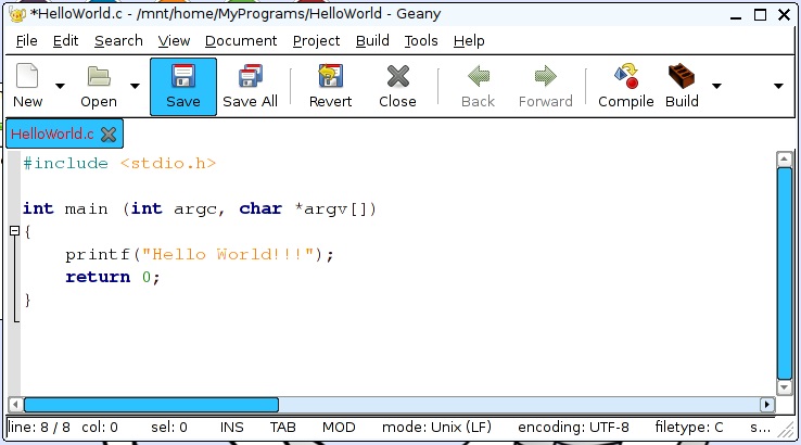
The java code (app/java/<project package name>/MainActivity.java)

The startup and callback code is contained in the MainActivity.java file. A separate file is needed for each app scree. Since this demo app only uses 1 screen, only 1 file is needed.

The App code (class Methods) are contained within the MainActivity class.

This apps simple method simple structure:

  1. onCreate – Executed upon App start-up
  2. <strong>RunScheduledTasks</strong> - Runs scheduled tasks once every second
  3. <strong>OnNavigationItemSelectedListener</strong> - Callback executed when a bottom navigation item is tapped.
  4. <strong>mqttCallback</strong> - Callback executed whenever a subscribed MQTT message is received

How it Works

When the app is started, GUI is rendered and onCreate is executed. Here is the sequence performed in onCreate:

  1. GUI layout is associated with the Apps opening activity
  2. A custom icon is added to the app’s title bar (you can change this, of course)
  3. A vertical scroller is added to the message window
  4. A client connection to the MQTT broker defined by the GUI table is made
  5. The bottom Navigation menu callback is registered.
  6. The text under each Navigation icon is made visible
  7. The callback for MQTT messages is registered
  8. The 1 second scheduled tasks callback is registered

After startup, the 3 app callback are active, waiting for a trigger to initiate execution

1. Scheduled tasks (runs once per second)

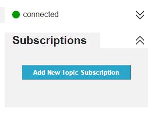
This App only requires one scheduled task. The app checks to see if the MQTT client is still connected to the broker. If connected, the display says “Connected” in green text. If the connection is lost, it displays “Disconnected” in red text.

2. Navigation Callback

The callback determines which item was tapped and then performs the applicable action:

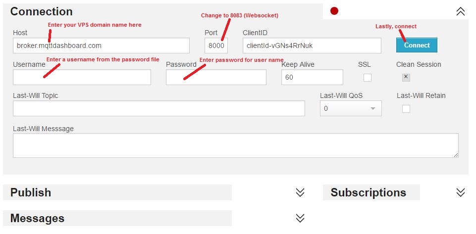
Button 1: Connect – If connected to the broker, the connection is closed and then reconnected using the parameters currently displayed in the table. You can change the broker url prior to tapping this button to connect to a different broker, The table also has field for username/password if the broker supports and requires those fields. Using the paho library, two connection types are supported: tcp and ssl. An example of the broker url format for these connections:

tcp://&lt;broker domain&gt;:1883
ssl://&lt;broker domain&gt;:8883

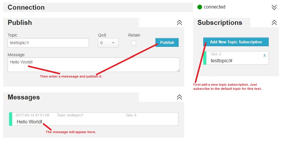
Button 2: Subscribe – If connected to the broker, a subscription to the topic entered in the table is made. But if not connected, a message is displayed indicating a subscription cannot be added unless connected to the broker.

Button 3: Publish – If connected to the broker, the message entered is published to the topic entered in the table. But if not connected, a message is displayed indicating a message cannot be published unless connected to the broker.

Button 4: Clear – Erases the content of the message window.

Button 5: Exit – Exits the App.

3. Subscribed Topic Callback

The code executed when a subscribed message is receive is structured as if/then conditional statements. Once condition is executed for each unique topic executed. This provides a mechanism to execute topic specific code.

But in this demo App, the specified unique topics are not used. In that condition, the default “else” case is executed, which simply echos the published message in the message window.

In Closing

With the App framework presented, a full-featured app can be developed to interface with an MQTT broker to monitor and control your IoT devices. It can also be used as a client to test out MQTT clients connected to a common broker. Once again, the project can be downloaded from Github here.

Hope you find this project useful.

Loading

Share This:
FacebooktwitterredditpinterestlinkedintumblrFacebooktwitterredditpinterestlinkedintumblr

MQTT for App Inventor – Adding TLS Security

This article adds TLS security as a connection option to my original MQTT App Inventor project. The addition is relatively straight-forward.  The App already had the ability to configure MQTT connection and message parameters. Adding the TLS option was a simple matter of adding a check-box to the configuration screen and modifying the JavaScript code used to communicate with MQTT.

Here are a few of my past posts for review. They are related to MQTT and TLS connections:

Now lets update the App Inventor project to support TLS connections to an MQTT broker. Since this article only covers the updates needed to support TLS, it is recommended that the initial project article be reviewed in case anything is unclear.

And if you want to jump ahead and have a look at the project, here it is.

Updating the Configuration GUI

Since the choice is binary, that is, we either want to connect using a TLS or a non-TLS MQTT channel, the GUI selection is obvious; a checkbox. This was added to the top of the configuration screen. You can customize the position if desired.

Updating the Configuration File

We use the same configuration file as the original project. Each configuration parameters is stored in this file as a JSON string. The file resides on our target Android device. The checked/unchecked state of our added checkbox gets saves in the JSON object as a “true” or “false” string.

The TLS connection option is added at the bottom of the configuration file (cfg.txt).


  1. {
  2. "mqtt_broker":"yourmqttbrokerdomain",
  3. "mqtt_txtopic":"mqtt_request",
  4. "mqtt_rxtopic":"mqtt_reply",
  5. "mqtt_un":"user2",
  6. "mqtt_pw":"user2",
  7. "mqtt_port":"8083",
  8. "mqtt_clientId":"clientID",
  9. "mqtt_keepalive":"60",
  10. "mqtt_lastWillTopic":"lwt",
  11. "mqtt_lastWillMessage":"closing down....",
  12. "mqtt_lastWillQoS":"0"",
  13. "mqtt_TLS_enable":"true"
  14. }

Updating the JavaScript

The JavaScript used to interface with the MQTT broker is the final but most important element of this update. Just as in the original App, the JSON  string containing the MQTT connection parameters is sent to the JavaScript using the App Inventor “WebViewString” feature.

Just as before, our custom JavaScript behaves as a “Wrapper” server, which communicates with the open-source MQTT 3.1.1 WebSocket API (mqttws31.js). Again, if this is unclear, please review my original project description.

The custom JavaScript code is stored in the file “mqtt_appinventor_paho.html”. Adding the TLS connection option required only one new line of code:


  1.   connectOptions.useSSL = cfgpar.mqtt_TLS_enable == "true";

That is the power of JSON.

The configuration file received via “WebViewString” from the App Inventor App can be parsed by parameter name (cfgpar.mqtt_TLS_enable). If the string is set to “true”, the connect option “useSSL” is enabled. If the string is not set to “true”, then the “useSSL” option is disabled. connectOption.useSSL is built into the open-source MQTT Websocket API.

That’s it!

The updated App Inventor project is accessible on GitHub here.

Testing the Update

When testing this update, it is important to remember to configure the MQTT port to one that is known to support TLS connections.Since this App is designed to communicate with an ESP8266 via an MQTT broker, it is recommended to test the App using the ESP8266 and MQTT broker from these posts:

But if you simply wish to verify the MQTT connection, any MQTT client can be used. My favorite is the web-based HiveMQTT client.

In Closing

There  you have it. Secure TLS MQTT connections in an App Inventor project. Hope you find this feature useful.

Loading

Share This:
FacebooktwitterredditpinterestlinkedintumblrFacebooktwitterredditpinterestlinkedintumblr

ESP8266 SSL/TLS MQTT Connection

Securing your IoT things is critical. MQTT connections are definitely at risk. But simply using username/password combinations for your MQTT connection is NOT secure.

Why not?

Well, even with passwords, everything sent over the Internet is unencrypted…open for any and all prying eyes to see…and possible maliciously manipulate.

Fortunately, we can solve that problem by creating TLS connections for secure MQTT data transfers. And yes, this encryption layer can even be brought to the ESP8266 platform.

But it does come at a cost…a huge bite out  of the limited ESP RAM heap. With grave consequences. I certainly experienced catastrophic results during in my initial attempts. Finally, and after several iterations, the implementation presented here now manages the heap successfully. Using this approach, we achieve the desired results…a  stable, reset-free ESP8266 platform with a secure interface to an MQTT broker.

Cutting to the Chase

At this point, if you would like to jump in without the benefit of additional explanation, please find the code for this Arduino 1.8.2 IDE compiled project here.

Compiler Issue

The first step towards adding TLS to the ESP8266 framework was to access a secure MQTT Broker. Installation of a TLS MQTT Broker was presented in my last post. After setting up the TLS MQTT broker on a VPS host, the next step was to update the ESP8266 IoT platform developed previously to support the secure connection. This required the addition of a new class to the project; WiFiClientSecure. This class supports secure TCP connections.

But I soon discovered the first problem…

You see, the project simply would not compile with the introduction of this class.

Through much research and frustration, I finally discovered the root cause of the problem and better yet, a solution.

As it turned out, one of the compiler flags used by the Arduino IDE was incompatible with the new WiFiClientSecure class library, and had to be   revised. While your computer may have a different path to the compiler options file, mine was located on a Windows 10 PC at:

C:\Users\owner\AppData\Local\Arduino15\packages\esp8266\hardware\esp8266\2.2.0\platform.txt

Here is the line that needs to be changed in order to compile the project:


  1. #OLD: compiler.c.elf.libs=-lm -lgcc -lhal -lphy -lpp -lnet80211 -llwip -lwpa -lcrypto -lmain -lwps -lsmartconfig -lmesh <span style="color: #ff0000;">-lssl</span>
  2. #NEW: compiler.c.elf.libs=-lm -lgcc -lhal -lphy -lpp -lnet80211 -llwip -lwpa -lcrypto -lmain -lwps -lsmartconfig -lmesh <span style="color: #ff0000;">-laxtls</span>

A Heap of Trouble

After a successful compilation and upload to my development ESP8266 hardware, I soon discovered that the TLS connection consumed a huge chunk of the ESP heap (RAM). Somewhere between 12 and 15 kB. This was such a big resource hog that the ESP8266 would reset anytime a TLS MQTT connection was attempted.

And I also discovered that the configuration screen also used a large amount of ESP heap. That was because, even though the page’s HTML was stored in program memory as a constant, it had to be brought into the heap for run-time modifications before the page was rendered.

These two processes, ESP configuration and TLS MQTT connection negotiation were fighting for the same limited heap space. While each process would work on its own, they simply could not both exists at the same time.

So the project was modified to start up in one of two modes:

  1. Configuration Mode – Sets unique ESP8266 operational parameters
  2. MQTT Connection Mode – Connects to TLS Sensor and continuously reads sensors

Start-up Mode

Upon power-up, the ESP8266 had to know which mode to start up in. That would limit the heap usage to the requirements of the selected mode. This was implemented as a EEPROM location that is read in the programs setup() function.


  1. SetSysCfgFromEeprom(); // Set Session Cfg from EEPROM Values

Two EEPROM locations are now used for MQTT initialization.


  1. GetEepromVal(&amp;Param, EEPROM_MQTTSSLEN, EEPROM_CHR);
  2. mqtt_ssl_enable = os_strcmp(Param.c_str(), "true")==0;
  3. GetEepromVal(&amp;Param, EEPROM_MQTTCLEN, EEPROM_CHR);
  4. mqtt_cl_enable = os_strcmp(Param.c_str(), "true")==0;

If MQTT is configured to be enabled (mqtt_cl_enable), then the second parameter (mqtt_ssl_enable) is used to determine whether a TLS connection (sslClient) or a standard connection (espClient) is to be used at ESP8266 startup:


  1. if(mqtt_cl_enable) {
  2. client = mqtt_ssl_enable ? new PubSubClient(sslClient) : new PubSubClient(espClient);
  3. MqttServer_Init(); // Start MQTT Server
  4. }

These two parameters are set within the operational mode that the ESP8266 is currently operating.

Identifying the Start-up Mode

There are two methods to determine which mode the ESP8266 start up running. You can either look at the start-up output from the serial port or query the ESP8266.

Configuration Mode with Web Server:
The start-up output will include the following if the ESP has started up in configuration mode, with the web server running:

ESP8266 IP: 192.168.0.133
ESP8266 WebServer Port: 9705
ESP8266 Mode: Web Server Running – Type = SDK API

Of course, the port and IP values may vary if they are configured differently.

MQTT Mode:
The start-up output will include the following if the ESP has started up in MQTT Mode:

MQTT Rx Topic: mqtt_rx_18fe34a26629
MQTT Tx Topic: mqtt_tx_18fe34a26629
ESP8266 Mode: MQTT Client Running

Note the MQTT topics are provided. These values need to be known in order to communicate with the ESP, which acts like a server for this project.

Start-up Mode Query
The start-up mode can also be determined from the response to a query. This method may be preferred for applications that do not have access to the ESP serial port or are using the serial link for other purposes.

The ESP will not respond if it is not running in the queried mode. For configuration mode, simply enter the configuration URL (or any other valid web server URL). If the ESP responds, it is running in this mode.

Likewise, attempt to send a message to the ESP MQTT  “server”. If is running in MQTT mode if a response is received

Configuration Mode

The configuration screen from the last iteration of this project was modified to add the new MQTT parameters. Just as before, this screen is accessed by entering the ESP8266 IP (or domain name) with it’s assigned web server port with the following suffix :

http://192.168.0.133:9705/config

If you want to switch to the TSL MQTT operating mode at power-up, just check the 2 new boxes, click SAVE, and then RESET ESP8266.

A URL has also been provided to switch modes within your application code:

http://192.168.0.133:9705/?request=MqttSslOn

This will change the EEPROM content to switch modes and reset the ESP8266 so it starts-up in the selected mode.

MQTT Mode

When the ESP8266 starts up in MQTT mode with TLS connection enabled, it will respond to server requests just like it did in the last iteration of this project. And switching back to ESP web server/configuration mode is simply a matter of sending the request in an MQTT message:

/?request=HttpOn

Conclusion

We now have a secure MQTT connection to the ESP8266. Here is the project code link again. And with careful management of the RAM (heap), it will perform reliably. More functionality in this case requires the distribution of tasks between two operating modes which are only loaded in memory when needed. This technique can be used in other cases as well to stretch the capabilities of this amazing little system on a chip (SoC) we call ESP8266.


Loading

Share This:
FacebooktwitterredditpinterestlinkedintumblrFacebooktwitterredditpinterestlinkedintumblr

VPS Application 1: MQTT Broker

Using an MQTT Broker to publish and subscribe to IoT events is a critical aspect of many IoT infrastructures. And hosting your own broker retains complete control in your hands. This writing provides step-by-step instructions for installing the Mosquitto MQTT broker on a VPS running Linux Ubuntu 16.04.

Don’t have a personal Virtual Private Server (VPS)? Check here  to find out how to get one.

MQTT Broker Installation Overview

Installing the Mosquitto MQTT broker on your Linux Ubuntu VPS can be broken down into 3 basic steps. And if you wish to also provide secure connections, four additional steps are needed.

  1. Install Mosquitto
  2. Configuring MQTT Passwords
  3. Configuring MQTT Over Websockets
  4. Securing your MQTT Broker
    1. Install Certbot
    2. Run Cerbot
    3. Setting up Certbot Automatic Renewals
    4. Configuring MQTT SSL

Installing Mosquitto

A  telnet client is needed to install and configure the MQTT broker on your VPS. PuTTY is a widely used telnet client. It can be downloaded here. Make sure you have a telnet client installed and your non-root linux user credentials are handy before continuing.

Then, log in with your non-root user with PuTTY and install Mosquitto with apt-get by entering:

sudo apt-get install mosquitto mosquitto-clients

The MQTT broker service will start automatically after the installation has completed. To test, open a second command-line interface (CLI) using PuTTY. With one of the terminal windows, subscribe to a test topic named “mymqtttesttopic” by entering:

mosquitto_sub -h localhost -t mymqtttesttopic

Then, publish a message from the other terminal:

mosquitto_pub -h localhost -t mymqtttesttopic -m “Sent from my own MQTT Broker”

If the installation is properly working, the subscribe terminal will receive the message:

Configuring MQTT Passwords

First level of security is to configure Mosquitto to use passwords. Mosquitto includes a utility to generate a special password file called mosquitto_passwd. Using this utility, you will be prompted to enter a password for the specified username, and place the results in /etc/mosquitto/passwd. From the terminal, enter:

sudo mosquitto_passwd -c /etc/mosquitto/passwd testuser

Note: Use “password” for the password for this test case when prompted

Now we’ll open up a new configuration file for Mosquitto and tell it to use this password file to require logins for all connections:

sudo nano /etc/mosquitto/conf.d/default.conf

This should open an empty file. Paste in the following:

/etc/mosquitto/conf.d/default.conf
allow_anonymous false
password_file /etc/mosquitto/passwd

allow_anonymous false will disable all non-authenticated connections, and the password_file line tells Mosquitto where to look for user and password information. Save and exit the file.

Now we need to restart Mosquitto and test our changes:

sudo systemctl restart mosquitto

Try to publish a message without a password:

mosquitto_pub -h localhost -t “test” -m “hello world”

The message should be rejected:

Output
Connection Refused: not authorized.
Error: The connection was refused.

Before we try again with the password, switch to your second terminal window again, and subscribe to the ‘test’ topic, using the username and password this time:

mosquitto_sub -h localhost -t test -u “testuser” -P “password

It should connect and sit, waiting for messages. You can leave this terminal open and connected for the rest of the tutorial, as we’ll periodically send it test messages.

Now publish a message with your other terminal, again using the username and password:

mosquitto_pub -h localhost -t “test” -m “hello world” -u “testuser” -P “password

The message should be passed from one terminal to the other in the same way as the initial test without passwords. If the message was received, we have successfully added password protection to our Mosquitto MQTT Broker.

Passwords for multiple users

Most likely, your MQTT broker will need to support more than one user. Here is how to create a password file for multiple users:

First create a plain text file, adding a line for each user: <username>:<password>

sudo nano /etc/mosquitto/passwd

For 3 users, the file contents:

username1:password1
username2:password2
username3:password3

Then encrypt the plain text file by entering:

sudo mosquitto_passwd -U /etc/mosquitto/passwd

Configuring MQTT Over Websockets

You will probably want to have your MQTT Broker support Websockets. This makes it possible to communicate with your MQTT broker using JavaScript. Very useful for web applications. Here is how to add it to your Mosquitto configuration.

Open the configuration file to add port listeners:

sudo nano /etc/mosquitto/conf.d/default.conf

Add to the bottom of the file:

listener 1883 localhost

listener 8883

listener 8083
protocol websockets

listener 18083
protocol websockets

Then update the firewall to support these listener ports.

sudo ufw allow 8883
sudo ufw allow 8083
sudo ufw allow 18083

Restart Mosquitto to activate the listener configuration:

sudo systemctl restart mosquitto

Here is the MQTT port allocation:

Usage
1883 Standard TCP/IP Port
8883 Secure SSL TCP/IP Port
8083 Secure Websockets Port
18083 Insecure Websockets Port

Note that the last listener on port 18083 is not a standard MQTT port. This port is used for insecure (non-encrypted connections). While it is not required, it can sometimes be useful when communicating with tiny IoT devices that cannot support the additional overhead required to connect using the SSL protocol.

Testing MQTT Websockets

The easiest method of verifying the Websockets ports is to use a web browser MQTT client. While there are many such tools available, HiveMQ will be used for this demonstration.

First, open an incognito web browser window to this link.

Note: You must use an incognito window. A normal browser window sends extra information to track your browsing history. This extra http traffic will interfere with the MQTT websocket protocol and cause the connection to fail.

And create a new connection:

Once the connection is made, publish a test message:

Securing your MQTT Broker

There are four steps required to securing the MQTT Broker with SSL/TLS.

Step 1: Install Certbot

We must first install the official client from an Ubuntu PPA, or Personal Package Archive. These are alternative repositories that package more recent or more obscure software. First, add the repository from the VPS terminal.

sudo add-apt-repository ppa:certbot/certbot

Note: If this command is not found, the following package needs to be installed first:

sudo apt-get install software-properties-common

You’ll need to press ENTER to accept. Afterwards, update the package list to pick up the new repository’s package information.

sudo apt-get update

And finally, install the official Let’s Encrypt client, called certbot.

sudo apt-get install certbot

Now that we have certbot installed, let’s run it to get our certificate.

Step 2: Run Certbot

The Certbot that was just installed needs to answer a cryptographic challenge issued by the Let’s Encrypt API in order to prove we control our domain. It uses ports 80 (HTTP) and/or 443 (HTTPS) to accomplish this. We’ll only use port 80, so let’s allow incoming traffic on that port now:

sudo ufw allow http

Output
Rule added

We can now run Certbot to get our certificate. We’ll use the --standalone option to tell Certbot to handle the HTTP challenge request on its own, and --standalone-supported-challenges http-01 limits the communication to port 80. -d is used to specify the domain you’d like a certificate for, and certonly tells Certbot to just retrieve the certificate without doing any other configuration steps.

sudo certbot certonly –standalone –standalone-supported-challenges http-01 -d mqtt.example.com

When running the command, you will be prompted to enter an email address and agree to the terms of service. After doing so, you should see a message telling you the process was successful and where your certificates are stored.

We’ve got our certificates. Now we need to make sure Certbot renews them automatically when they’re about to expire.

Step 3: Setting up Cerbot Automatic Renewals

Let’s Encrypt’s certificates are only valid for ninety days. This is to encourage users to automate their certificate renewal process. We’ll need to set up a regularly run command to check for expiring certificates and renew them automatically.

To run the renewal check daily, we will use cron, a standard system service for running periodic jobs. We tell cron what to do by opening and editing a file called a crontab.

sudo crontab -e

You’ll be prompted to select a text editor. Choose your favorite, and you’ll be presented with the default crontab which has some help text in it. Paste in the following line at the end of the file, then save and close it.

crontab
. . .
15 3 * * * certbot renew --noninteractive --post-hook "systemctl restart mosquitto"

The 15 3 * * * part of this line means “run the following command at 3:15 am, every day”. The renewcommand for Certbot will check all certificates installed on the system and update any that are set to expire in less than thirty days. --noninteractive tells Certbot not to wait for user input.

--post-hook "systemctl restart mosquitto" will restart Mosquitto to pick up the new certificate, but only if the certificate was renewed. This post-hook feature is what older versions of the Let’s Encrypt client lacked, and why we installed from a PPA instead of the default Ubuntu repository. Without it, we’d have to restart Mosquitto every day, even if no certificates were actually updated. Though your MQTT clients should be configured to reconnect automatically, it’s wise to avoid interrupting them daily for no good reason.

Now that automatic certificate renewal is all set, we’ll get back to configuring Mosquitto to be more secure.

Step 4. Configuring MQTT SSL

To enable SSL encryption, we need to tell Mosquitto where our Let’s Encrypt certificates are stored. Open up the configuration file we previously started:

sudo nano /etc/mosquitto/conf.d/default.conf

Replace the file content with the following:


  1. allow_anonymous false
  2. password_file /etc/mosquitto/passwd
  3. listener 1883 localhost
  4. listener 8883
  5. certfile /etc/letsencrypt/live/&lt;yourVPSdomainname&gt;/cert.pem
  6. cafile /etc/letsencrypt/live/&lt;yourVPSdomainname&gt;/chain.pem
  7. keyfile /etc/letsencrypt/live/&lt;yourVPSdomainname&gt;/privkey.pem
  8. listener 8083
  9. protocol websockets
  10. certfile /etc/letsencrypt/live/&lt;yourVPSdomainname&gt;/cert.pem
  11. cafile /etc/letsencrypt/live/&lt;yourVPSdomainname&gt;/chain.pem
  12. keyfile /etc/letsencrypt/live/&lt;yourVPSdomainname&gt;/privkey.pem
  13. listener 18083
  14. protocol websockets
This file is the same as the last version, except the SSL certificates have been added to the SSL and websocket ports:
 
 
  1. certfile /etc/letsencrypt/live/&lt;yourVPSdomainname&gt;/cert.pem
  2. cafile /etc/letsencrypt/live/&lt;yourVPSdomainname&gt;/chain.pem
  3. keyfile /etc/letsencrypt/live/&lt;yourVPSdomainname&gt;/privkey.pem

listener 8883 sets up an encrypted listener on port 8883. This is the standard port for MQTT + SSL, often referred to as MQTTS. The next three lines, certfile, cafile, and keyfile, all point Mosquitto to the appropriate Let’s Encrypt files to set up the encrypted connections.

Save and exit the file, then restart Mosquitto to update the settings:

sudo systemctl restart mosquitto

Now we test again using mosquitto_pub, with a few different options for SSL:

mosquitto_pub -h <your VPS domainname> -t test -m “hello again” -p 8883 –capath /etc/ssl/certs/ -u “user1” -P “password

Note that we’re using the full hostname instead of localhost. Because our SSL certificate is issued for <yourVPSdomainname>, if we attempt a secure connection to localhost we’ll get an error saying the hostname does not match the certificate hostname (even though they both point to the same Mosquitto server).

--capath /etc/ssl/certs/ enables SSL for mosquitto_pub, and tells it where to look for root certificates. These are typically installed by your operating system, so the path is different for Mac OS, Windows, etc. mosquitto_pub uses the root certificate to verify that the Mosquitto server’s certificate was properly signed by the Let’s Encrypt certificate authority. It’s important to note that mosquitto_pub and mosquitto_sub will not attempt an SSL connection without this option (or the similar --cafile option), even if you’re connecting to the standard secure port of 8883.

If all goes well with the test, we’ll see hello again show up in the other mosquitto_sub terminal.

You can also run additional tests using the HiveMQ MQTT client again to verify the websocket port 8083, which is now configured securely. This time, make sure the “SSL” checkbox is selected when making a connection.

Once this final test has been performed successfully, your MQTT broker is fully set up!

In Closing

With your own secure MQTT broker running on a VPS, you have a powerful platform at your disposal. Using a reliable provider, you no longer need to keep any hardware running 24-7, no longer vulnerable to power interruptions or computer crashes. And there are no constraints on your custom configuration options. That is all taken care of by the VPS provider.

I hope you find this information useful

Loading

Share This:
FacebooktwitterredditpinterestlinkedintumblrFacebooktwitterredditpinterestlinkedintumblr

Your Own VPS for IoT and More

Having a Virtual Private Server (VPS) at your disposal opens up boundless IoT possibilities – all under your direct control – with no reliance on third-party cloud services. Like hosting your own MQTT broker, CoAP server, and scheduling periodic tasks to monitor and control your IoT devices or store/retrieve information using a database. Website hosting, including popular CMS sites such as WordPress, Joomla!, Drupal and more as well as file/picture sharing are also possible with your VPS.

Does this seem like a daunting task? Difficult to set-up? And expensive?

It doesn’t have to be.

Building on a past project, all  I did initially was port my USB Thumb Drive LAMP server to a VPS. And the basic framework, including the Linux distribution  you choose to use, are installed automatically for you. This greatly simplifies the setup…

Shared Host vs VPS

Before moving on with VPS, it should be noted that “Shared Host” are also available. They are tempting as the lowest cost available, they do not provide the capabilities or flexibility of VPS, and thus are not addressed in this post. Here is one decent article I have found that provides clear support for the superiority of VPS over a shared host. You are in control with a VPS, free from the restrictions placed on a shared host account.

Selecting a VPS Provider 

First thing you have to do is select a VPS provider. There are many to choose from. All options I have seen start with a basic package and scale up to fit your needs. For basic DIY IoT enthusiasts, the entry-level offering provides more capability that you should ever need. Here are a few of the VPS providers and their basic features:

Website Cost/month CPU Cores RAM Storage Transfer
LiNode linode.com $5.00 1 1G 20G SSD 1 TB
LiNode linode.com $10.00 1 2G 30G SSD 2 TB
iPage iPage.com $19,99 1 1G 40G 1 TB
HostGator HostGator.com $19,95 2 2G 120G 1.5 TB
FatCow fatcow.com $19,99 1 1G 40G 1 TB
JustHost justhost.com $19,99 2 2G 30G 1 TB
Bluehost bluehost.com $19,99 2 2G 30G SAN 1 TB

I found that the Linode option offered the best value. At 10 USD per month, this provider was the lowest cost of the ones I had looked at. And recently, they have added even a lower, 5 USD per month package. In fact, there were many others that offered teaser rates initially, only to cost much more than the rates listed above. Those providers were eliminated from my consideration.

LiNode uses Solid-State Disks (SSD) which yield lightning fast performance, even with the entry level package that uses a single CPU core. I have been had an active VPS account with LiNode for about a year now, with 100% uptime.

If you do choose to setup a VPS using LiNode, please consider using this link, which, full disclosure, would provide me with a referral credit to help fund my own VPS account and continue sharing information.

Operating System Options 

LiNode VPS provides step-by-step instructions for setting up your system. While I do not have any personal experience, I suspect other VPS providers offer similar directions to simplify the setup procedure. or those familiar with Linux, here are the distributions that LiNode offers for immediate deployment:

I chose to deploy Ubuntu 16.04 LTS, which is a widely used distribution. With that basic configuration, I have customized the setup for my own personal needs.

Exploiting Your VPS Platform 

Once your VPS is setup, it is ripe and ready for practical applications. The first thing many DIY enthusiasts will want to add is a private MQTT broker. As an avid ESP8266, the first 3 applications listed below can interface directly with the VPS. This and other uses for the VPS will be covered in follow-up posts…

  • VPS Application 1: MQTT Broker
  • VPS Application 2: CoAP Server
  • VPS Application 3: Scheduled IoT Monitor/Control Scripts
  • VPS Application 4: Hosting a Website
  • VPS Application 5: Private Email Server

And this is just the beginning.

Hope you find this information useful.

Loading

Share This:
FacebooktwitterredditpinterestlinkedintumblrFacebooktwitterredditpinterestlinkedintumblr

MQTT for App Inventor – More Configurable Settings

configs

More MQTT Configurable Parameters via App Inventor

My last post on this subject introduced a few configurable setting to an MQTT App Inventor project. It was a no frills, bare bones version. But a few essential parameters were  left out. This article fills in the some of the gaps, including connection authentication, websocket port assignment, timeout, last will and testimonial, and the clientID. With this update, the following MQTT settings become configurable:

  • MQTT Broker domain name
  • Request Topic
  • Reply Topic
  • User Name (Leave Blank if not used)
  • Password (Leave Blank if not used)
  • MQTT Websocket Port
  • Client ID
  • Keep Alive Timeout (seconds)
  • Last Will Topic
  • Last Will Message
  • Last Will QoS

NOTE: If you want to skip the implementation details presented below and simply use this project now, it is available on GitHub here.

A New Client Library

My initial App Inventor MQTT project used the Mosquitto client library. While that was great for developing the “proof-of-concept”, demonstrating that you could indeed link an App Inventor project to an MQTT broker, some serious shortcomings soon became evident.

When attempting to refine the project to support broker connections with authentication, I discovered that the Mosquitto library did not support this basic feature. So a new library was needed. Fortunately, an existing open-source client library is available with full support for password-enabled logins.

The library is called Eclipse Paho. And just as with my initial application, the API provides a JavaScript interface. This interface supports all the features identified above, configurable through App Inventor.

Expanding The Configurable Parameters

Here is how the expanded App Inventor configuration screen looks. When user name/password credentials are not used, the fields should remain blank. Just as before, the configuration settings are stored in an Android device file. Upon start-up, the system initializes with the values stored in that file (cfg.txt).

mqtt_cfg

A last will message has been added to the set of App Inventor configurable parameters. As per the MQTT specification, the last will message is sent when the MQTT connection is closing.

Test Case

The HiveMQ broker “broker.mqttdashboard.com” was used to demonstrate the capabilities of this project. And the on-line client used is available at: http://www.hivemq.com/demos/websocket-client/

A simple test: Open a browser to the MQTT client: http://www.hivemq.com/demos/websocket-client/

Enter the Host broker as shown below and click “Connect”.

hiveMQ

Subscribe to the App Inventor MQTT Request and Last Will topics:

Request Topic: mqtt_request

Last Will Topic: lwt

subscribe

Open the updated MQTT App on your Android device. Click on the “Configure MQTT” icon.

new_cfg

Edit or take note of the last will topic and message. Close the App Inventor app and verify the HiveMQ client displays the last will message.

Note: Use a broker that supports username/password logins to verify that new configurable parameter pair. Refer to this post if you would like to setup your own MQTT broker with login authentication enabled.

JavaScript Updates

The App Inventor WebViewString is used to communicate between the application and the Paho MQTT JavaScript library. Here are the highlights of the revised JavaScript interface.

Paho MQTT API Fork

I started this project update with paho-javascript version 1.0.2. After debugging the changes using a web browser, the code was moved to the target Android device. Unfortunately, after much troubleshooting, an unsupported AppInventor “WebViewer” component feature was identified.  The  required feature for the Paho library is called “localStorage”.

Fortunately, there is an alternative to localStorage. I have modified the Paho library to use Cookies instead of localStorage. With this change, the Paho library/App Inventor communication has been verified to function properly.

Three sections of the library had to be modified:

  1. Verify localStorage is supported (Comment out this check)
 
 
  1. // Check dependencies are satisfied in this browser.
  2. if (!("WebSocket" in global &amp;&amp; global["WebSocket"] !== null)) {
  3. throw new Error(format(ERROR.UNSUPPORTED, ["WebSocket"]));
  4. }
  5. //cookies used since localstorage not supported with appinventor
  6. /*
  7. if (!("localStorage" in global &amp;&amp; global["localStorage"] !== null)) {
  8. throw new Error(format(ERROR.UNSUPPORTED, ["localStorage"]));
  9. }
  10. */

2. Replace localStorage with cookies


  1. //localStorage.setItem(prefix+this._localKey+wireMessage.messageIdentifier, JSON.stringify(storedMessage));
  2. setCookie(prefix+this._localKey+wireMessage.messageIdentifier, JSON.stringify(storedMessage), 1);
  3. };
  4. ClientImpl.prototype.restore = function(key) {
  5. //var value = localStorage.getItem(key);
  6. var value = getCookie(key);

3. Add Get/Set cookies functions


  1. function setCookie(cname, cvalue, exdays) {
  2.     var d = new Date();
  3.     d.setTime(d.getTime() + (exdays*24*60*60*1000));
  4.     var expires = "expires="+d.toUTCString();
  5.     document.cookie = cname + "=" + cvalue + "; " + expires;
  6. }
  7. function getCookie(cname) {
  8.     var name = cname + "=";
  9.     var ca = document.cookie.split(';');
  10.     for(var i = 0; i &lt; ca.length; i++) {
  11.         var c = ca[i];
  12.         while (c.charAt(0) == ' ') {
  13.             c = c.substring(1);
  14.         }
  15.         if (c.indexOf(name) == 0) {
  16.             return c.substring(name.length, c.length);
  17.         }
  18.     }
  19.     return "";
  20. }

The AppInventor to PAHO MQTT API JavaScript

The MQTT broker is no longer automatically loaded after the webview page is loaded by the App Inventor application:


  1. //executes once after window is loaded ---------------------------------------------&gt;
  2. function windowloaded() {
  3. //client.connect(connectOptions);     // Connect to MQTT broker
  4.     AppInventorServer();                  // Start polling WebViewString
  5. }
  6. window.onload = windowloaded;  // Launch windowloaded()

The JavaScript must now receive a command to connect to the configured MQTT broker. The command received is called CFG, which loads the current connection settings stored in a file on the android device. The ensures the most current configuration is used for the connection.

There are 4 commands the JavaScript recognizes from the App Inventor App via the WebViewString.

  1. GET: Used to send an MQTT request message from the AppInventor App
  2. CFG: Update configurable parameters, disconnect and reconnect to MQTT broker
  3. CNX: Connect to MQTT broker
  4. KILLCNX: Disconnect from MQTT broker
 
 
  1. //GET: Send MQTT message -------------------------------------------------------------
  2. //------------------------------------------------------------------------------------
  3. if(request.substring(0, 4)=="GET:") {                // Validate request
  4. window.AppInventor.setWebViewString("");         // Reset String (process once)
  5. $("#request").val(request.substring(4, request.length)); //set request html textbox
  6. SendMqttRequest();                               // Send Mqtt Request
  7. }
  8. //CFG: Update configurable files in Android Device File ------------------------------
  9. //------------------------------------------------------------------------------------
  10. if(request.substring(0, 4) == "CFG:") { // Validate request
  11. window.AppInventor.setWebViewString(""); // Reset String (process once)
  12. if(typeof(client) !== 'undefined') { // Disconnect if connected
  13. client.disconnect();
  14. }
  15. var cfgpar = JSON.parse(request.substring(4, request.length));
  16. txtopic = cfgpar.mqtt_txtopic;
  17. rxtopic = cfgpar.mqtt_rxtopic;
  18. mqtt_url = cfgpar.mqtt_broker;
  19. mqtt_port = Number(cfgpar.mqtt_port);
  20. mqtt_clientId = cfgpar.mqtt_clientId;
  21. mqtt_keepalive = cfgpar.mqtt_keepalive;
  22. mqtt_lastwilltopic = cfgpar.mqtt_lastWillTopic;
  23. mqtt_lastwillmessage = cfgpar.mqtt_lastWillMessage;
  24. mqtt_lastwillqos = cfgpar.mqtt_lastWillQoS;
  25. connectOptions.userName = cfgpar.mqtt_un;
  26. connectOptions.password = cfgpar.mqtt_pw;
  27. connectOptions.keepAliveInterval= Number(mqtt_keepalive);
  28. // Create a Last-Will-and-Testament
  29. var lwt = new Paho.MQTT.Message(mqtt_lastwillmessage);
  30. lwt.destinationName = mqtt_lastwilltopic;
  31. lwt.qos = Number(mqtt_lastwillqos);
  32. lwt.retained = false;
  33. connectOptions.willMessage = lwt;
  34. client = new Paho.MQTT.Client(mqtt_url, mqtt_port, mqtt_clientId);
  35. client.onConnectionLost = onConnectionLost;
  36. client.onMessageArrived = onMessageArrived;
  37. client.connect(connectOptions); // Connect to MQTT broker
  38. }
  39. //CNX: Connect to MQTT broker --------------------------------------------------------
  40. //------------------------------------------------------------------------------------
  41. if(request.substring(0, 4)=="CNX:") { // Validate request
  42. window.AppInventor.setWebViewString(""); // Reset String (process once)
  43. if(typeof(client) == 'undefined') {
  44. // Create MQTT client instance --------------------------------------------------&gt;
  45. client = new Paho.MQTT.Client(mqtt_url, mqtt_port, mqtt_clientId);
  46. // set callback handlers
  47. client.onConnectionLost = onConnectionLost;
  48. client.onMessageArrived = onMessageArrived;
  49. }
  50. client.connect(connectOptions); // Connect to MQTT broker
  51. }
  52. //KILLCNX: Diconnect from MQTT broker ------------------------------------------------
  53. //------------------------------------------------------------------------------------
  54. if(request.substring(0, 7)=="KILLCNX") { // Validate request
  55. window.AppInventor.setWebViewString(""); // Reset String (process once)
  56. conn_kill = "Y";
  57. client.disconnect();
  58. }
  59. hAppInvSvr = setTimeout(AppInventorServer, 100); // run AppInventorServer() in 100 ms

The callbacks executed upon MQTT broker connection, disconnection, and receipt of subscribed message can easily be understood through a review of the JavaScript file (mqtt_appinventor_paho.html).

App Inventor Updates

Changes to the App Inventor code simply expand the scope of the configurable parameters. Again, a review of the code should make these changes self-evident.

appinventor_update

Here is the code

The AppInventor and JavaScript code is available on GitHub here. Installation instructions are included in the readme.md file.

In Conclusion

There you have it. It is with great pleasure to present this update which supports username/password MQTT connections using the AppInventor. I hope you find this information useful.

Loading

Share This:
FacebooktwitterredditpinterestlinkedintumblrFacebooktwitterredditpinterestlinkedintumblr

USB LAMP Web Server Part 6 – Code Compiler

All Under One Roof

The LAMP server in this series has been built using the Precise Puppy Linux Distribution. But in my case, I had experimented with several different distributions. And my development environment for compiling  code was on a different distribution of Linux than the LAMP. In addition, the main application in this other Linux distribution, an MQTT Broker, is needed often for IoT setups.

This became very messy. Swapping out the USB sticks for different projects. The solution is obvious. Consolidate the development environment and the MQTT Broker into the USB LAMP Server.

One USB stick for everything…

Web Server, mySQL, WordPress, MQTT Broker, and other application that needs to be compiled.

These added capabilities have been broken down into two parts:

USB LAMP Web Server Part 6 –  Code Compiler

USB LAMP Web Server Part 7 –  MQTT Broker

Adding the Code Compiler

First thing to do is to get the Linux development tools for the Precise Puppy Distribution. They are bundled in the file “devx_precise_5.7.sfs”, which you can download here.

Copy this file to the USB LAMP drive root directory (from a Windows OS computer).

Now let’s configure the USB LAMP to startup with the development tools. Here is how to do it…

Start the USB LAMP.

First, click on the menu in the lower left hand of the start-up screen, selecting:

Menu>System>BootManager configure bootup

Click on the icon to the right of “Choose which extra SFS files to load at bootup:”

Select “devx_precise_5.7.sfs” and click “OK”.

Now close all the open windows and reboot Linux from the menu.

Menu>Exit>Reboot

That’s it!

Everything you need to create and execute programs are now installed. To test this setup, let’s code and run the classic “Hello World!” program…

Let’s keep things tidy by creating a folder for programs we create. And to keep things visible when we use the USB stick with the Windows OS running, the folder needs to be located under the “Home” folder. That is the Linux folder that appears as the “root” folder under the drive letter assigned by Windows.

To navigate to the Home folder using the Puppy GUI, first click on the “file” icon from the startup screen.

compiler_file

Click on the left “up arrow” icon to get to the parent folder.

parent-folder

Then select the “mnt” folder.

folder-mnt-sel

And finally, the “Home” folder.

home

To create a folder, right-click the mouse in the home folder list of files and select:

New>Directory

folder-create

Change “NewDir” to “MyPrograms” and click on the “Create” button.

folder-create-MyPrograms

Now click on the “MyPrograms” folder. We shall now create one additional folder under this one for our first program. Just like before, to create a folder, right-click the mouse in the MyPrograms folder list of files and select:

New>Directory

Change “NewDir” to “HelloWorld” and click on the “Create” button.

Now click on the “HelloWorld” folder. This time, to create our source code file, right-click the mouse in the HelloWorld folder list of files and select:

New>Blank file

folder-MyPrograms-Blank

Change “NewFile” to “HelloWorld.c” and click on the “Create” button.

Click on the file listed as “HelloWorld.c” to open the file editor.

select-helloworld-file

For the minimal first program, enter the following:

save-helloworld

Click on the “save” icon to finish the creation of this file.

Now we need a “Makefile” to define how to compile and build the program. This will be a minimal Makefile for this first program. Just like the “c” file, create a file named “Makefile” and enter the following contents:

makefile

Got it?

Now we are ready to build and execute the program. This can be done two different ways.

  1. Using the GUI editor we currently have open.
  2. From the command line.

Since the GUI file editor is already open, let’s first build and run the program from that environment. This is really easy. Like 1-2-3…

Build and Execute Using the GUI

Step 1: Select the “HelloWord.c” source code file tab.
Step 2: Click on the “Build” icon.

build-helloworld
Step 3: Click on the “Execute” icon.

execute-helloworld

Our one-line “prinf” command correctly displays on the console when the program is executed.

That’s great for a quick compile and run. But what I found is that if your program contains errors, nothing is displayed indicating what went wrong. Fortunately, there is a way to get needed error messages, when they occur.  It requires you to use the command line to build and execute.

Fear not! It really is not that difficult…

Build and Execute Using the Command Line

Now let’s do the same thing from the command line. To open a command line window, click on the “console” icon.

compiler_console

Then switch to the HelloWorld Folder:

change-dir-hello

You can view a directory listing now to verify the source and “Makefile” files are present with the “ls” command.

dir-listing

Now we can build the program with the command “gcc -o HelloWorld HelloWorld.c”. And run the program with the “./HelloWorld” command.

cmd-line-demo

That’s it. You are now setup to build and execute programs built for Linux.

Now let’s see what happens if we put an error into the program. Enter a bogus line after the printf statement. Like “junk;”, for example. When we try to “make” this program with the error injected, an error is returned. Unlike the GUI, with no error information provided, this provides you with an indication of what went wrong.

So you can quickly correct the error.

error

Conclusions

Here you have a simple reference to use to setup a Linux development environment. It is another tool to add to your “bag of tricks”. You never know when it will be needed. Like when the only solution available must be run using Linux.

Now that we have the development environment setup, we are set to build and configure an MQTT Broker on our USB LAMP. That will be the topic covered in my next post.

Hope you find this information useful.

Loading

Share This:
FacebooktwitterredditpinterestlinkedintumblrFacebooktwitterredditpinterestlinkedintumblr

Triple Server Update – Part 3: More Server Features

server_update_part3

More Server Features

Ever heard the saying “some’s good, but more is better” ? That idiom certainly rings true when it comes to the capabilities of the multi-purpose server I began developing recently.

The Triple Server introduced with this series initially supported http, mqtt and coap. Subsequently, coap was dropped and replaced with the addition of an Arduino interface. Web configuration was also introduced.

But even then, the system lacked a few highly desirable features. This update builds upon the basic  structure developed so far. Here are the new capabilities introduced with this update:

  • Configurable FOTA port and password
  • Configurable MQTT connection port and client id
  • URL decoding for configurable parameters with special characters
  • FOTA – sketch embedded wireless firmware update support
  • MQTT topics linked to ChipID(MAC)
  • Support for MQTT connection password enabled
  • Unsolicited Arduino MQTT Publications
  • Current GMT added to http header

There features are individually portable. When needed, they can be a great addition to many different IoT projects.

And in case you have not seen the prior posts in this series, here is the story from the beginning:

ESP8266 Triple Protocol Server

Triple Server Update – Part 1: Serving Arduino

Triple Server Update – Part 2: Web Configuration

Triple Server Update – Part 3: More Server Features

Let’s get to the details of the implementation…

Web Configuration

Starting with the Web Configuration panel:

WebConfig
FOTA password and network port settings are added to the configuration page options. When a FOTA password is specified, the user will be prompted to enter it prior to proceeding with a firmware update.

A setting for the MQTT client id has also been included with this update. The past versions of this project simply set the client id to the MQTT username. Finally, a check-box has been added to enable MQTT password connections.

However, the remaining MQTT connection options specified in MQTT Version 3.1.1 such as a last will message have not been implemented in this project. There additional options were not considered essential for this application.

URL decoding

The parameters updated on the Web Configuration page are passed from the html web code back the ESP8266 sketch code using an http “GET” request. Each parameter is added to the URL, a method that can easily be parsed by the ESP8266 c-code using the functions imported from the EspressIf SDK.

This all worked well until special characters were introduced in a password string. In these cases, the special characters are URL encoded, which converts the special characters into something an URL will accept. For example, a space is considered a special character and gets converted to “%20” in an URL.

The problem occurs when the parameter is saved. If “Hello World” is sent as an URL parameters, it becomes “Hello%20World”. This situation is resolved by using an URL decoder prior to saving the value. This restores the parameter to it’s original value, “Hello World” in this example.

Here’s the code used for URL decoding. It should be fairly easy to follow. The basic algorithm looks for a “%hh” code and converts it back to the original “special character” value in the string:


  1. /********************************************************
  2.  *  URL Message Decoder
  3.  ********************************************************/
  4.  
  5. int url_decode(char *encoded_str, char *decoded_str) {
  6.    
  7.     // While we're not at the end of the string (current character not NULL)
  8.     while (*encoded_str) {
  9.         // Check to see if the current character is a %
  10.         if (*encoded_str == '%') {
  11.     
  12.             // Grab the next two characters and move encoded_str forwards
  13.             encoded_str++;
  14.             char high = *encoded_str;
  15.             encoded_str++;
  16.             char low = *encoded_str;
  17.     
  18.             // Convert ASCII 0-9A-F to a value 0-15
  19.             if (high &gt; 0x39) high -= 7;
  20.             high &amp;= 0x0f;
  21.     
  22.             // Same again for the low byte:
  23.             if (low &gt; 0x39) low -= 7;
  24.             low &amp;= 0x0f;
  25.     
  26.             // Combine the two into a single byte and store in decoded_str:
  27.             *decoded_str = (high &lt;&lt; 4) | low;
  28.         } else {
  29.             // All other characters copy verbatim
  30.             *decoded_str = *encoded_str;
  31.         }
  32.     
  33.         // Move both pointers to the next character:
  34.         encoded_str++;
  35.         decoded_str++;
  36.     }
  37.     // Terminate the new string with a NULL character to trim it off
  38.     *decoded_str = 0;
  39. }

FOTA Support

Firmware over-the-air (FOTA) is a very useful option to include with your sketch. The Arduino makes this capability very clean and easy to embed in your code. I found it very useful for debugging code, as it freed up the serial port for test messages. The drawback, however, is that FOTA reduces your effective maximum sketch size in half. This was not a problem in this project, which currently only uses 26% of the available 4MB of my ESP8266-12 flash chip. Just be aware if you are using an older ESP8266-1 with this project, FOTA cannot be used as the sketch uses more than 50% of the 512K flash installed on many of the older ESP8266 versions.

Here is the implementation in this sketch:

A function was added and called in the setup() function.

init_FOTA();


  1. void init_FOTA() {
  2.     String buff;
  3.     int pt;
  4.     //Hostname defaults to esp8266-[ChipID] (no change to default, which is unique (ChipID = last 3 MAC HEX)
  5.     //ArduinoOTA.setHostname("myesp8266");
  6.     
  7.     //Set FOTA Network Port
  8.     GetEepromVal(&amp;buff, EEPROM_MQTT_PT, EEPROM_INT16);
  9.     pt = atoi(buff.c_str());
  10.     ArduinoOTA.setPort(pt);
  11.      
  12.     //Set OTA authentication (password)
  13.     GetEepromVal(&amp;buff, EEPROM_FOTA_PW, EEPROM_CHR);
  14.     ArduinoOTA.setPassword((char *)buff.c_str());
  15.     
  16.     ArduinoOTA.onStart([]() {
  17.         Serial.println("Start");
  18.     });
  19.     ArduinoOTA.onEnd([]() {
  20.         Serial.println("\nEnd");
  21.     });
  22.     ArduinoOTA.onProgress([](unsigned int progress, unsigned int total) {
  23.         Serial.printf("Progress: %u%%\r", (progress / (total / 100)));
  24.     });
  25.     ArduinoOTA.onError([](ota_error_t error) {
  26.         Serial.printf("Error[%u]: ", error);
  27.         if (error == OTA_AUTH_ERROR) Serial.println("Auth Failed");
  28.         else if (error == OTA_BEGIN_ERROR) Serial.println("Begin Failed");
  29.         else if (error == OTA_CONNECT_ERROR) Serial.println("Connect Failed");
  30.         else if (error == OTA_RECEIVE_ERROR) Serial.println("Receive Failed");
  31.         else if (error == OTA_END_ERROR) Serial.println("End Failed");
  32.     });
  33.     ArduinoOTA.begin();
  34.     Serial.print("FOTA Initialized using IP address: ");
  35.     Serial.println(WiFi.localIP());
  36. }

Note that the FOTA port and password values are set from values stored in EEPROM. That means they can be set from the application, so the sketch does not require modification to change the values.

More on that when we go through the updates to the Web Configuration page.

Unique MQTT topics

It a system is built using multiple devices, it may be desirable to ensure that each device sends and receives MQTT message over unique topic names. In order to link the MQTT topic to the ESP8266 device, the default topic now includes an expanded ChipID.

That is to say, while the official ChipID uses the last 3 hex characters of the device’s MAC address, the expanded id in this application uses all six MAC address hex values.

The implementation here simply appends the MAC to a topic prefix. The result is a topic name unique to each ESP8266 device.


  1.  void AddMAC(char * prefix, char * topic) {
  2.      uint8_t MAC_array[6];
  3.      WiFi.macAddress(MAC_array);
  4.      sprintf(topic,"%s", prefix);
  5.      for (int i = 0; i &lt; sizeof(MAC_array); ++i){
  6.           sprintf(topic,"%s%02x",topic, MAC_array[i]);
  7.      }
  8.  }

MQTT Password Connection

The initial design of the MQTT server in this project relied solely on the test.mosquitto.org broker. This simple test site does not offer the option of connecting with passwords. But, of course, a password protected connection is preferred. And recently, I had set up my own MQTT broker, with the capability to require username/password credentials with connections. So adding this to the ESP8266 based server was obviously needed.

Here is the mqtt connection code used to establish password enabled and password-free connections.  Note that the MQTT client class object uses a different client.connect() prototype when using a password to connect.:


  1. void MqttServer_reconnect(void) {
  2.     int fst=10;
  3.     bool connected = false;
  4.     // Loop until we're reconnected (give up after 10 tries)
  5.     while (!client.connected()&amp;&amp;(fst!=0)) {
  6.         Serial.print("Attempting MQTT connection...");
  7.         // Connect to MQTT Server
  8.         if(mqtt_pw_enable) {
  9.             connected = client.connect(mqtt_ci.c_str(),mqtt_un.c_str(),mqtt_pw.c_str()); 
  10.         }
  11.         else {
  12.             connected = client.connect(mqtt_ci.c_str()); 
  13.         }
  14.         if (connected) {
  15.             // Successful connection message &amp; subscribe
  16.             Serial.println("connected");
  17.             client.subscribe((char *)mqtt_rt.c_str());
  18.             fst--;
  19.         } else {
  20.             // Failed to connect message
  21.             Serial.print("failed, rc=");
  22.             Serial.print(client.state());
  23.             Serial.println(" try again in 5 seconds");
  24.             // Wait 5 seconds before retrying
  25.             delay(5000);
  26.         }
  27.     }
  28. }

Unsolicited Arduino MQTT Publications

The Arduino server has been designed to query the Arduino for sensor or pin status. These queries are initiated from external http or MQTT requests. But this structure did not allow the Arduino to independently publish messages to an MQTT topic. That capability has now been added. MQTT messages originating in the Arduino are now possible.

Adding this capability required a simple restructure of the serial part data handler. Now, any time the end of line is received from the serial port, the ESP8266 sends the response to the http or mqtt channels when initiated, and to the mqtt topic when received without an initial request originating from the ESP8266.

This change impacted the function that initiates requests to the Arduino via the serial port. With the revised implementation, the function no longer waits for a reply:


  1. String ArduinoSendReceive(String req) {
  2.     String fromArduino = "";
  3.     Serial.println(req);
  4.     long start = millis();
  5.     fromArduino = "";
  6.     return fromArduino;
  7. }

Instead, a new function, “MonitorSerialLine()”, was added to process all data received on the serial port, both initiated and unsolicited.


  1. void MonitorSerialLine() {
  2.     if(arduino_server) {
  3.         while (Serial.available()) {
  4.             // get the new byte:
  5.             char inChar = (char)Serial.read();
  6.             // add it to the inputString:
  7.             SerialInString += inChar;
  8.             // if the incoming character is a newline, set a flag
  9.             // so the following code can process it
  10.             if (inChar == '\n') {
  11.                 NewSerialLineRx = true;
  12.             }
  13.         }
  14.         //Send Received String as MQTT Message
  15.         if(NewSerialLineRx) {
  16.             //If not server request, just forward Arduino Message to MQTT
  17.             if(active_svr_rqst == SVR_NONE) {
  18.                 active_svr_rqst = SVR_MQTT;  
  19.             }
  20.             Server_SendReply(active_svr_rqst, REPLY_TEXT, SerialInString);
  21.             active_svr_rqst = SVR_NONE;
  22.             SerialInString="";
  23.             NewSerialLineRx=false;
  24.         }
  25.         //Check for timeout for Arduino Server requests
  26.          if(active_svr_rqst != SVR_NONE) {
  27.              if(start_wait==0) start_wait = millis();
  28.              if( (millis() - start_wait)  &gt;5000 ) { //5 sec timeout
  29.                   SerialInString = "no arduino reply received";
  30.                   Server_SendReply(active_svr_rqst, REPLY_TEXT, SerialInString);
  31.                   //Reset Request Parameters
  32.                   active_svr_rqst = SVR_NONE;
  33.                   start_wait=0;
  34.                   SerialInString="";
  35.                   NewSerialLineRx=false;
  36.              }
  37.          }
  38.     }
  39. }

Current GMT

gmt

The http response header requires an identification of current GMT (for the Date header) and a current date offeset (for expiration headers). Prior versions of this project simply added hard-coded, static values for these headers. While it did no impact the http response transmission, it was obviously inaccurate header content.

In order to create accurate date headers, current GMT must be known. So time is now retrieved from a NIST server. This required an initialization routine to be run in the sketch’s setup() function. The offset is set to 0 so we get GMT when time is requested.


  1. void init_GmtTime() {
  2.     configTime(0, 0, "pool.ntp.org", "time.nist.gov");
  3.     Serial.print("\nWaiting for time");
  4.     while (!time(nullptr)) {
  5.         Serial.print(".");
  6.         delay(1000);
  7.     }
  8.     Serial.print("\r\nTime has been acquired from internet time service\r\nCurrent GMT: ");
  9.     time_t now = time(nullptr);
  10.     Serial.println(ctime(&amp;now));
  11. }

Here is how time is now retrieved when creating an http header:


  1. String gmt,expire;
  2. time_t now = time(nullptr);
  3. gmt = ctime(&amp;now);
  4. now += 3600 * 24;  //Expires in 1 day
  5. expire = ctime(&amp;now);
  6. gmt = gmt.substring(0,3) + "," + gmt.substring(7,10) + gmt.substring(3,7) + gmt.substring(19,24) + 
  7. gmt.substring(10,19) + " GMT";
  8. expire = expire.substring(0,3) + "," + expire.substring(7,10) + expire.substring(3,7) + 
  9. expire.substring(19,24) + expire.substring(10,19) + " GMT";

The string returned from a call to ctime() is in a different format than what is needed in the http. The String class “substring” method is uses to re-sort the ctime() string into the needed http header format.

ctime() format:

Mon Mar 14 08:23:14 2016

http header format:

Mon,13 Mar 2016 08:23:14 GMT

In Closing

This update establishes a solid framework for building IoT projects with both http and MQTT server support. While Arduino is used in the example, any external device with a standard serial link can also be easily added to this structure. And when the system is deployed, updates can be deployed wirelessly, eliminating the need to connect a physical serial interface to the system.

Here is the updated GitHub repository for this project.

I hope you find this information useful…

Loading

Share This:
FacebooktwitterredditpinterestlinkedintumblrFacebooktwitterredditpinterestlinkedintumblr

Your Own MQTT Broker

mqtt

Like many folks, I too started out using the public MQTT broker at test.mosquitto.org. It’s a great way to get started – simple, easy to get working, and FREE! But it does not take long to realize it is unsecured. Anyone can listen in on your topics and there are no logon credentials required or offered as an option.

So I got to searching for a better broker…

One with security. And all the options available with the MQTT standard. Things like:

  • Security Authentication (passwords,certificates)
  • Simultaneous websockets and mqtt (tcp) listeners
  • Persistent Messages

But I did not want to pay for the service. The obvious solution was to host your own broker, either on a host server, or on your local network with broadband access via a router.

Since my host server does not permit continuously running scripts or programs, was limited to a local network solution. But with a broadband connection, it would be on-line and accessible anywhere.

After some research, the most promising options included:

  • PC Broker with Windows OS
  • PC Broker with Linux OS
  • Flash Driver Linux Distro Broker
  • Raspberry Pi2 Broker
  • Android Device Broker
  • Embedded micro-controller

I have read numerous comments about poor (slow) performance using a Raspberry Pi, and since I do not own one, that option was ruled out. For the same reason, I thought about hosting a broker on the trusty ESP8266 but decided against it, at least for now.

And while it would be great to use an old Android phone as an MTTQ broker, the path to get there was a bit murkier than using a Linux hosted server.  It can be done, but few have gone this path. That is, there is little in the way of guidance so this would require significant development.

Windows? Maybe with Windows Server OS running. But that’s not what I got. No.

So looking around at my inventory, I decided to use an unused Window 7 netbook. But, rather than overwriting the hard-drive, a USB flash drive installation was done.

Linux running an MQTT broker when booting to the flash drive.

Windows 7 with the flash drive removed.

While there were a few challenges along the way, it turned out to be a great solution. It has been running continuously now for over a week – flawlessly.

Here is how to set it up…

Linux Installation

Looking for a small, clean Linux distribution, I selected Puppy Linux.  The choice was easy to make, since it had already been setup and running. This post provides step-by-step instructions to configure your flash drive. Follow all the instructions as you will need the development environment to build the MQTT application.

Building the MQTT Broker Application

First thing needed is a copy of the Mosquitto 1.4.7 broker. You can get it here. Then, with the flash drive in a Windows PC, copy the unzipped contents of the folder org.eclipse.mosquitto-1.4.7 to the flash drive in a new folder in the path:

<flash drive>/MyPrograms/mosquitto

You can now install the flash drive in your target computer and reboot. It should start in Puppy Linux.

puppy-start

Before we can build the application, a couple of steps are needed.

  • Install Mosquitto Package
  • Install libwebsockets
  • Edit build configuration file

Let’s go…

Installing the Mosquitto Package

  1. From the Desktop, click on the blue “install” icon.
  2. Click on the “Install Applications” tab.
  3. Click on the Puppy Package Manager icon.
  4. Enter “mqtt” into the search box and hit the “Enter” key.
  5. Click on the mosquitto_0.15 Package.
  6. Click “Install” (Upper right of windows).

Installing the libwebsockets Library

  1. From the Desktop, click on the blue “install” icon.
  2. Click on the “Install Applications” tab.
  3. Click on the Puppy Package Manager icon.
  4. Enter “libwebsockets” into the search box and hit the “Enter” key.
  5. Click on the libwebsockets3_1.2.2.1 Package.
  6. Click on the libwebsockets-dev_1.2.2.1 Package.
  7. Click “Install” (Upper right of windows).

Edit build configuration file

  1. From the Desktop, click on the green “edit” icon.
  2. Click Open, then under “Places”, click “File System”.
  3. Under “Name”, click “mnt”. Then click open.
  4. Under “Name”, click “home”. Then click open.
  5. Under “Name”, click “MyPrograms”. Then click open.
  6. Under “Name”, click “mosquitto”. Then click open.
  7. Under “Name”, click “config.mk”. Then click open.
  8. Scroll down to “WITH_WEBSOCKETS:=no and change to “yes”
  9. Save the file and exit.

Building the broker application

We are now ready to build the application. This is really simple. First, open the console window by clicking on the “console” icon from the desktop. Now switch to the directory that contains the mosquitto source code by entering:

cd /mnt/home/myprograms/mosquitto/src

now build the application by entering:

make

Configuring the MQTT Broker Application

Edit mosquitto run-time configuration file

  1. From the Desktop, click on the green “edit” icon.
  2. Click Open, then under “Places”, click “File System”.
  3. Under “Name”, click “mnt”. Then click open.
  4. Under “Name”, click “home”. Then click open.
  5. Under “Name”, click “MyPrograms”. Then click open.
  6. Under “Name”, click “mosquitto”. Then click open.
  7. Under “Name”, click “mosquitto.conf”. Then click open.
  8. From the edit menu, select”Save as” and save this file to the src folder. The full file path should now be /mnt/home/myprograms/mosquitto/src/mosquitto.conf.
  9. Scroll down or search for “#allow_anonymous true”. Change this to “allow_anonymous false”. Remember to delete the # so this is not commented out. This will force the broker to require usernames and passwords to connect.
  10. Scroll down or search for “#user mosquitto”. Change this to “user nobody”. Remember to delete the # so this is not commented out.Puppy linux does not have a user named “mosquitto” but it does have one named “nobody”. Since Puppy Linux is a single user distribution, it does not allow you to add users.
  11. Scroll down or search for “#password_file”. Change this to “password_file pw.txt”. Remember to delete the # so this is not commented out.
  12. Scroll down or search for the text “#protocol mqtt”. Just after this line, add the following 4 new lines:
    1. listener 11883
    2. protocol mqtt
    3. listener 18080
    4. protocol websockets
  13. Save and exit the file

What step 9 does is configure the broker with two listeners, one with standard mqtt (tcp) protocol and one with websockets.

While any port can be used, a one was added to the standard port numbers so our broker is not in conflict with the “well-known” mqtt ports. This could be important in the complicated event that your client is connected to two different brokers at the same time. In this case, the ports can only be open once. This eliminates potential conflicts.

Creating a password file

Using the file editor (edit icon from the desktop), save a blank file in the src folder:

/mnt/home/myprograms/mosquitto/src/pw.txt

Add a few username/password entries in this file in the format, for example:

username:password
user2:password2

Save the file. Also make a copy of this file for off-line storage.

Now run the password utility. This will change the plain text passwords in the file pw.txt to a hashed value. Run the password utility from the console:

cd /mnt/home/myprograms/mosquitto/src
./mosquitto_passwd -U pw.txt

If you open pw.txt, you will find the plain text passwords have been replaced with a hashed value.

Opening the Linux Firewall

network-firewall-icon

Are we ready to run the broker yet? Almost. But there is one more thing needed in order to access the broker from another device. We need to configure Linux to allow external connections.

Open the file /etc/hosts.allow

It should contain one line:

ALL:LOCAL

Change this to:

ALL:ALL

Save and exit the file.

If you want a more restrictive environment, it is suggested that you research configuration settings for the Linux hosts.allow file. For the purpose of this example, we are opening the MQTT Broker to anyone with proper username/password credentials.

Starting the Broker

Now to start the broker, just go to the src folder and enter the following:

cd /mnt/home/myprograms/mosquitto/src
./mosquitto -c mosquitto.conf

The startup console should display:

start_mosq

The warning occurs because ipv6 is not supported. But this is of no concern for the typical ipv4 addresses. While the application was initially build in the ../src directory, it can be moved and executed from any location of your choosing. just remember to also include the password file utility, the config file and the password file. These are the files needed to run the application:

mosquitto
mosquitto_passwd
mosquitto.conf
pw.txt

Testing the Broker

You probably have your own devices to connect to and test the broker. With the configuration of this broker, you will need to include a username and password when connecting. I like to use the Google Chrome MQTTlens extension and the Android MyMQTT App when making quick MQTT connection checks. I’ve provided additional details for using these MQTT tools in this post.

Port Forwarding and DDNS 

icon-port-forwarding

While you can access this MQTT  broker from any device on your LAN subnet, world-wide broadband access will require configuring your router to forward MQTT port requests to the device running the broker. This is called port forwarding. Please refer to this post for more information about configuring port forwarding and DDNS.

In Closing

This broker setup provides you with all the features of the MQTT specification. One of the best features is the ability to operate a mixed protocol system. This provides an connection to devices using either mqtt (tcp) and websocket protocol together. And you can enable any level of security needed, from simple passwords to security certificates. And since it is running locally, you are in full control.

Next up. I am planning to update my MQTT App inventor template application to support the basic security credential provided by this broker.

I hope you find this information useful…


Loading

Share This:
FacebooktwitterredditpinterestlinkedintumblrFacebooktwitterredditpinterestlinkedintumblr

Press Ctrl+C to copy the following code.
"