Arduino

ESP8266 SSL/TLS MQTT Connection

Securing your IoT things is critical. MQTT connections are definitely at risk. But simply using username/password combinations for your MQTT connection is NOT secure.

Why not?

Well, even with passwords, everything sent over the Internet is unencrypted…open for any and all prying eyes to see…and possible maliciously manipulate.

Fortunately, we can solve that problem by creating TLS connections for secure MQTT data transfers. And yes, this encryption layer can even be brought to the ESP8266 platform.

But it does come at a cost…a huge bite out  of the limited ESP RAM heap. With grave consequences. I certainly experienced catastrophic results during in my initial attempts. Finally, and after several iterations, the implementation presented here now manages the heap successfully. Using this approach, we achieve the desired results…a  stable, reset-free ESP8266 platform with a secure interface to an MQTT broker.

Cutting to the Chase

At this point, if you would like to jump in without the benefit of additional explanation, please find the code for this Arduino 1.8.2 IDE compiled project here.

Compiler Issue

The first step towards adding TLS to the ESP8266 framework was to access a secure MQTT Broker. Installation of a TLS MQTT Broker was presented in my last post. After setting up the TLS MQTT broker on a VPS host, the next step was to update the ESP8266 IoT platform developed previously to support the secure connection. This required the addition of a new class to the project; WiFiClientSecure. This class supports secure TCP connections.

But I soon discovered the first problem…

You see, the project simply would not compile with the introduction of this class.

Through much research and frustration, I finally discovered the root cause of the problem and better yet, a solution.

As it turned out, one of the compiler flags used by the Arduino IDE was incompatible with the new WiFiClientSecure class library, and had to be   revised. While your computer may have a different path to the compiler options file, mine was located on a Windows 10 PC at:

C:\Users\owner\AppData\Local\Arduino15\packages\esp8266\hardware\esp8266\2.2.0\platform.txt

Here is the line that needs to be changed in order to compile the project:


  1. #OLD: compiler.c.elf.libs=-lm -lgcc -lhal -lphy -lpp -lnet80211 -llwip -lwpa -lcrypto -lmain -lwps -lsmartconfig -lmesh <span style="color: #ff0000;">-lssl</span>
  2. #NEW: compiler.c.elf.libs=-lm -lgcc -lhal -lphy -lpp -lnet80211 -llwip -lwpa -lcrypto -lmain -lwps -lsmartconfig -lmesh <span style="color: #ff0000;">-laxtls</span>

A Heap of Trouble

After a successful compilation and upload to my development ESP8266 hardware, I soon discovered that the TLS connection consumed a huge chunk of the ESP heap (RAM). Somewhere between 12 and 15 kB. This was such a big resource hog that the ESP8266 would reset anytime a TLS MQTT connection was attempted.

And I also discovered that the configuration screen also used a large amount of ESP heap. That was because, even though the page’s HTML was stored in program memory as a constant, it had to be brought into the heap for run-time modifications before the page was rendered.

These two processes, ESP configuration and TLS MQTT connection negotiation were fighting for the same limited heap space. While each process would work on its own, they simply could not both exists at the same time.

So the project was modified to start up in one of two modes:

  1. Configuration Mode – Sets unique ESP8266 operational parameters
  2. MQTT Connection Mode – Connects to TLS Sensor and continuously reads sensors

Start-up Mode

Upon power-up, the ESP8266 had to know which mode to start up in. That would limit the heap usage to the requirements of the selected mode. This was implemented as a EEPROM location that is read in the programs setup() function.


  1. SetSysCfgFromEeprom(); // Set Session Cfg from EEPROM Values

Two EEPROM locations are now used for MQTT initialization.


  1. GetEepromVal(&amp;Param, EEPROM_MQTTSSLEN, EEPROM_CHR);
  2. mqtt_ssl_enable = os_strcmp(Param.c_str(), "true")==0;
  3. GetEepromVal(&amp;Param, EEPROM_MQTTCLEN, EEPROM_CHR);
  4. mqtt_cl_enable = os_strcmp(Param.c_str(), "true")==0;

If MQTT is configured to be enabled (mqtt_cl_enable), then the second parameter (mqtt_ssl_enable) is used to determine whether a TLS connection (sslClient) or a standard connection (espClient) is to be used at ESP8266 startup:


  1. if(mqtt_cl_enable) {
  2. client = mqtt_ssl_enable ? new PubSubClient(sslClient) : new PubSubClient(espClient);
  3. MqttServer_Init(); // Start MQTT Server
  4. }

These two parameters are set within the operational mode that the ESP8266 is currently operating.

Identifying the Start-up Mode

There are two methods to determine which mode the ESP8266 start up running. You can either look at the start-up output from the serial port or query the ESP8266.

Configuration Mode with Web Server:
The start-up output will include the following if the ESP has started up in configuration mode, with the web server running:

ESP8266 IP: 192.168.0.133
ESP8266 WebServer Port: 9705
ESP8266 Mode: Web Server Running – Type = SDK API

Of course, the port and IP values may vary if they are configured differently.

MQTT Mode:
The start-up output will include the following if the ESP has started up in MQTT Mode:

MQTT Rx Topic: mqtt_rx_18fe34a26629
MQTT Tx Topic: mqtt_tx_18fe34a26629
ESP8266 Mode: MQTT Client Running

Note the MQTT topics are provided. These values need to be known in order to communicate with the ESP, which acts like a server for this project.

Start-up Mode Query
The start-up mode can also be determined from the response to a query. This method may be preferred for applications that do not have access to the ESP serial port or are using the serial link for other purposes.

The ESP will not respond if it is not running in the queried mode. For configuration mode, simply enter the configuration URL (or any other valid web server URL). If the ESP responds, it is running in this mode.

Likewise, attempt to send a message to the ESP MQTT  “server”. If is running in MQTT mode if a response is received
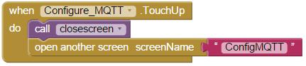
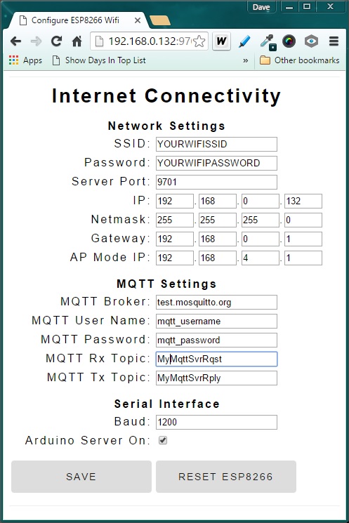
Configuration Mode

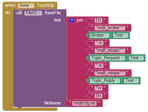
The configuration screen from the last iteration of this project was modified to add the new MQTT parameters. Just as before, this screen is accessed by entering the ESP8266 IP (or domain name) with it’s assigned web server port with the following suffix :

http://192.168.0.133:9705/config

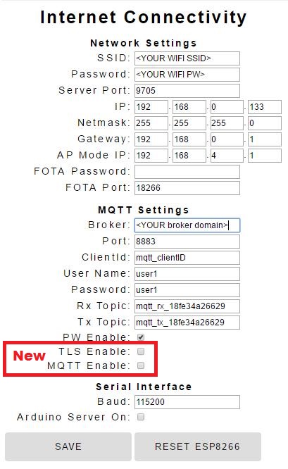
If you want to switch to the TSL MQTT operating mode at power-up, just check the 2 new boxes, click SAVE, and then RESET ESP8266.

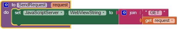
A URL has also been provided to switch modes within your application code:

http://192.168.0.133:9705/?request=MqttSslOn

This will change the EEPROM content to switch modes and reset the ESP8266 so it starts-up in the selected mode.

MQTT Mode

When the ESP8266 starts up in MQTT mode with TLS connection enabled, it will respond to server requests just like it did in the last iteration of this project. And switching back to ESP web server/configuration mode is simply a matter of sending the request in an MQTT message:

/?request=HttpOn

Conclusion

We now have a secure MQTT connection to the ESP8266. Here is the project code link again. And with careful management of the RAM (heap), it will perform reliably. More functionality in this case requires the distribution of tasks between two operating modes which are only loaded in memory when needed. This technique can be used in other cases as well to stretch the capabilities of this amazing little system on a chip (SoC) we call ESP8266.


Loading

Share This:
FacebooktwitterredditpinterestlinkedintumblrFacebooktwitterredditpinterestlinkedintumblr

Triple Server Update – Part 3: More Server Features

server_update_part3

More Server Features

Ever heard the saying “some’s good, but more is better” ? That idiom certainly rings true when it comes to the capabilities of the multi-purpose server I began developing recently.

The Triple Server introduced with this series initially supported http, mqtt and coap. Subsequently, coap was dropped and replaced with the addition of an Arduino interface. Web configuration was also introduced.

But even then, the system lacked a few highly desirable features. This update builds upon the basic  structure developed so far. Here are the new capabilities introduced with this update:

  • Configurable FOTA port and password
  • Configurable MQTT connection port and client id
  • URL decoding for configurable parameters with special characters
  • FOTA – sketch embedded wireless firmware update support
  • MQTT topics linked to ChipID(MAC)
  • Support for MQTT connection password enabled
  • Unsolicited Arduino MQTT Publications
  • Current GMT added to http header

There features are individually portable. When needed, they can be a great addition to many different IoT projects.

And in case you have not seen the prior posts in this series, here is the story from the beginning:

ESP8266 Triple Protocol Server

Triple Server Update – Part 1: Serving Arduino

Triple Server Update – Part 2: Web Configuration

Triple Server Update – Part 3: More Server Features

Let’s get to the details of the implementation…

Web Configuration

Starting with the Web Configuration panel:

WebConfig
FOTA password and network port settings are added to the configuration page options. When a FOTA password is specified, the user will be prompted to enter it prior to proceeding with a firmware update.

A setting for the MQTT client id has also been included with this update. The past versions of this project simply set the client id to the MQTT username. Finally, a check-box has been added to enable MQTT password connections.

However, the remaining MQTT connection options specified in MQTT Version 3.1.1 such as a last will message have not been implemented in this project. There additional options were not considered essential for this application.

URL decoding

The parameters updated on the Web Configuration page are passed from the html web code back the ESP8266 sketch code using an http “GET” request. Each parameter is added to the URL, a method that can easily be parsed by the ESP8266 c-code using the functions imported from the EspressIf SDK.

This all worked well until special characters were introduced in a password string. In these cases, the special characters are URL encoded, which converts the special characters into something an URL will accept. For example, a space is considered a special character and gets converted to “%20” in an URL.

The problem occurs when the parameter is saved. If “Hello World” is sent as an URL parameters, it becomes “Hello%20World”. This situation is resolved by using an URL decoder prior to saving the value. This restores the parameter to it’s original value, “Hello World” in this example.

Here’s the code used for URL decoding. It should be fairly easy to follow. The basic algorithm looks for a “%hh” code and converts it back to the original “special character” value in the string:


  1. /********************************************************
  2.  *  URL Message Decoder
  3.  ********************************************************/
  4.  
  5. int url_decode(char *encoded_str, char *decoded_str) {
  6.    
  7.     // While we're not at the end of the string (current character not NULL)
  8.     while (*encoded_str) {
  9.         // Check to see if the current character is a %
  10.         if (*encoded_str == '%') {
  11.     
  12.             // Grab the next two characters and move encoded_str forwards
  13.             encoded_str++;
  14.             char high = *encoded_str;
  15.             encoded_str++;
  16.             char low = *encoded_str;
  17.     
  18.             // Convert ASCII 0-9A-F to a value 0-15
  19.             if (high &gt; 0x39) high -= 7;
  20.             high &amp;= 0x0f;
  21.     
  22.             // Same again for the low byte:
  23.             if (low &gt; 0x39) low -= 7;
  24.             low &amp;= 0x0f;
  25.     
  26.             // Combine the two into a single byte and store in decoded_str:
  27.             *decoded_str = (high &lt;&lt; 4) | low;
  28.         } else {
  29.             // All other characters copy verbatim
  30.             *decoded_str = *encoded_str;
  31.         }
  32.     
  33.         // Move both pointers to the next character:
  34.         encoded_str++;
  35.         decoded_str++;
  36.     }
  37.     // Terminate the new string with a NULL character to trim it off
  38.     *decoded_str = 0;
  39. }

FOTA Support

Firmware over-the-air (FOTA) is a very useful option to include with your sketch. The Arduino makes this capability very clean and easy to embed in your code. I found it very useful for debugging code, as it freed up the serial port for test messages. The drawback, however, is that FOTA reduces your effective maximum sketch size in half. This was not a problem in this project, which currently only uses 26% of the available 4MB of my ESP8266-12 flash chip. Just be aware if you are using an older ESP8266-1 with this project, FOTA cannot be used as the sketch uses more than 50% of the 512K flash installed on many of the older ESP8266 versions.

Here is the implementation in this sketch:

A function was added and called in the setup() function.

init_FOTA();


  1. void init_FOTA() {
  2.     String buff;
  3.     int pt;
  4.     //Hostname defaults to esp8266-[ChipID] (no change to default, which is unique (ChipID = last 3 MAC HEX)
  5.     //ArduinoOTA.setHostname("myesp8266");
  6.     
  7.     //Set FOTA Network Port
  8.     GetEepromVal(&amp;buff, EEPROM_MQTT_PT, EEPROM_INT16);
  9.     pt = atoi(buff.c_str());
  10.     ArduinoOTA.setPort(pt);
  11.      
  12.     //Set OTA authentication (password)
  13.     GetEepromVal(&amp;buff, EEPROM_FOTA_PW, EEPROM_CHR);
  14.     ArduinoOTA.setPassword((char *)buff.c_str());
  15.     
  16.     ArduinoOTA.onStart([]() {
  17.         Serial.println("Start");
  18.     });
  19.     ArduinoOTA.onEnd([]() {
  20.         Serial.println("\nEnd");
  21.     });
  22.     ArduinoOTA.onProgress([](unsigned int progress, unsigned int total) {
  23.         Serial.printf("Progress: %u%%\r", (progress / (total / 100)));
  24.     });
  25.     ArduinoOTA.onError([](ota_error_t error) {
  26.         Serial.printf("Error[%u]: ", error);
  27.         if (error == OTA_AUTH_ERROR) Serial.println("Auth Failed");
  28.         else if (error == OTA_BEGIN_ERROR) Serial.println("Begin Failed");
  29.         else if (error == OTA_CONNECT_ERROR) Serial.println("Connect Failed");
  30.         else if (error == OTA_RECEIVE_ERROR) Serial.println("Receive Failed");
  31.         else if (error == OTA_END_ERROR) Serial.println("End Failed");
  32.     });
  33.     ArduinoOTA.begin();
  34.     Serial.print("FOTA Initialized using IP address: ");
  35.     Serial.println(WiFi.localIP());
  36. }

Note that the FOTA port and password values are set from values stored in EEPROM. That means they can be set from the application, so the sketch does not require modification to change the values.

More on that when we go through the updates to the Web Configuration page.

Unique MQTT topics

It a system is built using multiple devices, it may be desirable to ensure that each device sends and receives MQTT message over unique topic names. In order to link the MQTT topic to the ESP8266 device, the default topic now includes an expanded ChipID.

That is to say, while the official ChipID uses the last 3 hex characters of the device’s MAC address, the expanded id in this application uses all six MAC address hex values.

The implementation here simply appends the MAC to a topic prefix. The result is a topic name unique to each ESP8266 device.


  1.  void AddMAC(char * prefix, char * topic) {
  2.      uint8_t MAC_array[6];
  3.      WiFi.macAddress(MAC_array);
  4.      sprintf(topic,"%s", prefix);
  5.      for (int i = 0; i &lt; sizeof(MAC_array); ++i){
  6.           sprintf(topic,"%s%02x",topic, MAC_array[i]);
  7.      }
  8.  }

MQTT Password Connection

The initial design of the MQTT server in this project relied solely on the test.mosquitto.org broker. This simple test site does not offer the option of connecting with passwords. But, of course, a password protected connection is preferred. And recently, I had set up my own MQTT broker, with the capability to require username/password credentials with connections. So adding this to the ESP8266 based server was obviously needed.

Here is the mqtt connection code used to establish password enabled and password-free connections.  Note that the MQTT client class object uses a different client.connect() prototype when using a password to connect.:


  1. void MqttServer_reconnect(void) {
  2.     int fst=10;
  3.     bool connected = false;
  4.     // Loop until we're reconnected (give up after 10 tries)
  5.     while (!client.connected()&amp;&amp;(fst!=0)) {
  6.         Serial.print("Attempting MQTT connection...");
  7.         // Connect to MQTT Server
  8.         if(mqtt_pw_enable) {
  9.             connected = client.connect(mqtt_ci.c_str(),mqtt_un.c_str(),mqtt_pw.c_str()); 
  10.         }
  11.         else {
  12.             connected = client.connect(mqtt_ci.c_str()); 
  13.         }
  14.         if (connected) {
  15.             // Successful connection message &amp; subscribe
  16.             Serial.println("connected");
  17.             client.subscribe((char *)mqtt_rt.c_str());
  18.             fst--;
  19.         } else {
  20.             // Failed to connect message
  21.             Serial.print("failed, rc=");
  22.             Serial.print(client.state());
  23.             Serial.println(" try again in 5 seconds");
  24.             // Wait 5 seconds before retrying
  25.             delay(5000);
  26.         }
  27.     }
  28. }

Unsolicited Arduino MQTT Publications

The Arduino server has been designed to query the Arduino for sensor or pin status. These queries are initiated from external http or MQTT requests. But this structure did not allow the Arduino to independently publish messages to an MQTT topic. That capability has now been added. MQTT messages originating in the Arduino are now possible.

Adding this capability required a simple restructure of the serial part data handler. Now, any time the end of line is received from the serial port, the ESP8266 sends the response to the http or mqtt channels when initiated, and to the mqtt topic when received without an initial request originating from the ESP8266.

This change impacted the function that initiates requests to the Arduino via the serial port. With the revised implementation, the function no longer waits for a reply:


  1. String ArduinoSendReceive(String req) {
  2.     String fromArduino = "";
  3.     Serial.println(req);
  4.     long start = millis();
  5.     fromArduino = "";
  6.     return fromArduino;
  7. }

Instead, a new function, “MonitorSerialLine()”, was added to process all data received on the serial port, both initiated and unsolicited.


  1. void MonitorSerialLine() {
  2.     if(arduino_server) {
  3.         while (Serial.available()) {
  4.             // get the new byte:
  5.             char inChar = (char)Serial.read();
  6.             // add it to the inputString:
  7.             SerialInString += inChar;
  8.             // if the incoming character is a newline, set a flag
  9.             // so the following code can process it
  10.             if (inChar == '\n') {
  11.                 NewSerialLineRx = true;
  12.             }
  13.         }
  14.         //Send Received String as MQTT Message
  15.         if(NewSerialLineRx) {
  16.             //If not server request, just forward Arduino Message to MQTT
  17.             if(active_svr_rqst == SVR_NONE) {
  18.                 active_svr_rqst = SVR_MQTT;  
  19.             }
  20.             Server_SendReply(active_svr_rqst, REPLY_TEXT, SerialInString);
  21.             active_svr_rqst = SVR_NONE;
  22.             SerialInString="";
  23.             NewSerialLineRx=false;
  24.         }
  25.         //Check for timeout for Arduino Server requests
  26.          if(active_svr_rqst != SVR_NONE) {
  27.              if(start_wait==0) start_wait = millis();
  28.              if( (millis() - start_wait)  &gt;5000 ) { //5 sec timeout
  29.                   SerialInString = "no arduino reply received";
  30.                   Server_SendReply(active_svr_rqst, REPLY_TEXT, SerialInString);
  31.                   //Reset Request Parameters
  32.                   active_svr_rqst = SVR_NONE;
  33.                   start_wait=0;
  34.                   SerialInString="";
  35.                   NewSerialLineRx=false;
  36.              }
  37.          }
  38.     }
  39. }

Current GMT

gmt

The http response header requires an identification of current GMT (for the Date header) and a current date offeset (for expiration headers). Prior versions of this project simply added hard-coded, static values for these headers. While it did no impact the http response transmission, it was obviously inaccurate header content.

In order to create accurate date headers, current GMT must be known. So time is now retrieved from a NIST server. This required an initialization routine to be run in the sketch’s setup() function. The offset is set to 0 so we get GMT when time is requested.


  1. void init_GmtTime() {
  2.     configTime(0, 0, "pool.ntp.org", "time.nist.gov");
  3.     Serial.print("\nWaiting for time");
  4.     while (!time(nullptr)) {
  5.         Serial.print(".");
  6.         delay(1000);
  7.     }
  8.     Serial.print("\r\nTime has been acquired from internet time service\r\nCurrent GMT: ");
  9.     time_t now = time(nullptr);
  10.     Serial.println(ctime(&amp;now));
  11. }

Here is how time is now retrieved when creating an http header:


  1. String gmt,expire;
  2. time_t now = time(nullptr);
  3. gmt = ctime(&amp;now);
  4. now += 3600 * 24;  //Expires in 1 day
  5. expire = ctime(&amp;now);
  6. gmt = gmt.substring(0,3) + "," + gmt.substring(7,10) + gmt.substring(3,7) + gmt.substring(19,24) + 
  7. gmt.substring(10,19) + " GMT";
  8. expire = expire.substring(0,3) + "," + expire.substring(7,10) + expire.substring(3,7) + 
  9. expire.substring(19,24) + expire.substring(10,19) + " GMT";

The string returned from a call to ctime() is in a different format than what is needed in the http. The String class “substring” method is uses to re-sort the ctime() string into the needed http header format.

ctime() format:

Mon Mar 14 08:23:14 2016

http header format:

Mon,13 Mar 2016 08:23:14 GMT

In Closing

This update establishes a solid framework for building IoT projects with both http and MQTT server support. While Arduino is used in the example, any external device with a standard serial link can also be easily added to this structure. And when the system is deployed, updates can be deployed wirelessly, eliminating the need to connect a physical serial interface to the system.

Here is the updated GitHub repository for this project.

I hope you find this information useful…

Loading

Share This:
FacebooktwitterredditpinterestlinkedintumblrFacebooktwitterredditpinterestlinkedintumblr

MQTT for App Inventor – Adding Configurable Settings

App Inventor to MQTT Communication

In my last post, a basic MQTT client portal for App Inventor was introduced. As result, there has been some interest expressed for TCP socket support. Note that the implementation presented relies on WebSockets. Due to security vulnerabilities, pure TCP sockets are simply not possible with this design. If TCP sockets are needed for MQTT communication at your IoT device, a broker capable of both WebSockets and TCP sockets should be used – Websockets on the App Inventor side, and TCP sockets on the IoT device end.

Adding Configurable Setting

My next step was to refine the App Inventor project to support configurable MQTT setting.

NOTE: If you just want to review and use the updated App Inventor project without the walk-through that follows, simply use the files provided in this Github repository.

The first challenge while adding this capability was the inability to grant file system access to the JavaScript code. Native Android Apps can overcome this with a change to the App’s manifest file. But App Inventor does not expose this application setting.

So the App Inventor file component had to be used to read and write to the file system. The configuration file settings are then passed on to the JavaScript to update the MQTT connection parameters.

mqtt_cfg

App File Location

This App now uses two files stored on the Android device. These files have been moved to a common location which should be the same on most Android devices:

File Description
/sdcard/mqtt/mqtt_appinventor.html The JavaScript MQTT App Inventor Server
/sdcard/mqtt/cfg.txt MQTT Configuration

Configuration file

For this example, 3 parameters are configurable:

  1. Broker: This can be any on-line broker, on your own network or either publicly or privately provided.
  2. Request Topic: MQTT topic used to send a client request
  3. Reply Topic: MQTT topic used to reply results to the client.

Since this example uses the publicly available broker ‘test.mosquitto.org’, username/password authentication is not provided. You could easily be add this to the example provided here, however, if you are using a broker requiring authentication.

The file is formatted as a JSON string. This makes it very easy for the JavaScript to parse the values. The first time the App is run, these configurable parameters are set to the values shown in this JSON string:

{
“mqtt_broker”:”ws://test.mosquitto.org:8080/mqtt”,
“mqtt_txtopic”:”MyMqttSvrRqst”,
“mqtt_rxtopic”:”MyMqttSvrRply”
}

App Inventor File Read/Write

When the screen used to edit the configurable parameters is open, it first reads the cfg.txt file, extracts the parameter setting, and uses those values to populate the screen fields.

But when using App Inventor, there are no (at least none that I am aware) libraries available for parsing JSON. So I created the procedure “GetParam”, which extracts the cfg.txt values with 3 calls, one for each parameter.

readfile

Two values are determined initially in order to extract the value. First is the position in the string that the value starts. The other value is the string length. These values are determined by using App Inventor’s string search (starts at) feature to find something unique (StartPiece and LenPiece) around the value wanted, and an offset from the parameter value’s exact position in the string.

getparam

Once extracted, the “Edit Configuration” screen is populated with the values from this file.

cfg_gui

Saving the values is just the opposite. The values from the screen are formatted into a JSON string and then saved back to the same file, cfg.txt.

save

When this screen is exited, the new configuration values are sent to the JavaScript code. The JavaScript uses these new values and closes, then opens the MQTT connection with the new values. Here is how that has been implemented…

Updated Main Screen

As I have gained knowledge coding with the App Inventor, it became obvious that meaningful names were needed for project components. Much to my surprise, this does not extend to the main screen. It is called “Screen1” by default, and cannot be changed.

The screen GUI was changed somewhat for this update. Two new buttons were added. One to open the configuration screen and one to exit the application. The components were also move to the bottom of the screen (don’t want to cover the mosquito, do we?).

main

Every time the main screen is open, it’s 100 ms timer restarts. That is where the command is sent to the JavaScript to update the configuration settings.

Once.

It is sent 1/2 second (500 ms) after the screen is open. An important note: I found that the command did not execute if initiated concurrently with the opening of the screen. So the 500 ms delay (5 timer iterations) was introduced using a timer, which works every time.

timer

At 500 ms, the cfg.txt file is read. “CFG:” is inserted at the beginning of the string before being sent to JavaScript via the WebViewString.

sendcfg

A handler is also included for the first time this application is run. In that case, the cfg.txt file does not exists. As result, an exception is thrown when attempting to “ReadFrom” the file. An error handler was added for this condition.

error2

Error 2101 occurs when the file does not exist. In this case, a file is created with default values for the configurable parameters.

JavaScript for Configurable MQTT

The JavaScript also required revisions to support MQTT configurable parameters. The original version only handled IoT requests. These were identified with ‘GET:’ as the first 4 characters. Similarly, the added configuration command is now recognized as WebViewStrings beginning with “CFG:”


  1. // 10 Hz WebViewString polling timer function --------------------------------------&gt;
  2. function AppInventorServer() {
  3. var request = window.AppInventor.getWebViewString(); // Get WebViewString
  4.     if(request.substring(0, 4)=="GET:") {                // Validate request
  5.      window.AppInventor.setWebViewString("");         // Reset String (process once)
  6.         $("#request").val(request.substring(4, request.length)); //set request html textbox
  7.         SendMqttRequest();                               // Send Mqtt Request
  8.     }
  9.     if(request.substring(0, 4)=="CFG:") {                // Validate request
  10.      window.AppInventor.setWebViewString("");         // Reset String (process once)
  11.         var cfgpar = JSON.parse(request.substring(4, request.length));
  12.         txtopic = cfgpar.mqtt_txtopic;
  13.         rxtopic = cfgpar.mqtt_rxtopic;
  14.         mqtturl = cfgpar.mqtt_broker;
  15.         client.disconnect();
  16.     }
  17.     setTimeout(AppInventorServer, 100);   // run AppInventorServer() in 100 ms
  18. }

As you can see, parsing and extracting values from a JSON string is very simple and straight-forward with JavaScript. Once the new values are set, the MQTT broker connection is updated with a call to ‘client.disconnect()’.


  1. // Callback executed upon MQTT broker disconnection --------------------------------&gt;
  2. client.ondisconnect = function(rc){
  3. client.connect(mqtturl);
  4. };
  5. // Callback executed upon MQTT broker connection -----------------------------------&gt;
  6. client.onconnect = function(rc){
  7. client.subscribe(rxtopic, 0);
  8. };

Improving the Arduino Digital Commands

The original project used hard-coded values for the Digital Get and Set commands. Ok for an example, but not so good if you need access to a channel outside the card-coded value. That was rectified with this update, which now supports digital channel selection.

dig_new2

Select “Set Arduino Digital Channel” and a new screen is open. This screen allows you to select the channel to set.

digital_sel

This screen is open with a “start value” received from the main screen that called it.

select_digit

The value returned when OK is clicked depends on the startValue. If it is a “Set” command, an Arduino SetDigital request string is returned. The selected channel and logic state from the screen’s selections are also returned with the request.

Notice that a call to close the screen is made before the main screen (Screen1) is re-opened. That is necessary when returning a startValue. If the screen is not closed, it remains open for the duration of the App execution.

Another call to this window will open another instance of the window. This is effectively a memory leak which will crash you Android device eventually. Takeaway: Close the screen before opening a new screen when passing a start value to avoid memory leaks.

As you can see, a similar value is returned for “Get” requests. But when “Get” requests are received, the channel state is not selected, it is returned from the request. When this screen is open with a “Get” request, the channel state selection GUI is suppressed.

get_digit

Sending the Arduino Digital Request

When the Digital channel selection screen is closed, the main screen is reopened. But how does it know to send the Arduino command to MQTT? After all, the screen is opened fresh, just like when the app is started.

Not quite. Remember the ‘startValue’ returned from the digital selection? That is checked to determine whether an arduino request is needed. It is done in the 100ms timer callback.

timer

At 500 ms after the screen is open, the MQTT configuration is sent to the JavaScript. But then, at 1000 ms (10 100 ms intervals), the startval string is check for a non-null value. If a string is present, it is sent to the JavaScript via the WebViewString, by calling the SendRequest procedure.

send_request

Exiting the Application

Just one more thing and we are done with this update. I thought it would be nice to add an ‘Exit’ button to close the app. What I found was that it required several clicks before the app would actually close. What was happening was that every time a different screen returned to the main screen, the previous main screen remained open and a new main screen instance was created.

Not exactly what I had in mind. Another memory leak!

This was corrected by adding a ‘close screen’ before each time one of the two added screens was open. This guarantees only one screen is open at a time while the app is running.

cfg_mqttt

With this correction, the Exit button works as intended, with only one click required.

In Closing

This example should provide a framework for anyone needing to use MQTT with an App Inventor project. The main caveat is that a broker that supports WebSockets is required. I leave it up to you as an exercise to add username and password credentials to the mqtt connection settings. The basic structure is here. And it should also be a simple task to add “GetAnalog” to the Arduino request options. Go ahead, you can do it! If you need it.

Again, here are the project files.

I hope you find this information useful…

Loading

Share This:
FacebooktwitterredditpinterestlinkedintumblrFacebooktwitterredditpinterestlinkedintumblr

Triple Server Update – Part 2: Web Configuration

Have you ever moved your ESP8266 system from one Wifi location to another? Or perhaps made an extra one for your friend? In many cases, the initial setup requires a change to the sketch, to adjust the Wifi parameters to match the new access point—that is—unless the local settings are stored in the ESP8266 EEPROM.

What’s great about the EEPROM is that once updated, the configuration is non-volatile, That is, the values remain the same after the system power is removed and re-applied.

This post provides a method of setting and saving parameters likely to change with WiFi location, without changing the installed firmware sketch.

Once you’ve got you IoT device finished, you really should not have to modify the software again. That is, unless enhancements are made or bugs corrected.

Configurable Parameters

I started out with intentions on building a reusable configuration template. This would include the parameters most likely to change with system location and cloud-based servers used.

Using the Triple Server sketch I had developed recently as a test case, the configurable network and MQTT parameters  were first identified. Then, these parameters were mapped to the ESP8266 EEPROM.

For the project presented in this post, the following parameters were singled out to be configurable:

  • WIFI SSID
  • WIFI Password
  • IP – Static IP assigned to ESP8266 when used in Station mode
  • NM – Network Mask
  • GW – Gateway (Wifi Router IP)
  • AP – Static IP assigned to ESP8266 when used in Access Point mode
  • Web Server network port
  • MQTT Broker
  • MQTT Username
  • MQTT Password
  • MQTT Request Topic
  • MQTT Reply Topic
  • Serial Port baud
  • Arduino Server Enable

EEPROM Memory Map

The ESP8266 EEPROM configuration space is typically the first 512 bytes of memory. And here is how I allocated the configurable parameters to this EEPROM.

Parameter EEPROM Default Size(bytes)
WIFI SSID 0x10 YOURWIFISSID 32
WIFI Password 0x30 YOURWIFIPASSWORD 16
IP0 - IP Byte 1 0x40 192 1
IP1 - IP Byte 2 0x41 168 1
IP2 - IP Byte 3 0x42 0 1
IP3 - IP Byte 4 0x43 132 1
NM0 - Network Mask 0x44 255 1
NM1 - Network Mask 0x45 255 1
NM2 - Network Mask 0x46 255 1
NM3 - Network Mask 0x47 0 1
GW0 - Gateway 0x48 192 1
GW1 - Gateway 0x49 168 1
GW2 - Gateway 0x4A 0 1
GW3 - Gateway 0x4B 1 1
AP0 = Access point 0x4C 192 1
AP1 = Access point ox4D 168 1
AP2 = Access point ox4E 4 1
AP3 = Access point ox4F 1 1
Server Port 0x50 9701 2
MQTT Broker 0x60 test.mosquitto.org 32
MQTT User Name 0x80 mqtt_username 32
MQTT Password 0xA0 mqtt_password 32
MQTT Request Topic 0xC0 MyMqttSvrRqst 32
MQTT Reply Topic 0xE0 MyMqttSvrRply 32
Serial Baud 0x100 1200 3
Arduino Server Enable 0x108 1

Note that while 32 bytes are allocated for the character array parameters, this size is the maximum; it is not required to use this entire space. But each character array must be terminated in EEPROM with a NULL (0x00) character.

Webpage Structure

The next thing needed was a way to construct a webpage for viewing, altering, and saving these configuration parameters. All of the page rendering is done on the client side browser. With this in mind, the web page was developed using only html, css for styling, and Javascript.

In order to conserve program memory, the webpage source is saved into flash memory. Two character arrays were used, one for the html and JavaScript and a separate one for the css styling.

Next time, I am planning to separate out the JavaScript as well for cleaner partitioning. This can easily be done from the example code provided here and is highly encouraged as an exercise.

A token was placed at the top of the html character array for insertion of the css styling. Likewise, tokens have been placed in the Javascript jquery section for each configurable parameter. These tokens are replaced with the values stored in EEPROM prior to sending the completed webpage string to the client browser for rendering.

In this example:


  1.     $("#ssid").val("set_ssid");
  2.      $("#password").val("set_pass");
  3.      $("#ip_0").val("set_ip0");
  4.      $("#ip_1").val("set_ip1");
  5.      $("#ip_2").val("set_ip2");
  6.      $("#ip_3").val("set_ip3");
  7. .
  8. .

set_ssid is the first parameter token, which is replaced with the value read from EEPROM.

Here is what the rendered configuration page looks like:

config_page

The parameters are structured in html as a form with the two buttons shown. The save button is of type “submit” which sends all of the parameters back to the ESP8266 as a GET request for saving to the EEPROM.

But this merely saves the values back to EEPROM. Since the startup setup() function has already been run, the saved parameters do not become effect until an ESP8266 reset is performed. That is accomplished either with a power cycle or clicking on the “RESET ESP8266” button on this configuration page.

ESP8266 Webpage Request/Reply Code

Code was added to the ESP8266 URL request processing algorithm to handle web page requests. This is performed in the sketch’s Server_ProcessRequest function. For webpage requests, a slightly different URL format is used than requests to read a sensor.

The familiar example is the URL to get the sensor values:

192.168.0.132:9701/?request=GetSensors

When we want the ESP8266 to display the configuration page, enter:

192.168.0.132:9701/config

Note that there is no “?” for webpage requests. In order to parse the URL correctly for this case, the SdkWebServer_parse_url_params() function required modification.

Note that while the sketch provided in this example only supports the configuration page, a review of the code should make it obvious how to expand this to support your own custom webpages.


  1. // --------------------------------------------------------------
  2. // Serving Web Pages
  3. // --------------------------------------------------------------
  4. //
  5. // ------------- Load Config Page -------------------------------
  6. if(os_strcmp(pURL_Param-&gt;pParam[0], "config")==0) {
  7. GetEepromCfg(&amp;WebPage);
  8.     SdkWebServer_senddata_html(ptrespconn, true, 
  9. (char *) WebPage.c_str());
  10. }
  11. // -------------- Save config or Reset ESP8266 -------------------
  12. if(os_strcmp(pURL_Param-&gt;pParam[0], "ssid")==0) {
  13. if(os_strcmp(pURL_Param-&gt;pParVal[0], "reset")==0){
  14. // ------------- Reset ESP8266 -------------------------------
  15.      WebPage = reinterpret_cast&lt;const __FlashStringHelper *&gt;
  16. (PAGE_WaitAndReset);
  17.         SdkWebServer_senddata_html(ptrespconn, true, 
  18. (char *) WebPage.c_str());
  19.         os_timer_arm(&amp;ResetEspTimer, 3000, false); 
  20. }
  21.     else {
  22. // --- Save config to EEPROM and reload config page ------
  23. SetEepromCfg((void *)pURL_Param);        
  24.         WebPage = reinterpret_cast&lt;const __FlashStringHelper *&gt;
  25. (PAGE_WaitAndReload); //reload config page
  26.         SdkWebServer_senddata_html(ptrespconn, true, (char *) 
  27. WebPage.c_str());
  28. }
  29. }

The first parameter parsed is used to determine the webpage request type. This example only processes 2 possibilities. If the first parameter is “config”, the configuration page is rendered.

That is accomplished by building the webpage string. First using the template, and then substituting values for the css and parameter tokens. This is all done in the GetEepromCfg() function:


  1. void GetEepromCfg(String *page)
  2. {
  3.     *page = reinterpret_cast&lt;const __FlashStringHelper *&gt;
  4. (PAGE_NetCfg);
  5.     String css = reinterpret_cast&lt;const __FlashStringHelper *&gt;
  6. (PAGE_Style_css);
  7.     page-&gt;replace("ADDSTYLE",css); 
  8.     css = "";
  9.     
  10.     SetCfgPageWithEepromVal(page, "set_ssid", EEPROM_WIFISSID, 
  11. EEPROM_CHR);
  12.     SetCfgPageWithEepromVal(page, "set_pass", EEPROM_WIFIPASS, 
  13. EEPROM_CHR);
  14.     SetCfgPageWithEepromVal(page, "set_ip0", EEPROM_WIFI_IP0, 
  15. EEPROM_INT);
  16.     SetCfgPageWithEepromVal(page, "set_ip1", EEPROM_WIFI_IP1, 
  17. EEPROM_INT);
  18. .
  19. .

But if the first parameter is ssid, the value of the parameter must first be read in order to determine what action is requested. That is because the method of returning values to the ESP8266 code for both of the WebPage button is by submitting the form.

When the reset button is clicked, the ssid value is changed to “reset” before submitting. In that case (above code), as message is displayed indicating the ESP8266 is resetting. Note that a 3-second delay is implemented using a timer before the ESP8266 resets itself. That is necessary to allow time for the reloading of the configuration webpage to complete prior to the reset.

And in the case that the Save button is clicked, the ssid value from the webpage form input is not modified (set to “reset”) and thus, the values are simply saved to EEPROM.

Webpage Expansion

Again, all you need to do is add a suffix to the ESP8266 access url and add your processing code to expand this webpage server:

192.168.0.132:9701/YOURCUSTOMPAGE


  1. if(os_strcmp(pURL_Param-&gt;pParam[0], "YOURCUSTOMPAGE")==0) {
  2.     //Do whatever you want here to handle this request
  3. }

In case you missed part 1, the same code is used for this part 2. It is available on GitHub here.

In Closing

That’s it. A working framework for saving configuration parameters to ESP8266 EEPROM. And as an added bonus, you have a structure to expand this to render webpages of your own choosing. To control or monitor your own IoT things visually.

Hope you find this information as useful to you as it is for me…

Credits

Developing this example required research and reuse of material found in public domain sources. Special credit must be given to the following source which inspired my effort presented here. It also may be of use to others…

MQTT and Easy Web Config – by “The Godfather” – Posted October 22, 2015

Loading

Share This:
FacebooktwitterredditpinterestlinkedintumblrFacebooktwitterredditpinterestlinkedintumblr

Triple Server Update – Part 1: Serving Arduino

httpmqtt2arduino

Happy New Year! I’m picking things up right where they ended last year…

There were some basic enhancements needed to my Triple Protocol Server. But in the process of implementing the updates, the limitations of the ESP8266 resources were reached. To make room for the new features, something had to go.

In this case, the CoAP server was eliminated. The choice was obvious. This protocol consumed a large chunk of the available heap, leaving little room for program execution. As result, the system became unstable. CoAP also does not lend itself easily to web browser based clients.

So with that gone, a valuable new feature was added. A light-weight modification that did not significantly burden the system. Something that Arduino users should find extremely useful.

What is it?

An Arduino Serial Port Web Server

What? We already have access from the Arduino using the AT command set. “So what’s so special about this?”, you say.

Well…this implementation removes most of the web server tasks from the Arduino and puts it in the ESP8266. The only thing the Arduino needs to do is read small strings (requests) from the ESP8266 and return a small string back. This frees the Arduino to concentrate on sensor readings and control functions.

This balances the load on the two micro-controllers, reducing the load on the Arduino while fully leveraging the available power of the ESP8266 as a web server.

So how does this work?

It’s really quite simple. The ESP8266 web server is already in place. All that is needed is a few new URL-based (or MQTT topic payload) commands to provide web-based access to the Arduino resources.

The New Arduino Commands

The commands are parsed and decoded by the ESP8266. The command is reduced to a small string that is passed to the Arduino for action with it’s hardware resources.

URL Suffix ESP8266 to Arduino Arduino Reply
Set Digital Channel 04 HI /?arduino=SetDigital&chan=04&state=1 Arduino_SD041 Digital Channel 04 is HI
Get Digital Channel 04 /?arduino=GetDigital&chan=04 Arduino_GD04 Digital Channel 04 is HI
Get Analog Channel 04 /?arduino=GetAnalog&chan=04 Arduino_GA04 Analog Channel 04 is 2.234

The Arduino returns a reply to the ESP8266, which, in turn, is returned to the http or mqtt client.

This structure is similar to the slash (/) delineated bridge interface used with the Arduino Yun to communicate between it’s Arduino and Linux processors. Instead of using a pricey Arduino Yun, you can use any model Arduino along with the very inexpensive ESP8266. In this test case, I used a $7 Arduino nano clone.

The example presented here only includes the basic digital and analog access to the Arduino. The digital interface is obvious, setting or reading the state of each pin. The analog channel reads returns a voltage between 0 and 5 volts, based on the 10-bit Arduino ADC channel reading.

From this command set, it should be obvious how to expand it to include bus oriented sensors such as 1-wire temperature and i2c connected devices.

ESP8266 Sketch

The ESP8266 Arduino IDE sketch is based upon my triple server sketch presented in a prior post. The default parameters are defined at the top of the sketch in the section titled “Initial EEPROM Values”. These can be revised to match your network setting as described in Part 2 of this post, and in the sketch’s github repository.

Additional code was needed to support the Arduino requests. The commands received are repacked into a small string to be sent to the Arduino via the ESP8266 serial port. The server code to process the three recognized requests (Set Digital, GetDigital and Get Analog) shown here can easily be expanded for addition requests:


  1. // -----------------------------------------------------------------------
  2. // Serving Arduino via serial port
  3. // -----------------------------------------------------------------------
  4. if(os_strcmp(pURL_Param-&gt;pParam[0], "arduino")==0) {
  5. //-------------- Request = SetDigital ---------------------
  6. if(os_strcmp(pURL_Param-&gt;pParVal[0], "SetDigital")==0){
  7. if(os_strcmp(pURL_Param-&gt;pParam[1], "chan")==0) {
  8.           ArduinoRequest = "Arduino_SD";
  9.            ArduinoRequest += pURL_Param-&gt;pParVal[1];
  10.         }
  11.        else {
  12.             ArduinoRequest = "Invalid Request";  
  13.         }
  14.         if((os_strcmp(pURL_Param-&gt;pParam[2], "state")==0)&amp;&amp;(os_strcmp(
  15. ArduinoRequest.c_str(), "Invalid Request")!=0)) {
  16.             ArduinoRequest += pURL_Param-&gt;pParVal[2];
  17.         }
  18.         else {
  19.             ArduinoRequest = "Invalid Request";  
  20.         }
  21. }
  22.     //-------------- Request = GetDigital ----------------------
  23.     else if(os_strcmp(pURL_Param-&gt;pParVal[0], "GetDigital")==0){
  24. if(os_strcmp(pURL_Param-&gt;pParam[1], "chan")==0) {
  25.          ArduinoRequest = "Arduino_GD";
  26.             ArduinoRequest += pURL_Param-&gt;pParVal[1];
  27.      }
  28.       else {
  29.             ArduinoRequest = "Invalid Request";  
  30.      }
  31.    }
  32.     //-------------- Request = GetAnalog ----------------------
  33.     else if(os_strcmp(pURL_Param-&gt;pParVal[0], "GetAnalog")==0){
  34.      if(os_strcmp(pURL_Param-&gt;pParam[1], "chan")==0) {
  35.          ArduinoRequest = "Arduino_GA";
  36.             ArduinoRequest += pURL_Param-&gt;pParVal[1];
  37.         }
  38.         else {
  39.             ArduinoRequest = "Invalid Request";  
  40.         }
  41.    }
  42.    //-------------- Request is not recognized -----------------
  43.    else {
  44.     ArduinoRequest = "Invalid Request";  
  45.    }
  46.    //-------- Execute valid request &amp; get reply string --------
  47.    if(os_strcmp(ArduinoRequest.c_str(), "Invalid Request")==0) {
  48.      payld = ArduinoRequest;
  49.    }
  50.    else {
  51.     rparam.request = ARDUINO_REQUEST;
  52.        rparam.requestval = 0;
  53.        Server_ExecuteRequest(servertype, rparam, &amp;payld, ArduinoRequest);
  54.   }
  55.   Server_SendReply(servertype, REPLY_TEXT, payld);
  56. }

Arduino Sketch

A simple Arduino sketch is provided here  as an example of how to receive and process requests from the ESP8266. Using the low-end Arduino nano, this example uses a software serial port (Arduino digital pins 10 and 11) to communicate with the ESP8266.

Due to the limited bandwidth for reliable operation with this software port, the baud was reduced to 1200 baud. If a dedicated hardware serial port is used, such as found with the Arduino mega, the baud can be increased considerably.

The example provided is fully functional, yet simple enough to understand and build upon with even modest programming skills.

Part 2: Web-based ESP8266 Configuration

So there you have it, an ESP8266 web server sketch that supports Arduino communication using either MQTT or url-based http protocols. But there is more to this update. I’ve also added web-browser configuration of the Network and MQTT settings.

Read on here for the details…

Loading

Share This:
FacebooktwitterredditpinterestlinkedintumblrFacebooktwitterredditpinterestlinkedintumblr

ESP8266 Dual AT & Web Server Mode

Here is an exciting framework for fully utilizing the huge capabilities of the ESP8266.

This is an original.

Something that I have not seen anywhere before. You see, using this structure opens up many more possibilities and applications for this amazing device…

Most folks in the ESP8266 world seem to fall into one of two camps. The first group, typically diehard Arduino developers, want to use the ESP8266 as a serial to WIFI shield. A couple bucks to add WIFI to the very popular Arduino platform is most cost effective method of bringing it on-line. Much cheaper than alternative WiFi shields.

Others see the ESP8266 as a complete solution. It is often referred to as a System On a Chip (SoC). They not only use the ESP8266 for WIFI internet access, but also use the platform to read sensors, control “things”, process data and provide web server functionality.

Among The Examples

The majority of those that have delved into the ESP8266 world started by loading the serial to WIFI firmware often referred to as the AT command set. This is available as a binary file downloaded to the ESP8266 via it’s serial interface. That’s where I began my ESP8266 journey.

It was not long after my start that I searched for the AT firmware source code. Fortunately, it is available within earlier versions of the EspressIf SDK. You see, prior to version 1.0, many example applications were included in the development package. And yes, the AT command set was among these examples.

The other most useful example application is the IoT_Demo. This software has survived every release of the SDK, including the current version. This example provides a framework for a web server to make your “things” Internet accessible.

After studying the software structure of these examples I got to thinking…

Wouldn’t it be great to merge these two applications? So you benefit from both features?

It indeed did look feasible.

The combined application would not only service AT commands through the serial port, but also service http GET or POST commands via the Internet.

And that’s not all…

This single ESP8266 firmware application could also be used to read sensors and control devices.

I am stoked to say I have successfully merged these examples. This broadens the capabilities and applications of a single ESP8266 based system.

It works!

Here’s how…

ESP8266 Dual Server Architecture

The ESP8266 is used to perform 3 primary functions. First, it provides basic serial to Wifi capability using the standard AT command set that many first-time users tinker with. Note that since the design presented here includes the AT firmware source code, the command set can be expanded to also provide access to the Esp8266 Daq and Control features. This is depicted in the following diagram as two-way arrows from the AT Server.

dualserver

The ESP8266 also provides Web Server functionality. This feature operates completely independently from the serial AT Server. The web server responds to http GET commands received form the Internet via the built-in Wifi capability. Just like the AT Server, the Web Server has access to the Daq and Control functions.

And finally, the data acquisition (DAQ) and control function, also running independently from the other two features, controls all the Esp8266 outputs and receives all the sensor inputs. Because of the many possible sensors connected to the system, the DAQ function must be managed so that it does not monopolize the Esp8266 processor. This is accomplished by limiting it’s execution to the reading of one sensor each time the function is called.

Task Distribution

Separate callbacks are registered for each of the three ESP8266 primary functions. Both the AT and Web Server callbacks are event driven. They are only executed upon user request. The AT callback is executed anytime data is received on the serial port, while the Web Server callback is run upon receipt of an http GET request.

The callback for the Daq/Control features are different. This feature is set up to execute periodically (once every second) from a Timer callback. This keeps the sensor data fresh, available for consumption by the AT or Web Server, upon request.

AT Callback – The AT serial port server callback is installed in the uset_init() function when at_init() is executed. The AT server responds to any of the requests defined in at_cmd.h.


  1. at_funcationType at_fun[at_cmdNum]={
  2. {NULL, 0, NULL, NULL, NULL, at_exeCmdNull},
  3. .
  4. .
  5. {"+CIPSERVER", 10, NULL, NULL,at_setupCmdCipserver, NULL},
  6.   {"+CIPMODE", 8, NULL, at_queryCmdCipmode, at_setupCmdCipmode, NULL},
  7.   {"+CIPSTO", 7, NULL, at_queryCmdCipsto, at_setupCmdCipsto, NULL},
  8.   {"+CIUPDATE", 9, NULL, NULL, NULL, at_exeCmdCiupdate},
  9.   {"+CIPING", 7, NULL, NULL, NULL, at_exeCmdCiping},
  10.   {"+CIPAPPUP", 9, NULL, NULL, NULL, at_exeCmdCipappup},
  11.   {"+GETSENSOR", 10, NULL, NULL, at_exeGetSensorVal, NULL},

The new request, “+GETSENSOR”, has been added to provide a method for the serial port server to get the sensor readings. Upon receiving this request, the function at_exeGetSensorVal() is called. This function returns the current sensor reading over the ESP8266 serial port.


  1. void ICACHE_FLASH_ATTR
  2. at_exeGetSensorVal(uint8_t id, char *pPara)
  3. {
  4.       int isensno = atoi(++pPara);
  5.       switch(isensno) {
  6.             case 1:
  7.                   uart0_sendStr(tInside);
  8.                   break;
  9.             case 2:
  10.                   uart0_sendStr(tOutside);
  11.                   break;
  12.             case 3:
  13.                   uart0_sendStr(tAttic);
  14.                   break;
  15.             case 4:
  16.                   uart0_sendStr(tDht11);
  17.                   break;
  18.             case 5:
  19.                   uart0_sendStr(hDht11);
  20.                   break;
  21.             case 6:
  22.                   uart0_sendStr(pBmp085);
  23.                   break;
  24.             case 7:
  25.                   uart0_sendStr(tBmp085);
  26.                   break;
  27.             case 8:
  28.                   uart0_sendStr(aBmp085);
  29.                   break;
  30.             default:
  31.                   uart0_sendStr("out of range");
  32.                   break;
  33.       }
  34.       uart0_sendStr("\r\n");
  35. }

The requests are made by sending the following string over the serial port:

AT+GETSENSOR=n

“n” is the sensor number and corresponds to the case number in the code above.

As you can see, it is not difficult to add your own custom commands to the standard ESP8266 AT command set.

Web Server Callback – This application uses the Web Server code provided in the IoT_Demo example. The user_init() function sets up and connects to the local Wifi before launching the Web Server. The callback webserver_recv() is registered during the initialization sequence. That function is executed any time an http GET request is received.

For this demo application, the Web Server only responds to “request-GetSensors”. More requests can be added as noted in the code that follows. When received, the server replies by sending a JSON string containing all the sensor readings.


  1. LOCAL void ICACHE_FLASH_ATTR
  2. webserver_recv(void *arg, char *pusrdata, unsigned short length)
  3. {
  4.     URL_Param *pURL_Param = NULL;
  5.     char *pParseBuffer = NULL;
  6.     bool parse_flag = false;
  7.     struct espconn *ptrespconn = arg;
  8.     int i;
  9.     espconn_set_opt(ptrespconn, ESPCONN_REUSEADDR);
  10.     if(upgrade_lock == 0){
  11.           parse_flag = save_data(pusrdata, length);
  12.         if (parse_flag == false) {
  13.               response_send(ptrespconn, false);
  14.         }
  15.         pURL_Param = (URL_Param *)os_zalloc(sizeof(URL_Param));
  16.         parse_url_params(precvbuffer, pURL_Param);
  17.         switch (pURL_Param-&gt;Type) {
  18.             case GET:
  19.                 if(os_strcmp(pURL_Param-&gt;pParam[0], "request")==0) {
  20.                     <strong>// GetSensors is the only request the server currently supports</strong>
  21. <strong>                    if(os_strcmp(pURL_Param-&gt;pParVal[0], "GetSensors")==0) {</strong>
  22. <strong>                          json_send(ptrespconn, GET_SENSORS);</strong>
  23. <strong>                    }</strong>
  24.                     // Add additional requests here
  25.                 }
  26.                 json_send(ptrespconn, CONNECT_STATUS);
  27.                 break;
  28.             case POST:
  29.                   ets_uart_printf("We have a POST request.\n");
  30.                  break;
  31.         }
  32.         if (precvbuffer != NULL){
  33.               os_free(precvbuffer);
  34.               precvbuffer = NULL;
  35.         }
  36.         os_free(pURL_Param);
  37.         pURL_Param = NULL;
  38.     }
  39.     else if(upgrade_lock == 1){
  40.           local_upgrade_download(ptrespconn,pusrdata, length);
  41.             if (precvbuffer != NULL){
  42.                   os_free(precvbuffer);
  43.                   precvbuffer = NULL;
  44.             }
  45.             os_free(pURL_Param);
  46.             pURL_Param = NULL;
  47.     }
  48. }


Acquisition/Control Timer Callback – This callback serves as the application’s periodic loop() function. It is called once every second. The functions is mechanized as a state machine. In this example, 5 states are implemented, one for each sensor in the system. Exactly one state is executed each time the function is called. Upon completion of the sensor read, the code is set to execute the next state the next time the function is called. The code can be modified as needed to add or delete states and sensor hardware.


  1. LOCAL void ICACHE_FLASH_ATTR loop_cb(void *arg)
  2. {
  3.     char szT[32];
  4.     DHT_Sensor DHsensor;
  5.     DHT_Sensor_Data data;
  6.     DHsensor.pin = 5;  //GPIO14
  7.     DHsensor.type = DHT11;
  8.     int32_t temperature;
  9.     int32_t pressure;
  10.     //---------------------------------------------------
  11.     //This state machine reads 1 sensor each iteration
  12.     //---------------------------------------------------
  13.       switch(nTcnt%5) {
  14.             case 0: //Read first DS18B20 Temperature Sensor
  15.                 get_temp_ds18b20(1,1,tInside);
  16.                 break;
  17.             case 1: //Read second DS18B20 Temperature Sensor
  18.                 get_temp_ds18b20(2,1,tOutside);
  19.                 break;
  20.             case 2: //Read third DS18B20 Temperature Sensor
  21.                 get_temp_ds18b20(3,1,tAttic);
  22.                 break;
  23.             case 3: //Read DHT11 temperature and humidity Sensor
  24.                 DHTRead(&amp;DHsensor, &amp;data);
  25.                 DHTFloat2String(tDht11, ((9/5) * data.temperature)+32);
  26.                 DHTFloat2String(hDht11, data.humidity);
  27.                 break;
  28.             case 4: //Read BMP085 Temperature and pressure Sensor
  29.                 temperature = BMP180_GetTemperature();
  30.                 pressure = BMP180_GetPressure(OSS_0);
  31.                 os_sprintf(pBmp085,"%ld.%01d", pressure/3386,(pressure%3386)/1000);
  32.                 os_sprintf(tBmp085,"%ld.%01d", ((temperature*18)/100) + 32,(temperature*18)%100);
  33.                 os_sprintf(aBmp085,"%03d", 328 * (BMP180_CalcAltitude(pressure)/100000));
  34.                 break;
  35.             default:
  36.                 break;
  37.       }
  38. }

Want the code for this framework? Please feel free to use and modify it for your own custom requirements. It is available on Github here.

Testing the Code

Let’s test the dual server by sending a command over the serial port and via http GET. The command will retrieve sensors values read by the ESP8266. For this test case, the 1 second loop() function has been modified as follows to populate the sensor variables without actually reading any sensors.


  1. LOCAL void ICACHE_FLASH_ATTR loop_cb(void *arg)
  2. {
  3.     //-----------------------------------------------------
  4.     //This test code populates the variables associated
  5. //with the sensor values in lieu of actually reading
  6. //sensors. This code is used to test the functionality
  7. //of the dual server application. All variables are
  8. //set with fixed values except iTinside, which is
  9. // incremented by 1.5 degrees each time this function
  10. //is called.
  11.     //-----------------------------------------------------
  12. if(tI&lt;800) {
  13. tI += 15;
  14. }
  15. else {
  16. tI = 600;
  17. }
  18. os_sprintf(tInside,"%d.%d",tI/10,tI%10); //Sensor 1
  19. os_sprintf(tOutside,"%s","79.2"); //Sensor 2
  20. os_sprintf(tAttic,"%s","88.5"); //Sensor 3
  21. os_sprintf(tDht11,"%s","69.1"); //Sensor 4
  22. os_sprintf(hDht11,"%s","34.7"); //Sensor 5
  23. os_sprintf(pBmp085,"%s","29.7"); //Sensor 6
  24. os_sprintf(tBmp085,"%s","71.1"); //Sensor 7
  25. os_sprintf(aBmp085,"%s","555.0"); //Sensor 8
  26. }

AT Serial Server Test

The added function in this demo application to the AT command set is “AT+GETSENSOR=n”. “n” is filled in with an integer value representing the sensor number. Enter the following to test this new command:

Sensor Serial Port Command Expected Reply
Inside Temperature AT+GETSENSOR=1 increasing value in range 60-80 F
Outside Temperature AT+GETSENSOR=2 79.2
Attic Temperature AT+GETSENSOR=3 88.5
DHT11 Temperature AT+GETSENSOR=4 69.1
DHT11 Humidity AT+GETSENSOR=5 34.7
BMP085 Pressure AT+GETSENSOR=6 29.7
BMP085 Temperature AT+GETSENSOR=7 71.1
BMP085 Altitude AT+GETSENSOR=8 550.0

Web Server Test

The web server can easily be tested by entering a single URL in any web browser. In this demo application, the IP is hard-coded to “192.168.0.106” and the server responds to port 9703 requests. Thus, the test URL is:

http://192.168.0.106:9703/?request=GetSensors

And the expected reply will be the following JSON string:


  1. {
  2. "B_Pressure":"29.7",
  3. "B_Temperature":"71.1",
  4. "B_Altitude":"555.0",
  5. "DS_TempInside":"79.5", &lt;--NOTE: This value will range from 60-80 F in 1.5 degree increments
  6. "DS_TempOutside":"79.2",
  7. "DS_TempAttic":"88.5",
  8. "DH_Humidity":"34.7",
  9. "DH_Temperature":"69.1"
  10. }

Your demo application is working properly if the expected responses are observed.

In Closing

This opens up new possibilities. With this structure, you use the ESP8266 as an Arduino serial to WIFI shield. Yet at the same time use this same ESP8266 as a web server. And a sensor acquisition engine. And to control “things”. All you need to do is add meat to the bones provided here. What will you come up with?

I hope you find this information useful…

Loading

Share This:
FacebooktwitterredditpinterestlinkedintumblrFacebooktwitterredditpinterestlinkedintumblr

How To Unbrick FTDI Based Arduino Nano

nano_

Do you have an Arduino Nano that is non-operational? Failing to upload sketches? Behaving basically as a dead device. Non-responsive. Essentially a brick.

My Nano started behaving that way when I pulled it off the shelf to help someone with a project. This became another problem to be solved. It had to be corrected before using the device again.

So I searched for an answer on-line. It soon became clear that the root of the problem was the FTDI USB-to-serial conversion chip. Everyone was offering the same solution.

But, unfortunately, none of the information I found worked for my unique case. You see, my first attempt at solving this problem, in reality, made things worse. The contents of the FTDI flash had been altered. Making it unrecognizable and inaccessible.  I had to come up with an  answer to that issue first before addressing problem most users had been experiencing.

After much research and failed attempts, I have now come up with the complete solution. You may not need to do all these steps, unless you corrupted the nano’s EEPROM as I did.

Problem Discovery

After several unsuccessful attempts at uploading a compiled sketch, I had a closer look. The first thing to do was to monitor the devices serial port. This interface (USB at my PC) was spewing  “NOT GENUINE DEVICE FOUND!” endlessly at 115200 baud.

After some thought, I concluded that somehow the device claimed to be “Arduino-compatible” was in-fact, counterfeit. And somehow, the driver used to communicate with it’s FTDI interface chip knew it. Blocking it’s normal operation, replacing it with the message I was observing.

As it turns out, this “blocking message” was placed in the driver by the OEM, FTDI. Since everything worked initially, going back about a year and a half, but not now, a driver update had to be responsible for this new, unwanted behavior.

But what can be done to fix it?

From Bad to Worse

From what I had read, the problem was that the “updated” driver had a method to detect “non-genuine” chips. In those cases, the USB device descriptor ProductID (PID) was altered from 6001 to 0000.

The trick was to change the PID back to 6001. Fortunately, FTDI provides a utility to do just that. It is called FT_PROG, available here.

Changing the PID was easy with this program. Just start it with the nano plugged in, click on the scan icon, and your nano device settings are displayed. Just play with this program a bit and you will figure out how to change the Product ID.

FT_PROG

Yet after correcting my Product ID, the problem did not go away. I carefully looked at the instructions in an article with the “solution” and found one thing missing…

The Vendor ID was set to 0401 in the article and mine was 0403.

So I changed the nano VID to 0401. And that’s when things got really bad.

bad2worse

IMPORTANT: DO NOT CHANGE YOUR NANO’s FTDI chip Vendor ID.

With the VID modified, the device driver no longer recognized the device. And the FT_PROG utility could no longer find the nano. There was no way to change it back.

It appeared that the device was now permanently bricked. Useless. Unless the Vendor ID could be restored to the original value.

Fixing the Vendor ID

A review of the FTDI driver .inf files (ftdibus.inf and ftdiport.inf) uncovered the presence of many instances of “VID_0403”. I thought that changing it to “VID_0401” would make it recognize my altered FTDI device on the Arduino nano.

But trying this revealed yet another problem…

When attempting to install the driver, an error message popped up suggesting the driver had been tampered with. OK-OK, I changed the Vendor ID! The error occurs as result of a mismatch of the digital signature files (*.cat) with the driver files (*.inf).

No problem, just delete the .cat files and the driver installation should work. I was expecting a warning that the driver did not have a digital signature with “want to proceed anyway”, but that was not the case. It would not allow the installation to finish without the signature.

There is a way to resolve this new dilemma…

All that is needed is to disable driver signature verification. Instructions on how to do that can be found here.

With the signature verification disabled, I was able to install the driver with my modified (*.inf) files for the altered VendorID. This restore access to the FTDI device with the FT_PROG utility. The VendorID was then revised back to the correct value, 0403.

But I was still unable to download sketches to the nano.

Installing a Working Device Driver

In order to restore the original functionality to the FTDI chip, an older version of the driver must be installed. A version prior to the one FTDI released to brick “non-genuine” chips. You can get version 2.08.30 WHQL Certified here.

Scroll down to the “No Longer Supported” section to find this older driver. Download the zip file so can revise the *.inf files as needed. This driver will work to unbrick your FTDI device.

driver

But first the existing driver must be removed from your computer using the FTDI CDMUninstaller tool. This tool should be self-explanatory.

One more consideration. Windows regularly checks to see if any of your drivers are out of date. If your FTDI driver gets updated, possibly automatically,  you will be right back where this all began. With a bricked device.

To avoid this, you can trick Windows into thinking your older driver is in-fact, the most current. Just edit the ftdibus.inf and ftdiport.inf files as follows prior to installing the device driver:

change the line from:

DriverVer=07/12/2013,2.08.30

to:

DriverVer=07/12/2023,2.08.30

Credits

The following posts provided the essential information I needed to unbrick my Arduino-compatible nano…a.k.a China clone. Many thanks! These posts provide some of the details I have left out of this post. This info may prove to be useful in resolving your Arduino nano FTDI issues…

 Conclusion

Having a bricked device is always an unsettling feeling. Yet like most challenges in this DIY game, there is usually a remedy. Sometimes it takes some persistent effort to make things right. But what a relief when things are made whole again. Rest easy. Armed with the solutions presented here , you now know how to make those cheap Chinese clones behave as intended.

I hope this information helps solve your FTDI issues…

Loading

Share This:
FacebooktwitterredditpinterestlinkedintumblrFacebooktwitterredditpinterestlinkedintumblr

Expanding Arduino Serial Port Buffer Size

thingspeak

I recently came across a challenge while working with an Arduino serial interface. I suspect many others have also encountered the same issue. And the solution could save you precious time. So here it is…

After playing with an Arduino for a while, collecting sensor data, the logical next step is to add a method of saving this data for future consumption.

But where?

One option is to add an SD card or some similar storage device to your Arduino circuit. That would protect the data from system crashes. But there is a shortcoming with this approach…

You cannot get access to the data unless the Arduino is running, and you are located in the same area as the system. This approach, if relied solely for data storage, keeps your system isolated, Not exactly an IoT solution.

Saving the data somewhere independent of the hardware that first acquired the information makes more sense. In the cloud if possible.

Many turn to ThingSpeak. This free service supports up to 8 updates at a time. The API uses a single http “GET” request for this purpose. The strings are typically 100-150 characters long, data dependent of course.

No problem, right? Since the Arduino often uses a serial to WIFI device (like an ESP8266), all you need to do is write the string to a serial port. A very simple one-line sketch command.

Yet there lies the essence of the problem….

Really? What is so hard about writing a string to a serial port? Well, here is the rub…

You see, the Arduino Serial port buffers only hold up to 64 bytes by default. Try to send a string longer than 64 bytes and it will be truncated. Cut off at the buffer size. Not exactly what you want.

I’ve run into this and found that there are two different solutions. The one to use depends on whether you are using a hardware or software serial port.

It is important to note that these changes are at the Arduino core level. This means that every serial port used in all your projects are effected by this change. These minor file changes need to be undone for projects that work just fine with the default 64 byte buffer size.

The reason you may not want to expand the buffer all the time is that the buffer consumes valuable Arduino RAM. An ATmega328 based Arduino, typical in many models, only has 2048 bytes of run-time RAM available. With two separate serial port buffers (on for Tx, one for Rx), changing the buffers from 64 to 256 bytes  increases the RAM requirements from 128 bytes to 512 bytes. That is a full 25% of the available RAM for your entire sketch.

The Arduino Mega is the model of choice if extra RAM is important. This beast sports the ATmega2560 chip which provides 8192 bytes of RAM and 4 hardware serial ports.

Software Serial Buffer Expansion

The change for software serial ports require a simple modification of the file:

<base Arduino folder>\hardware\arduino\avr\libraries\SoftwareSerial\SoftwareSerial.h

Change:

__#define _SS_MAX_RX_BUFF 64 // RX buffer size

To:

__#define _SS_MAX_RX_BUFF 256 // RX buffer size

Hardware Serial Buffer Expansion

The change for hardware serial ports require a simple modification of the file:

<base Arduino folder>\hardware\arduino\avr\cores\arduino\HardwareSerial.h

Change:

__#define SERIAL_TX_BUFFER_SIZE 64
__#define SERIAL_RX_BUFFER_SIZE 64

To:

__#define SERIAL_TX_BUFFER_SIZE 256
__#define SERIAL_RX_BUFFER_SIZE 256


I hope this information proves to be useful….

Loading

Share This:
FacebooktwitterredditpinterestlinkedintumblrFacebooktwitterredditpinterestlinkedintumblr

Press Ctrl+C to copy the following code.
"