Are your ESP8266 flash attempts failing? Or perhaps not working at all anymore? Getting that annoying “Invalid head of packet” exception?
I have. Very frustrating…
And there aren’t many answers to be found on-line. What really got me steaming was the “Fatal error” messages at 115200 baud after I thought the flash completed properly. I have been there.
Over and over again…
Just when I was ready to give up…after many, many flash attempts, a flash will actually succeed. You think everything is good again, but the problem just keeps coming back…
What is wrong? Is this just a cheap Chinese trinket? An illusion of the Holy Grail? The ESP8266 specs look great. With such a cheap price tag that sucked you in? Or is there something your doing wrong?
Here is what I have found to be the problem…
And yes, there is a solution.
What many of us have experienced wit these ESP8266 modules, especially those that like to tinker and flash often, is the very low flash cycle count that the memory chips shipped with many of these modules will tolerate before failing. In my experience, flash failures start after only 20 flash cycles or so.
Then it only gets worse from that point on.
The good news is that the memory chips are not difficult to replace. And they are cheap when you order them with free shipping from the slow boat from China. You should be able to find them on AliExpress or your other favorite source. Here are some recent quotes for the different chips found on ESP8266 modules:
[wptg_comparison_table id=”3″]
From looking at the firmware binary header, it looks like the flashes are made for a 512 KByte flash chip (byte 3 upper 4 bits are 0). This would suggest that CURRENTLY, all that is used with the ESP8266 is 512 KBytes.
That is what I am using to replace the flash chip when they start to fail intolerably. I have recently replaced a 4MByte flash chip with a 512 KByte component, it worked flawlessly. With the same amount of space free for the application. You can clearly see that the ESP8266 SDK indicates the maximum firmware size as 512 KBytes.
I have been using the ESP8266-12 modules. The only added step needed for flash chip replacement from an ESP8266-01 is that the golden metal case must be removed to gain access to the SPI memory chip. This is not impossible, you just have to take your time, be patient, and careful.
I use a razor blade to pop the cover off. You just have to score the crease where the metal case meets the PCB. Only do this on the edge that is away from the PCB antenna. This minimizes the risk of damaging something. Eventually, the blade will breach the case bonding. When it starts to give, the rest of the cover will soon separate from the module – cover removed!
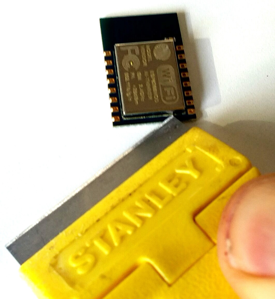
Take it slow so you do not cut yourself, damage the module, or snap the blade. I use a blade with a safety cover. It only require 5-10 minutes to remove the cover in this manner. I have done it to two modules so far with no damage incurred. I have seen some folks use a heat gun to remove the cover. This is too risky in my opinion.
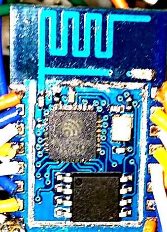
The SPI memory chip will be the obvious 8-pin device. Not to worry. While the ESP8266 would be very challenging to remove, not so with the memory chip. The pins are larger than the ESP8266, making them easier to remove. Just spot apply a hot soldering iron tip to each pin with a pointed object used to lift the pin while the heat is applied. One pin at a time. I found that a breadboard jumper to work for this purpose.
When you have the chip removed and are ready to install the new chip, remember to use the same orientation. A small dot on the chip identifies pin one. Just make a note before removing the old chip for reference. And, obviously, limit the amount of heat applied to each pin.
I am currently using my replacement SPI chips for development and have a decent supply on hand (only 32 cents per chip) to focus on project development, free from the agony of squandering time over recurring flash failures.
I’ll give an update when the replacement chips start to fail to flash. Hopefully, there will be an improvement from the original chips. More flash cycles before the first failure. We shall see. But I can live with it knowing a chip swap will chase this demon away, at least for a while.
Hope that you find this information useful…
Social tagging: ESP8266 flash failures > ESP8266 will not flash > How to unbrick ESP8266 > Invalid head of packet
Any news on that, i got a few esp8266 12, and they seem to flash correctly, but when rebooting i’m getting errors, and i tried a lot of firmware, so i was suspecting the hardware, and found your article.
Does it works better for you now?
Kris,
I have now been experiencing failure-free development. Starts up first time, every time. And no flash failures. As you know, development of firmware requires many flash iterations.
It was not always this way. My first few months working with the ESP8266 were very frustrating. It all came down to using a sloppy hardware setup. Once I ditched the flakey solder-less breadboard and jumpers and added some filtering capacitors, all those intermittent resets errors went away. Here are the details.
One more thought. I never had good results using Lua Node/MCU. Highly recommend using the SDK first or the Arduino IDE for ESP8266 second.
I was getting invalid packet err when flashing using the FTDI232 modules,,the ones I have are not that great, only 2 out of 10 would reprogram the ESP-201..
I switched to a crystal controlled usb-serial [D-SUN] uses prolific driver W7.
I have reprogrammed I suspect about 300-400 times and have had very few
2-3 invalid packet errs, I think crystal controlled is the key ……..
Now – using nodeMCu I send serial data to ESP and store it in a Var that is displayed on the web page. However to get the page to display the updated Var I must click on a web page button. Can anybody tell me how to trigger
the event just from the serial input,,I tried executing some button code , but this did not update page……I tried using uart:on but the gets in a restart loop
on 1st restart…the basic code is based on Indestructables Blinker Thing .. heavly modified…I think I will run out of mem before done.
Your setup is not clear to me. From your comment, it looks like you have an ESP running a lua script that will return the Var to a web page (hosted external to the esp), statically, when the web page is first loaded. But serial port changes to Var are not updated on the web page.
Is that your setup?
Or are you serving a web page from the esp?
The answer to your question depends on your setup.
From what you have disclosed, I would recommend:
1. Stop using nodeMCU/lua scripts for any ESP8266 projects. Among other things, your concern about running out of memory is valid and drastically limits your capabilities. You will find that the Arduino IDE or EspressIf SDK development environments are far more capable with much larger coding space available than lua scripts. If you are rendering the web page using a lua script, the page would need to be dynamically updated. Lua scripting is outside my scope of interest and expertise so you would need to get some advice on that elsewhere. I suspect it would be difficult to achieve what you are looking for without blowing your available memory,
2. Interrupts are supported on the GPIO pins (The serial Tx/Rx are GPIO1 and GPIO3). Setting up the Rx in interrupt mode will allow you to set a callback function that is executed every time a new “Var” value is received via the serial port. In this routine, you can “publish” the new “Var” value. Your web page can “subscribe” to these updates and update the displayed value everytime the ESP8266 publishes it in the callback function. The web page would subscribe to the data updates using jQuery AJAX. This, of course, assumes your web page is hosted external to the ESP.
3. It is also easy to setup a jquery timer event that triggers, say, once every second on your web page. That callback could easily “pull” the data from your ESP webserver, and update the displayed value with a jQuery call such as: $(“#myVarID”).html(NewVarValue); If the value did not change via the serial input to the ESP, the same value would be pulled and displayed as the last second. The downside to this is that pinging the ESP every second could drain the free heap. I have seen memory usage linger with frequent access, requiring some time to pass before the ESP returns the memory to the heap.
Good luck. Please feel free to clarify your setup if you need more assistance.
After flashing with no problems for some time now, I am suddenly having lots of problems flashing with an ESP-12e module attached to my own custom board. Flashes are reported as successful but the code appears corrupted and will not run. Is this similar to the symptoms you were seeing?
Following your lead, I am going to try replacing the flash memory to see if the problem disappears. I have already popped off the metal case and replacing looks straightforward. However, I am wondering — am I going to need to reload the bootloader unto the flash after I replace the flash chip? If you have any tips on that, I’d appreciate it. I use the Arduino IDE for my 8266 development, and that uses esptool.
Thanks,
-John
Hi John,
Thanks for your feedback. My first 2 ESP setups were a nightmare, worked great for the first 20 or so flashes before the trouble started. Sometimes the flashes worked, sometimes they wouldn’t. And the code did not always run as coded. Changing the flash chip would help, for a while. But the problems would return. Ultimately, the problems went away. And while the flash failures were the symptom, the flash memory chip was not the cause.
Since eliminating the cause, I have assembled and used 4 separate ESP12 boards, flashing them hundreds and hundreds of times without a single failure.
The difference?
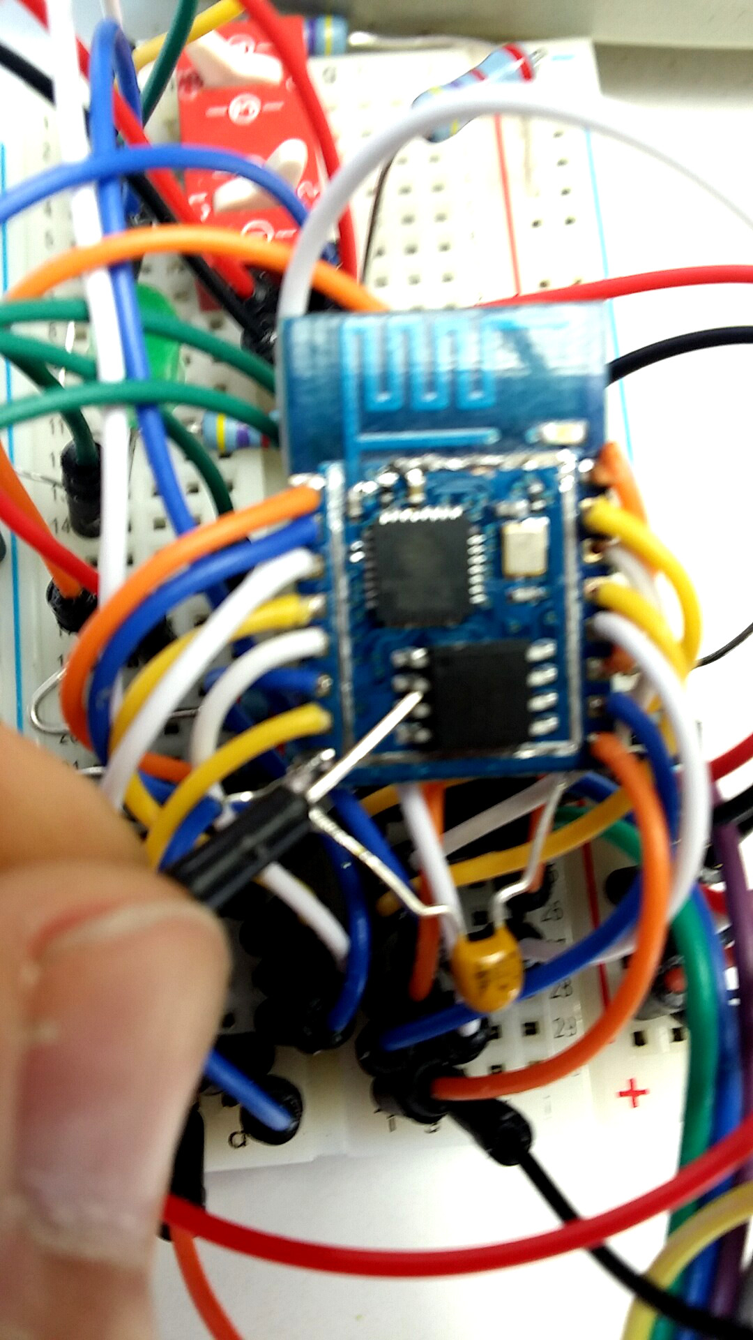
I believe the root problem with my first two setups was the unreliable assembly using solder-less breadboards and jumper wires. Even with this post, you can see I was still using the jumpers. Bad idea! Since moving to a fully soldered board, with terminal lugs for external interfaces, the flash failures have disappeared.
As I recall, there were no special procedures necessary to download a boot-loader after replacing the memory chip. I just used the ESP8266 flasher program initially to flash ESP_8266_BIN0.92.bin before using the Arduino IDE after the flash memory chip replacement. And that may not really be necessary before simply flashing with the Arduino IDE.
Currently, I use both the Arduino IDE and the EspressIf SDK for code development, and occasionally NodeMCU with LUA. Switching environments has been 100% successful since cleaning up my hardware construction.
I still have the original two ESP8266 modules that were flaky with the solder-less breadboard and long interface wire setup. I plan on rebuilding these using a clean, soldered board at some point to assess whether they are permanently damaged or fully functional with a better host board. That would ultimately answer your concern about flashing successfully once problems appear. I’ll let you know how that turns out. Just have not been motivated to mess with those prototypes since I now have multiple reliable boards on hand.
I suspect the flash memory chip on the ESP modules are susceptible to transients, with failures induced from exposure to fluctuating voltages and intermittent connections as result of the use of jumper wire.
Good luck. I strongly recommend using a 100% soldered board, proper power-supply capacitors. That has worked for me after countless initial frustrations.
Thanks for this thoughtful response. My board is 100% soldered but I had a pretty serious grounding issue for awhile that was making everything unreliable. It could be that did my flash chip in. Also, my board has decoupling caps but I didn’t have a .1uF very near the Vcc/GND connections of the module so I have also added that. With these changes I replaced the module and so far so good but we’ll see how it goes over time. 🙂
I was wondering if you think there might be much of a difference in the brands of modules. It seems there are some “fake” ESP-12e (for example: http://www.esp8266.com/viewtopic.php?f=5&t=3163) and I haven’t really been paying attention to whether I have genuine or fake ESPs. Maybe some are a bit more robust than others?
Hello,
i have an esp 12 and a i am using arduino IDE i thought i could simply remove the additional Flash Memory chip. The microcontroller in the esp chip has itself a Flash Memory. So why not using it directely without any additional Memory chip. That s what i am not well understanding!!
well i have removed the Memory chip but i can not upload the arduino skecth any more to the esp. Is this issue related to the “.json” board installed in the IDE? It is possible to use only the ESP without any additional chip Memory? what do you think?
thnx
The ESP8266 contains 64k of instruction RAM and 96k of data RAM. I am not aware of any way upload a sketch to this limited RAM that is used for program execution. Since this is RAM, not flash, the contents are gone when power is removed.
I still have the first two ESP8266-12 modules I started out with. But they are no longer used as I had reliability issues and possible sketch loading problems. And that was even after replacing the flash. It was most likely the result of my poor construction techniques. Since correcting the build, there have not been any sketch loading issues, and there have been more than a thousand successful loads now on my experimental ESP setup.
This is what I did to overcome sketch upload failures:
http://internetofhomethings.com/homethings/?p=605
Hello All,
im just a new about esp e-12, and faced to an unsolvable issue.. I have 8 of e-12 running nodemcu/lua and they work fine. Based on my experiences, I wanted to flash some additional e-12. It was done, and had no errors, using nodemcu flasher. But after a successful flash, i can not connect to the device via esplorer.
I do all the same as before, but there is no connection. I solder everything, gpio 2 and EN connected to + directly, gpio 15 and 0 to – directly during flash, and gpio0 to + after flash. it worked before…..
I use usb-ttl Prolific device. If I re-flash my “older” es-12, it works, and I can connect to.
Any suggestions? Do I have to use resistors as pull up/down, and a .1uF cap to +/- — do you thing it will solve this issues? It is not a stability issue, simply after flash, I cant connect, does not matter what speed I choose.
Thank you in advance for your support!!
G
While I am not sure how your hardware is set-up, I can tell you from my experience that a clean setup is essential for reliable flashing and eliminating unwanted resets. I have 10 ESP12 modules but currently only use one for development. It has been working reliably now for a year and has thousands of flash cycles on it, all without failures.
Here’s a few tips on the hardware setup I found to work very reliably:
http://wp.me/p5NRQ8-9L
And the basic schematic in this post (connect what you need to the IO):
http://wp.me/p5NRQ8-8y
If I could not connect, I would go back to the beginning, using the basic flasher most of us started with to load the original code back on the ESP12 & verify the AT commands work again (like “OK” returns from AT?, that is your “Hello World” test). No point in trying anything else if that does not work.
Hello,
I want to replace the flash memory of an ESP-01 and came across your blog posting. The Winbond website lists several chips starting with “W25Q40”, namely W25Q40CV, W25Q40CL, W25Q40BW and W25Q40EW. Which one should I take? Also, the Datasheet of the ESP8266EX states that the minimum flash size for supporting OTA updates should be 8 Mbit. What Winbond chip with that capacity would be compatible to the ESP-01?
Thank you!
I believe the ESP-01 has the same form-factor as the ESP-12 for the SPI flash chip (8-pin SOIC). If you are going through the trouble of replacing the chip, I would suggest using the higher capacity W25Q32 (32Mbit or 4 MByte). It should be compatible with your ESP-01. I got 10 of these chips on Ali-Express for $3.50 last year, no shipping charge. You will have to wait 1-2 months for delivery on the slow boat from China. however. They used all these terms in my invoice for the Winbond chip: W25Q32BVSSIG W25Q32 W25Q32B 25q32 W25Q32BVSIG 25Q32BVSIG
I have had great success with OTA programming and with this chip, you can have a large of amount of programming (Arduino IDE or SDK) while staying within the OTA parameters.
I found that after days of flawless flashing it went unreliable. My fix is a slower flashing procedure as detailed here: https://github.com/esp8266/Arduino/issues/2944<pre class="easycode;">
Stuff with your code!
</pre><pre class="easycode;">
Stuff with your code!
</pre>