 As I found myself staring at the information collected by the Mobile Weather Sensors, searching for ideas on how to best present the information visually, the reality hit me….
While this is a decent App for collecting information on-the-go, it data itself and the environment it is collected in does not lend itself well to real-time visualizations.
Two problems…
First of all, there is a significant lack of visibility of the smartphone screen outdoors. You could have developed the most magnificent display, with eye-catching vividly colored displays. Great inside, but the screen appears almost blank when taken outside in the direct sunlight. And that is where this mobile sensor system is most of the time.
The other issue is the slow moving, almost static values of the sensors. Temperature, humidity and pressure do not vary much moment by moment.
Despite the limited usefulness of GUI displays for this application, I decided to throw a few in anyways.
There is always something to be gained…
You see, these added screens can be used in any App. Providing quick and easy-to-implement options to display your data.
Since this App has been structured with a standard web page format (html to render the GUI, CSS to style and JavaScript for processing), JavaScript charting is the obvious and most logical choice for real-time visualizations of the sensor data.
The good news is that there are many options available.
This site provides access to 15 different Javascript Charting Libraries. D3.js seems to be the crowd favorite. It has lots of flexibility. But I did find it somewhat more complex to get started with, and the charts were not responsive to different screen sizes.
So I chose Chart.js. Why? It was quick and easy to implement. Yup, their claim actually rang true for this application “Simple, clean and engaging charts…”. And yes, they are also very responsive to the smaller smartphone screens.
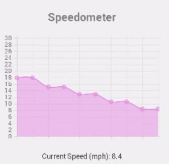
A Speed Chart
The first chart displays velocity. It is essentially a speedometer. The code simply updates and displays the last 10 speed values received from the GPS sensor. The current reading is displayed as the next point on the right side of a line chart. This new speed value pushes the other 9 readings one position left on the chart, with the left-most reading dropping off the chart.
As I mentioned, the smartphone display is nearly impossible to view outdoors in the direct sunlight. For a test of this real-time chart, I simply held my phone upright and rode my bicycle down the street. Using an independent Garmin GPS device for reference, I rode at varying speeds to confirm that the smartphone app display values correlated.
The current speed value (mph) is also displayed under the chart.
I was pleased to observe the accuracy of the display.
Perfect Widgets
No, there really is no such thing as “perfect”. But I have gotten a few gadgets from Perfect Widgets which have now been added to this application.
First, I tested a compass widget, using only the “heading” value from the smartphone’s GPS sensor. After reviewing a recording of the display, it became apparent that considerable lag occurred between a change in direction. The audio was recorded along with the display. While the sound quality is not great, it clearly illustrates the lag in responsiveness when direction changes.
The lag could easily be overcome my using the Android magnetometer sensor in place of the GPS heading value. But since we are focusing on the real-time sensor displays, that change will be pushed off into a future upgrade.
Clock Widget fed from GPS Sensor
Sure, you can readily extract the time from the phone or even pull up a timeserver. But for this Application, let’s use the GPS time-stamp.
So now a dynamically changeable clock image was needed…
Once again, I looked the the “Perfect Widgets” library for a clock gadget. In this case, 3 sliders must be updated to maintain the clock. One for each of the moving clock needles (Hours, Minutes, Seconds). Minutes and seconds are easy, since the are extracted from the Date object every time it is refreshed (a value from 0 to 59).
But the same hour is returned for 60 minutes. As we all know, analog clocks move smoothly minute-by-minute from 1 hour to the next. And so we must add a fraction equal to the current minute divided by 60 to get the current “partial hour”. The Date object also returns the hour as a number between 0 and 23. This must also be adjusted for our 12-hour analog clock widget.
var d = new Date(position.timestamp);
se.setValue(d.getSeconds(),false);
mn.setValue(d.getMinutes(),false);
if(d.getHours<13) {
    hr.setValue(d.getHours()+(d.getMinutes()/60),false);
}
else {
    hr.setValue(d.getHours() - 12 + (d.getMinutes()/60),false);
}
Here is what the gadget looks like…
Small Yet Useful App Update
Some times I have wanted to use the smartphone App alone.
Without the ESP8266 running…
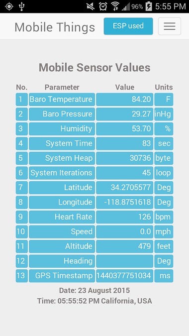
In those cases, I found it necessary to record sensor data while omitting the ESP8266 information. This was particularly useful in times when it was easier to check things out without taking the extra steps to activate my ESP8266 module.
The simple solution was to add a button to the top of the navigation bar to toggle enabling/disabling the use of the ESP8266 in the log file. The following screenshot shows this added button in the default “ESP used” state.
Conclusion
We now have a few real-time visual representations of the Mobile Sensor Data. There are many more possibilities for the creation of visual displays. Here again is the link that provides a reference to some of the best JavaScript charting tools available.
Want to see the code behind the charts I have present? The code developed thus far (Phases 1-4 of this project) is accessible on Github here.
I hope you find these tools useful in your projects…
Social tagging: Android charts > IoT Sensor display