Internet of Things

Mobile Web Sensors Using ESP8266 – Phase 2: Data Recorder

Collecting data from sensors and displaying them on your phone while you are on the go is great, but without a storage method the data is lost. Sure, you could snap a picture of the display, but that is just a frozen set of data points. And not in a format suitable for data analysis.

I thought this might be a difficult task. But much to my surprise, it was amazingly simple to save data to a non-volatile file on the smartphone’s SDcard.

Here is how it’s done…

Starting with the data collection framework from Phase 1 of this Mobile Sensor series, we now add code to record the sensor data as it is sampled. To make things simple yet useful, each data set will be saved in CSV (comma separated value) format. The file, consisting of a series of data sets, can then easily be imported as an excel spreadsheet.

The FileSystem API will be used to open and save the data to an Android device SDcard. Fortunately, the code developed for Phase 1 of this project already has the required permissions included so we can gain access to the OS file system. First, the projects res/xml/config.xml must include the following feature:

<feature name="File">
    <param name="android-package" value="org.apache.cordova.file.FileUtils" />
    <param name="onload" value="true" />
</feature>

And the AndroidManifest.xml file must include the permission:

<uses-permission android:name="android.permission.WRITE_EXTERNAL_STORAGE" />

Since there are two sources of inputs (the gps sensor and the ESP8266), two CSV strings are built at the time the data is received. The GPS CSV string is added to the “onGeoSuccess()” callback:

gpssavestring = position.timestamp + "," 
              + "," + long.substring(0, 12)
              + "," + latt.substring(0, 11) 
              +,"," + position.coords.speed
              + "," + position.coords.altitude;

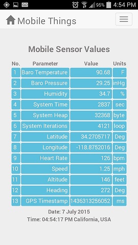
Five geo values are to be saved: UTC when coordinates were received, lat, long, speed and altitude.

Likewise, a CSV string is created each time the weather sensors are updated in the function updateWeatherSensorData():

 sensavestring = "," + thedata.B_Temperature 
               + "," + thedata.DH_Temperature
               + "," + thedata.B_Pressure
               + "," + thedata.DH_Humidity
               + "," + thedata.SYS_Time
               + "," + thedata.SYS_Heap
               + "," + thedata.SYS_Loopcnt + "\n";

Finally, the two CSV strings are concatinated and written to a file on the SDcard using the File System API:

//--------------------------------------------
//Update Save Data to File 
//--------------------------------------------
function saveData2File() {
	window.requestFileSystem(LocalFileSystem.PERSISTENT, 0, gotFS, fail);
}
function gotFS(fileSystem) {
    fileSystem.root.getFile("mydata/dsa.csv", {create: true, exclusive: false}, gotFileEntry, fail);
}

function gotFileEntry(fileEntry) {
    fileEntry.createWriter(gotFileWriter, fail);
}

function gotFileWriter(writer) {
    if(gotFileWriter.started == undefined) {
        gotFileWriter.started = 0;
        gotFileWriter.tosave = "initial";
    }
    if(gotFileWriter.started!=1234) {
        if(writer.length>0) {
            writer.truncate(0);
        }
	    writer.seek(0);
	    writer.write("timestamp,lat,lon,spd,alt,btmp,dtmp,bp,dh,,syst,sysh,syslp\n");
        gotFileWriter.started=1234;
    }
    if(gotFileWriter.tosave != gpssavestring) {
        save2filestring = gpssavestring + sensavestring;
        gotFileWriter.tosave = gpssavestring; 
        writer.seek(writer.length);
        writer.write(save2filestring);
    }
}

Note that the data is saved to a hard coded path/filename on the Android Smartphone SDCard (mydata/dsa.csv). Before running this project, the folder mydata must be created on your phone’s SDCard.

The code for mobile data sensors with data recording is available on Github here.

Conclusion

That’s it. This mobile sensor project now saves the data captured to an SDcard file. It’s time to take the system out on a mobile excursion. I’m going to take this project out for a ride on my bicycle now to collect some data samples. In the next phase, the data collected will be imported into excel and google maps to produce more visually appealing representations of the information.

Loading

Share This:
FacebooktwitterredditpinterestlinkedintumblrFacebooktwitterredditpinterestlinkedintumblr

ESP8266 Amazon Web Service (AWS) API

Using AWS Cloud services for the Internet of Things back-end can be beneficial for applications of all sizes, small to very large. Small and simple DIY home projects can leverage the power of AWS services while staying within the no-cost free-tier level of usage. And the larger systems, with many sensor and control devices can take advantage of the reliability and virtually unlimited scalability that AWS offers.

If you have an urgent need for an AWS API for the ESP8266 right now, I have placed it on GitHub here.

My initial interest was in some simple home automation projects. And I was planning to use the ultra-cheap ESP8266 to push my sensor readings up to the AWS database storage services and the receive control commands from the AWS Lambda service.

But there was a problem.

I could not find an API targeted for the ESP8266 in the AWS SDK. Yet the solution was right there….within the SDK. All that had to be done was to adapt one of the currently supported micro-controller APIs for use with the ESP8266. After reviewing the APIs offered, the one that had the most in common with the ESP8266 was the Spark Core API.

My first step was to build and test the sample code for the Spark Core (now known as “Particle”). Fortunately, I had a Spark Core device available for this purpose. While there were a few issues with the SDK library which caused the compile process to fail, it did not take long to get working Spark Core/AWS sample application up and running. Code changes included:

AWSClient2.cpp         
Change: Declarations missing for AWS_DATE_LEN2, AWS_TIME_LEN2 and HASH_HEX_LEN2

AmazonDynamoDBClient.h
Change: Added "MinimalList<MinimalString > SS;" to the class "AttributeValue"

After correcting the SDK code, the compile completed successful. And the subsequent testing on my device confirmed the functionality of the API, interfacing flawlessly with AWS.

The next step was to compile this SDK code with the Arduino IDE for ESP8266.

Since both the Spark Core and the Arduino IDE for ESP8266 used the sketch/library model, the structure of the API did not have to be revised. The device specific library code was put in the  Esp8266AWSImplementations.h/.cpp files.

The most significant thing missing from the ESP8266 base library was a time server. The function “updateCurTime()” was added to the Esp8266AWSImplementations.cpp file to fill that void. That function attempts to retrieve the current time in JSON format from a yahoo timeserver. While the timeserver URL works properly from a web browser, an error is returned from the ESP8266 “http GET” request. But, fortunately, the http error response includes the current GMT time. Since that is what is needed for the AWS API, it is simply scraped off the response string and used to build an AWS request.

I also revised the AWS demo program (designed for the Spark Core) to eliminate the need for a switch trigger. Instead of initiating an AWS request from the change in state of a switch, the AWS API interface is tested continuously in the sketch’s loop() function.

This is what the demo sketch does:

setup()
- connects to your local Wifi and initializes an AWS database client.
- a web server is also started, but is not used for this demo sketch
 
loop()
- first gets the current RGB values from a dynamoDB table
- then sets the dynamoDB table RGB values to an increment of the value from the 'get'

The next step

With this framework, you can exploit the low cost implementation of AWS Cloud-based IoT systems of all sizes. Sure, many applications can be handled locally within the confines of your network enabled ESP8266. But that solution has limited scalability, and is subject down-time associated with power outages and system crashes.

Here are just a few applications that come to mind for AWS Cloud IoT systems for the DIY explorer:

  1. Home Security: Apply some redundancy to your local system by pushing your sensor values and even camera images up to the AWS Cloud at a consistent interval. Then, apply ITTT (if this then that) logic running on your AWS account to take action (send text or email or phone someone or sound an alarm) when a sensor detects an intruder, power outage (sensor updates stopped), fire, smoke, water leak, ect.
  2. Hot attic: When an attic sensor (sent to the AWS Cloud) exceeds a trigger temperature, the AWS Cloud sends a command to your local ESP8266 to turn on a fan to vent the heat.
  3. Water usage: If the water flow meter readings (sent to AWS regularly from an ESP8266) senses unusual water flow, a signal is sent by the AWS Cloud to an ESP8266 based control valve to shut the water off. This sort of thing can be scaled to distribute the monitoring and control to each and every valve and faucet in the house, so that the problem is isolated to it’s source.

Conclusion

There are many more IoT applications that can marry the ESP8266 with the AWS Cloud computing resources. Almost anything you can imagine can now become a reality; and for a tiny fraction of the cost needed just a short time ago. The API presented here brings the low-cost network enabled sensor/control power of the ESP8266 SoC to the all encompassing AWS Cloud.

I hope you find this information useful.

Loading

Share This:
FacebooktwitterredditpinterestlinkedintumblrFacebooktwitterredditpinterestlinkedintumblr

Mobile Weather Sensors Using ESP8266

mtbike

Mountain Biking in the local trails in my Southern California home has kept me both reasonably fit while maintaining a close connection with nature. As you roll through many of the trails here, the terrain varies significantly…from the darker shadows of the canyon floors to the wide-open sun exposed ridge-top fire roads. And with these changes there are noticeable variations in the temperature and moisture in the air.

So I got to thinking…

Wouldn’t it be interesting to track these variations as the trail climbs up the mountain face and descends down the other side? Sure, there are gadgets available that do this kind of thing. Like tracking your position, speed, altitude and heart-rate. If you really look around, you might even find one that reports the temperature. Not cheap, but they are available.

Hmmm… Let’s see, can we make a do-it-yourself alternate? A solution that is much cheaper than the cost of a commercially bought product?

This looked like a perfect task for the super low-cost ESP8266 and a few inexpensive sensors. Coupled with a data link to a smartphone, you got a mobile platform tailored to track just about anything. A system that can be tailored to your exact needs. All at a fraction of the cost of a commercially available product, if you can find one meeting the specifications you want.

Here is what I came up with…

My initial design simply collects data samples and saves them to a file on my Android SD Card. This file is then transferred to a PC for visual representation with excel. Later, I intend to add screens to the Android App to display the data on phone. But first, a data collection and storage system was needed.

After thinking about how I wanted to implement these features, the project was broken down into several phases. This post addresses phase 1. Yep, this project is “work-in-progress” and phase 1 is as far as I have gotten…so far. Check back to this blog soon for updates that cover the subsequent elements of this Application as they are developed. Once completed, the “phases” that following will be turned into links.

Phase 1: Mobile Data Collection

Okay, to get started, the scope of the data collection set needed to be defined. First I made a list of the information to collect. While subject to change, initial list includes:

Parameter Units Device
1 Temperature Degrees F ESP8266 Sensor (BMP085)
2 Barometric Pressure in Hg ESP8266 Sensor (BMP085)
3 Humidity Percent ESP8266 Sensor (DHT22)
4 Speed mph Smartphone GPS Sensor
5 Altitude feet Smartphone GPS Sensor
6 Heading Degrees Smartphone GPS Sensor
7 Latitude Degrees Smartphone GPS Sensor
8 Longitude Degrees Smartphone GPS Sensor
9 Heart Rate beats per minute Garmin Ant+ HRM
10 GPS Timestamp ms Smartphone GPS Sensor
11 ESP8266 Run-time seconds ESP8266
12 ESP8266 Heap Bytes ESP8266
13 ESP8266 Iterations Loops ESP8266

The Mobile Smartphone App

The smartphone App is obviously the heart of this project. In this first phase, it must gather data from 3 different sources. But that’s not the only thing to consider. Aside from the Smartphone App, the project also uses an external micro-controller. So the hardware and software design of the ESP8266 system also needs to be developed. But let’s start with the Smartphone App and it’s 3 sources of data.

  1. Phone’s Internal GPS Sensor
  2. ESP8266 Micro-controller
  3. Garmin Heart Rate Monitor

But how do we do it? What do the hardware and software components look like to make this a reality?

GPS Data

My first thought was to add a GPS sensor as an ESP8266 sensor input. But then the obvious hit me… The Smartphone has a built-in GPS Sensor. Why not use it instead of added a redundant capability to the ESP8266 system?

Thanks to the geolocation API included with HTML5, access to the Smartphone GPS data is easy. Starting with the default Native Cordova Android App, the App code (Javascript/jQuery) needed to collect location information from the Phone’s GPS receiver is minimal.

HTML to display the sensor data (simplified, styling excluded):

1. Temperature <p id="tempBaro"></p>
2. Barometric Pressure<p id="presBaro"></p>
3. Humidity<p id="humidity"></p>
4. Speed<p id="Speed"></p>
5. Altitude<p id="Altitude"></p>
6. Heading<p id="Heading"></p>
7. Latitude<p id="Lat"></p>
8. Longitude<p id="Lon"></p>
9. Heart Rate<p id="HeartRate"></p>
10. GPS Timestamp<p id="GpsTimestamp"></p>
11. ESP8266 Run-time<p id="systime"></p>
12. ESP8266 Heap<p id="sysheap"></p>
13. ESP8266 Iterations<p id="sysloop"></p>
Status:<p id="msg">Ok</p>

Javascript/jQuery to collect and update the sensor data display:

 options = {
     enableHighAccuracy: true,
     timeout: 1000,
     maximumAge: 0
 };
 
 //------------------------------------------
 // Functions triggered after page loaded
 //------------------------------------------
 jQuery(window).load(function () {
     navigator.geolocation.watchPosition(onSuccess, onError, options);
 });

 //------------------------------------------ 
 // onSuccess Callback
 //------------------------------------------
 function onSuccess(position) {
     var latt = position.coords.latitude.toFixed(7).toString();
     var long = position.coords.longitude.toFixed(7).toString();
     $("#Lat").html(latt.substring(0, 11));
     $("#Lon").html(long.substring(0, 12));
     $("#Speed").html(position.coords.speed);
     $("#Altitude").html(position.coords.altitude);
     $("#Heading").html(position.coords.heading);
     $("#GpsTimestamp").html(position.timestamp);
     updateWeatherSensorData();
 }
 //-----------------------------------------
 // onError Callback 
 //-----------------------------------------
 function onError(error) {
     //Do nothing (ignore data set) or display message here if an error occurs
     var element = document.getElementById('msg');
     element.innerHTML = 'Failed GPS monitor' + '<br />';
 }


The “options” structure sets the GPS configuration. The “enableHighAccuracy” field must be set to true. This tells the geolocation API to use the phones GPS Sensor. If it is set to false, the API will use the 4G or WIFI connection to determine location. Believe me, you do not want that active, it is very slow. It also will not work on the trail when you are out of cell tower range. The timeout is set to 1 second, setting the maximum time to acquire a location from the GPS sensor. Finally, the maximumAge sets the time to use a cached value before acquiring a new location from the sensor. Setting this to zero forces a new acquisition every time a position change is detected.

Once the Cordova web-based App page (index.html) has been loaded, the geolocation “watchPosition” callback is registered. Subsequently, every time the phones’ GPS sensor detects a change in position, the “onSuccess” callback function is executed. The “onError” callback is run if an error is detected.

navigator.geolocation.watchPosition(onSuccess, onError, options);

You can do anything you want with the data in the “onSuccess” callback. This example simply displays the values on the App window by setting the html for the objects by id to the GPS Sensor measured value. As noted, the next phase of this project will log these values to an SD card file on the Smartphone.

ESP8266 Data

The last line of the “onSuccess” callback executes the function “updateWeatherSensorData”.

 //--------------------------------------------
 //Update WeatherSensor Data
 //--------------------------------------------
 function updateWeatherSensorData() {
     requestURL = "http://192.168.22.1:9703/?request=GetSensors";
     if ( typeof updateWeatherSensorData.timeout == 'undefined' ) {
         // It has not... perform the initialization
         updateWeatherSensorData.timeout = 0;
     }
     //Get Weather Sensor Value
     $.ajax({
         url: requestURL,
         error: function(error){
             if(updateWeatherSensorData.timeout++ <10) {
                 setTimeout(updateWeatherSensorData, 1000);
             }
             else {
                 updateWeatherSensorData.timeout = 0;
             }
         },
         success: function(thedata){
             $("#tempBaro").html(thedata.B_Temperature);
             $("#presBaro").html(thedata.B_Pressure);
             $("#humidity").html(thedata.DH_Humidity);
             $("#systime").html(thedata.SYS_Time);
             $("#sysheap").html(thedata.SYS_Heap);
             $("#sysloop").html(thedata.SYS_Loopcnt);
             updateWeatherSensorData.timeout = 0;
         },
         timeout: 7000 // sets timeout to 7 seconds
     });
 }


The updateWeatherSensorData() function makes an AJAX request to the ESP8266 to return the current sensor values and status in JSON format. Just as with the GPS Sensor data, these values are simply used to set the html for the applicable displayed objects by id.

Heart Rate Monitor Data

A placeholder has been set in the code to collect heart rate monitor sensor data. While I have used Apps that interface with an external heart rate monitor using ANT+ and therefore know it is possible, I have have not accessed this interface in my own App…yet. So, not to hold up the initial release of this project, the Heart Rate Monitor data is planned to be added in Phase 5 using the ANT+ for Android API.

ESP8266 Configuration

The ESP8266 hardware interfaces to just two sensors for this initial design:

  1. BMP085 – Temperature and Pressure Sensors
  2. DHT22    – Temperature and Humidity Sensors

After many revisions from experience using the ESP8266, the hardware for Phase I of this project is configured as shown in the following schematic:

ESP8266-mobile-schematic - Phase 2
The basic ESP8266 framework is shown on the left side of the schematic with the two sensors on the right. Refer to the following posts for more information about the operation of this circuit:

The ESP8266 code for this project is very straight-forward. It consists of a simple web server, with the module operating in access point (AP) mode. The SSID has a fixed value of “ESP8266N4” and responds to the hard-coded IP: 192.168.22.1 on port 9703. These, of course, can be set to any value or even configured at run-time through the serial or initial web server default value. However, this example sticks with the hard-coded values since this system will only be paired with a single Smartphone.

The web server responds to a request for sensor values and status with a JSON string that can be easily parsed with an AJAX call.

Request URL:

http://192.168.22.1:9703/?request=GetSensors


JSON string returned:

{
"B_Pressure":"29.24",
"B_Temperature":"79.34",
"B_Altitude":"555.0",
"DH_Humidity":"34.7",
"DH_Temperature":"69.1",
"SYS_Time":"38",
"SYS_Heap":"32368",
"SYS_Loopcnt":"10",
"SYS_WifiStatus":"255",
"SYS_WifiRecon":"0",
"SYS_WifiMode":"2"
}


The code is based on the IoT_Demo example included in the EspressIf SDK. This project uses SDK Version 1.1.1. The latest version as of this post (1.2.0) should also work but I have not tested it with my code yet.  The ESP8266 source code for Phase I of this project is available on GitHub here.

Mobile App Screen Display

The current App GUI display for Phase I of this project exhibits 13 values.

Mobile Sensors

 This GUI includes CSS styling which takes advantage of the responsiveness of bootstrap. The source code for Phase I of this project is available on GitHub here.

Operation

Once the ESP8266 schematic has been built and the SDK based code has been installed, the ESP8266 is ready. The Android Application should also be installed on the target SmartPhone.

First, power up the ESP8266 from a 5 VDC source. The schematic includes a 5V to 3.3V converter, so I typically use a USB wall source or portable battery. Then you go to the phones WIFI configuration screen and select the ESP8266, which has an SSID of “ESP8266N4” in this example. This will connect the SmartPhone to the ESP8266 so sensor data can be read on demand.

Now start up the Android App. The data will update live, typically at a rate of at least once every second. Go ahead, walk around with the phone and observe the GPS Lat and Long values change. You can also put a finger on the barometric pressure sensor and see a change in the temperature value reported on the display.

Conclusion

We now have a working mobile application that collects sensor data and displays it on the smartphone screen. Using a USB battery with 5000 ma-hours or more, the system can easily move with you, secured in a backpack, fanny-pack or even in your pocket. Stay tuned for the next phase – Periodic logging of these data packets to a file; coming soon…

One final note: While this example uses an Android phone, the Cordova platform used is largely platform independent. While I am not familiar with iOS development, it should be a relatively simple task to adapt this application to work with an iPhone with little or no change to the code.

Hope you find this information useful…


Loading

Share This:
FacebooktwitterredditpinterestlinkedintumblrFacebooktwitterredditpinterestlinkedintumblr

ThingSpeak Channel Data With More Than 8 Fields

thingspeakchannel

Are you using ThingSpeak to capture and save your IoT device data points? Ever felt constrained by the 8 field channels limit?

I was.

All 8 of my channel fields were in use. None could be deleted. And I needed to save one additional value. But the solution was quite simple and straight-forward. This short post will serve as a reference “note to self”, and perhaps others who may stumble upon this issue…

A Simple Solution

First of all, as noted, I needed more than 8 fields in my channel’s data set. But a ThingSpeak channel is limited to 8 fields.

Hmm, what to do?

While you are limited to 8 data fields, a channel is not constrained by it’s own channel data. So the answer is right there…just add another channel and you get another group of 8 data fields. Since the additional data fields can be accessed from any of the master channel’s “plug-in” webpages, you have just doubled the number of  entries in a single record, from 8 to 16. There is really no limit to how many channels that can be added, scaling the data set upward by 8 fields for each channel added.

// set your channel IDs here
var channel_id1 = 12345;
var channel_id2 = 12346;
var channel_id3 = 12347;
// set your channel read api keys here
var api_key1 = '9XXQ4X79WQJC72SZ';
var api_key2 = '2KJQ2Q82YTPA23CQ';
var api_key3 = '5SWQ9F87UULD86NB';

function getData() {
//Get Data Set 1
$.getJSON('https://api.thingspeak.com/channels/' + channel_id1 + '/feed/last.json?api_key=' + api_key1, function(data1) {
    //Get Data Set 2
    $.getJSON('https://api.thingspeak.com/channels/' + channel_id2 + '/feed/last.json?api_key=' + api_key2, function(data2) {
         //Get Data Set 3
         $.getJSON('https://api.thingspeak.com/channels/' + channel_id3 + '/feed/last.json?api_key=' + api_key3, function(data3) {
             //Do something with the data here

             //Save the maximum of data1.field2 and data3.field4 in data3.field4
             if(data1.field2 > data3.field4) {
                 maxvalURL = "https://api.thingspeak.com/update?key=" + api_key3 + "&field4=" + data1.field2;
                 $.post(maxvalURL);
             }
         });
    });
});

Note the nested jQuery “$.getJSON” to retrieve the ThingSpeak channel data. All processing needs to be performed inside the inner nest in order to keep the values in scope.

And then there was the need to capture a value that could reset, potentially anytime. In my case, one of the requirements was to save a maximum value. This value represents the device run time since it last reset. It provides a measure of the systems reliability. In the above code example:

current-run-time-since-last-reset = data1.field2;

saved-max-time-since-last-reset = data3.field4;

Instead of retrieving a constantly growing array of values from a ThingSpeak field and then evaluating the array for the maximum value, the current max value is compared against the last run time value stored. This simple running “max value” algorithm runs faster and requires minimal code.

Conclusion

Scalable ThingSpeak data sets. This short post should serve as a reference…a reminder of just how simple and obvious it is to expand your sensor data beyond the 8-field limit imposed on a ThingSpeak channel.

I hope you find this information useful…

Loading

Share This:
FacebooktwitterredditpinterestlinkedintumblrFacebooktwitterredditpinterestlinkedintumblr

Compiling ESP8266 Legacy App with SDK 1.1.1

SDK

Have you ever upgraded to a newer version of software or operating system, only to find once working Apps suddenly broken? And now it is not so easy to turn back…

I ran into this sort of thing with the ESP8266 SDK version 1.1.1. It had fixes for the problems I had been experiencing, but my application would no longer compile without error. Yep, this SDK was not compatible with programs developed using my earlier SDK (1.0.1). Some things were added. One item was now required, yet it did not exist before version 1.1.1. Still other features were removed.

Even the IoT_Demo example included with this latest version would not build successfully.

This upgrade started to rub me the wrong way. But finally, through some code review, minor modifications and interaction with EspressIf, the incompatibilities I had encountered were eventually sorted out.

Here is what I discovered and had to change to build an older application (based on the IoT_Demo example) with the improvements offered with SDK 1.1.1. So you can minimize the upgrade challenges and move on. To focus on your latest creation.

Tweaking your application for SDK 1.1.1 compatibility

1. The structure “rst_info” in user_interface.h has changed.

From this:

struct rst_info{
    uint32 <strong>flag</strong>;
    uint32 exccause;
    uint32 epc1;
    uint32 epc2;
    uint32 epc3;
    uint32 excvaddr;
    uint32 depc;
};

To this:

struct rst_info{
    uint32 <strong>reason</strong>;
    uint32 exccause;
    uint32 epc1;
    uint32 epc2;
    uint32 epc3;
    uint32 excvaddr;
    uint32 depc;
};

This will require a change to the structure reference in the function user_esp_platform_init(void) in the file user_esp_platform.c. Change all references from rtc_info.flag to rtc_info.reason.

2. PULLDWN has been removed.

The code statements need to be removed or commented out in the gpio16.c file:

	switch(pull) {
		case GPIO_PULLUP:
			//PIN_PULLDWN_DIS(pin_mux[pin]);
			PIN_PULLUP_EN(pin_mux[pin]);
			break;
		case GPIO_PULLDOWN:
			PIN_PULLUP_DIS(pin_mux[pin]);
			//PIN_PULLDWN_EN(pin_mux[pin]);
			break;
		case GPIO_FLOAT:
			PIN_PULLUP_DIS(pin_mux[pin]);
			//PIN_PULLDWN_DIS(pin_mux[pin]);
			break;
		default:
			PIN_PULLUP_DIS(pin_mux[pin]);
			//PIN_PULLDWN_DIS(pin_mux[pin]);
			break;
	}

NOTE: My application also called “PIN_PULLDWN_DIS” in ds18b20.c. If you are using the ds18b20.c or any other library that calls “PIN_PULLDWN_DIS”, it will need to be removed or commented out.
3. “user_main.c” now is required to include the function “user_rf_pre_init().

void user_rf_pre_init(void)
{
	system_phy_set_rfoption(2);
}

You do not need to include a call to “system_phy_set_rfoption()” in this function, but this is the ONLY function that allows this function to be called. If interested in learning more, refer to the latest SDK programming guide for this new feature.

4. The “Make” file is missing a required library.

Add “pwm” to the LIB line in the Make file for a successful application build:

# libraries used in this project, mainly provided by the SDK
LIBS		= c gcc hal phy pp net80211 lwip wpa <strong>pwm</strong> main json upgrade

And with these minor adjustments, I have successfully built my previously built App using SDK 1.1.1.

This is quite thrilling for me and I hope you too have success using SDK 1.1.1 and beyond. For me, this is the best SDK version yet.

The issues I had in the past with the Wifi server failing to respond to requests (STATION Mode) after about a minute and the AP mode simply not working with Android devices are gone.

Now we can focus on creating amazing things, with all the features of the always improving SDK APIs. From my experience, the SDK is by far the most capable environment to build your IoT visions available for the cheap yet capable ESP8266.

I hope you find this information useful.

Loading

Share This:
FacebooktwitterredditpinterestlinkedintumblrFacebooktwitterredditpinterestlinkedintumblr

ESP8266 WIFI dropout-proof connectivity

How to eliminate ESP8266 WIFI drop-outs

Just when it seemed like the ESP8266 was operating rock-solid, indeed running continuously for days now without resetting, or worse, fatally crashing, a sign that something was wrong appeared…

wifi

Out of the corner of my eye, a flash of light seemed to originate from the up ’till now reliably running ESP8266 based circuit. As my gaze turned directly towards the module, the blue LED started flashing. Not just once, but several times with a silent couple of seconds between illuminations…

“Uh-Ohh”, I thought, “looks like the ESP8266 is once again in a reset loop!” First thing to check was the ESP8266 web server response to a http GET request. The server did respond with a JSON string, just like it was programmed to do. And much to my surprise, the status (seconds running since last reset), indicated the module had been continuously running for days.

So why the flashing blue LED?

I noticed that sending a http GET request around the time the flashing occurs required considerable time (up to 10 seconds) before the ESP8266 returned a JSON response string. This could only mean one thing…

A WIFI Connectivity Check and Recover is Essential

The application firmware had detected a loss in WIFI connectivity and was attempting to reconnect. I had added a WIFI check to the top of the Arduino IDE loop() function. It never seemed to detect a loss of WIFI. That is, until now…

While the following code was developed using the Arduino IDE, the same check should be included for the SDK or NodeMCU code as well.

//connect wifi if not connected
if (WiFi.status() != WL_CONNECTED) {
    delay(1);
    startWIFI();
    return;
}


So the setup() function initially establishes the WIFI conection with a call to startWIFI(). The WIFI status is subsequently checked each iteration of the loop() to maintain the connection.

Fortunately, I had included some status messages in the startWIFI() function sent out the serial port just in case some troubleshooting was needed. This came in handy to confirm the root cause of the flashing blue LED.

void startWIFI(void) {
    //set IP if not correct
    IPAddress ip = WiFi.localIP();
    if( ip!= ipadd) {
        WiFi.config(ipadd, ipgat, ipsub); //dsa added 12.04.2015
        Serial.println();
        delay(10);
        Serial.print("ESP8266 IP:");
        delay(10);
        Serial.println(ip);
        delay(10);
        Serial.print("Fixed IP:");
        delay(10);
        Serial.println(ipadd);
        delay(10);
        Serial.print("IP now set to: ");
        delay(10);
        Serial.println(WiFi.localIP());
        delay(10);
    }
    // Connect to WiFi network
    Serial.println();
    delay(10);
    Serial.println();
    delay(10);
    Serial.print("Connecting to ");
    delay(10);
    Serial.println(ssid);
    delay(10);
    WiFi.begin(ssid, password);

    while (WiFi.status() != WL_CONNECTED) {
        Serial.print(".");
        delay(500);
    }
    Serial.println("");
    Serial.println("WiFi connected");

    // Start the server
    server.begin();
    Serial.println("Server started");

    // Print the IP address
    Serial.print("ESP8266 IP: ");
    Serial.println(WiFi.localIP());

    // Print the server port
    Serial.print("ESP8266 WebServer Port: ");
    Serial.println(SVRPORT);
    delay(300);
}


As I mentioned, the my ESP8266 web server returns status, along with sensor readings in a JSON string upon receiving http GET request. This data is logged to a mySQL database, once every hour. A CRON php script pulls the ESP8266 data and saves it to the database.

The next step

In order to assess how frequent WIFI connectivity is lost and restarted, I am going to add a static counter to my startWIFI() function. This will identify the number of times the WifFi connection was lost and reestablished since the last reset. That value will be recorded to mySQL along with the other values. It will be interesting to see how often this occurs. Once a day? Several times per hour? We shall see…

If you have had any issues maintaining WIFI connectivity, or your server stops responding to request, consider this as a solution.

I hope you find this information useful…

Update: July 5, 2015

The ESP8266 supporting my weather sensor webserver did reset 23 days ago. I took that opportunity to add a static counter to the startWIFI() function. A ThingSpeak channel has also been established to share the live results publicly.  As of this update, the Wifi connectivity was lost 537 times.

Recovery was successful every time as no ESP resets have occurred yet.

This empirical data shows the Wifi connectivity is lost on average 23 times per day.

Loading

Share This:
FacebooktwitterredditpinterestlinkedintumblrFacebooktwitterredditpinterestlinkedintumblr

8 ESP8266 analog inputs for 22 cents

Want More Analog Inputs?

Do you have a project needing more than one analog input? If your using an ESP8266, that would seem to be a problem as it only offers a single input. Before you commit to using an Arduino, Spark Core, Raspberry PI or other higher priced micro-controller, one with multiple analog inputs, consider this…

ESP8266image

Adding an 8-1 multiplexer chip to your ESP8266-07 or -12 circuit can expand your system capability from one to eight analog inputs.  I recently tested this out, using a 74HC4051 CMOS analog multiplexer component I got from an AliExpress supplier.

The cost?

$2.19 for 10 chips, or $0.22 per chip.

They are available in a 16-pin DIP package  with 2.54 pitch for easy use with a solder-less breadboard.muxpicSo what’s the downside? Well, selecting one of the 8 analog inputs will require 3 GPIO pins. For many applications, that should not pose a problem when using the ESP8266-07 or -12. These versions have 7 easily accessible GPIO pins available, leaving you with 4 GPIO pins for any digital input or output requirement after adding the 8 analog inputs.

Here is the circuit I used to test this configuration:

ESP8266-schematic - amux-test_rev1

The left side of this drawing is the standard circuit I have been using for all of my ESP8266 projects. A typical USB to serial adapter is used when developing and flashing the circuit. When deployed, I use a USB plug with a wall adapter to provide a 5V source, without the Tx/Rx signals.

The analog multiplexer is controlled by 3 GPIO pins; 14,12 and 13. Setting the states of these 3 digital outputs determine which analog input will be measured.

GPIO14 GPIO12 GPIO13
A0 0 0 0
A1 0 0 1
A2 0 1 0
A3 0 1 1
A4 1 0 0
A5 1 0 1
A6 1 1 0
A7 1 1 1

The sketch used to test this circuit was developed using the ESP8266 Arduino IDE.

The serial output loops through each analog input, setting the multiplexer and reading an input every 2.5 seconds. The sketch also behaves as a web server. All 8 analog values can be retrieved in a single JSON string returned from an http GET request.

ESP8266 ADC Performance Evaluation

Using this circuit and software, I proceeded to collect some data to characterize the ESP8266 analog input range. First, the multiplexer selector was verified by connecting each input to ground and verifying the Analog count returned was 0. Likewise, each input was connected to 3.3V with a reading of 1024 returned when reading the ESP8266 ADC pin.

All good so far…

Then I connected the A0 input to a variable resistor to vary the input voltage voltage.

ESP8266-schematic - amux-Test-Circuit-updated

At the same time, an external Digital Multimeter (DMM) was used to monitor the voltage applied to the ESP ADC input via the multiplexer. For each voltage setting, I recorded the DMM reading and the ADC count returned from the ESP8266. It would have been great to have a calibrated bus controlled DMM to automate this process, but for the purpose of this DIY home project, I simply entered the values into an excel spreadsheet manually.

Thirty-seven voltage settings were applied in the range between 0.2V and 1.2V. Any voltage below 0.2V returned a 0 bit count while voltages above 1.2V returned 1024. I observed approximately 10 values returned from the ESP8266 for each voltage applied and recorded the high and low bit count readings for these measurements. The average of the high and low reading was then used to chart the results.

ESP8266 ADC voltage vs bit count

As you can see, the results were reasonably linear. But there is compression at the voltage extremes. For practical use, I would not use the non-linear ends, limiting the voltage swing from 0.25 to 1.15 V, a 0.9 V range.

The data collected can be reduced to a “best fit” equation. This would provide a method of converting the raw ADC value count to a voltage. Ideally, a data point should be collected for each ADC count value. The equipment I used for this exercise was not calibrated or accurate enough to do this. Given these uncertainties in my test setup, I am not sure if the variances I observed for consecutive readings…and they did vary somewhat…was result of the input voltage source or the ESP8266 ADC.

Still…with the data I had collected, the formula was determined to be:

Vain = (0.94* ADCcount + 200) mV

The slope was determined by dividing the voltage difference by the ADC count  difference at each end of the voltage range. And 200 mV, the intercept, is the voltage when the ADC started reporting 0 for the count.

While there does not appear to be a definitive specification, this is consistent with what I have read regarding the ESP8266. The 10-bit ADC resolution is supposed to be approximately 1 mV with a 1 V range.

Resolving Sensor Incompatibilities

So what can you do if your sensor range is outside the ESP8266 0.2 to 1.2 V window?

Scaling of course.

This can be accomplished passively, using a resistor divider, or actively, with the addition of an op-amp. The interface of choice would be an active op-amp based circuit.

For example, suppose your sensor has a 0-5V range. This would need to be scaled to fit in the ESP8266 0.2 to 1.2 V input range. Obviously, resolution will be compromised as we go from a larger range to a smaller one, but it can be done. And with a single power supply.

ESP8266 Analog Input Voltage Level Shifter

Resistor values calculated here. The 24K/1K resistor divider supplies the 0.2V offset with the gain set for the 1.15 V output with a 5V maximum input applied. This circuit would need to be modified for your specific sensor voltage range.

In summary

So there you have it. Eight analog inputs measured using a single ESP8266 SoC. Possible simply by adding a 22 cent chip.

And I got to mention one more option. Just in case you want even more…

A 16 channel version of the multiplexer is also available (74HCT4067). That’s a whole lot of analog!

I hope you find this information useful.

Loading

Share This:
FacebooktwitterredditpinterestlinkedintumblrFacebooktwitterredditpinterestlinkedintumblr

My ESP8266 Controlled Temperature Sensors now on ThingSpeak

Now that my ESP8266 controlled sensors have been on-line and are now reliably running, the next step was to push some of the data up to ThingSpeak. Up to now, I had been saving the readings exclusively in my host server account’s mySQL database.

And now the temperature readings are also pushed up to ThingSpeak, once every hour.

But not by the ESP8266 micro-controller. No…I have discovered that the stability of the ESP8266, at least at this time, is linked to the frequency of accessing it through http client GET requests. Access to my ESP8266 is tightly controlled. It has to be. I’ve written about structuring a stable ESP8266 Arduino IDE sketch loop() in another post. This may be helpful if you are have issues with the ESP8266 reliability.

The video created to describe the ThinkSpeak channel breaks down the unique methodology I’ve used to move sensor readings up to ThingSpeak.

You can check out the real-time data now visually served to the world on my new ThingSpeak channel. I’m hoping there is something unique about the method used to upload the readings and the eye-catching displays that could be of value to someone. Something not found on any other of the many channels displaying similar data.

Setting up the channel was easy. ThingSpeak is a free platform serving first as a repository database, like mySQL, to store data read from your Internet of Things (IoT) gadgets.

Once you have a periodic data feed to ThingSpeak, the platform can execute actions based on the data. It also provides a simple API to take some of the burden off your micro-controller. Here’s highlights of what ThingSpeak can do for you:

  • ThingTweet – This service provides a simple API for your IoT thing to post Twitter messages.
  • React -Performs whatever action you need when the data in your channel meets your custom set condition. Some obvious examples:
    • Turn light on when proximity sensor detects someone in room
    • Water lawn when moisture detector reaches dry threshold.
    • Turn heater on when temperature drops below certain reading.
  • TalkBack – API that has device execute queued commands. The queue is loaded in ThingSpeak. Then the device request a command, and performs an action based on the command it gets from the ThingSpeak queue. I have not thought of an application for this yet, but I’m sure you might find some from ThingSpeak.
  • TimeControl – Allows you to setup ThingHTTP or ThingTweet requests a a predetermined time. There are many ways to do this, but using ThingSpeak could reduce the burden placed on your device or other element in your IoT ecosystem.

Temp Humidity Baro-Pressure

That’s it for now. Keep your creative juices flowing. I may add my humidity and barometric pressure readings to the initial ThingSpeak soon – in a 3-gauge display window. Like you see above. Being in the US, my temperature is in Fahrenheit and the pressure is inches of mercury. What will you do next?

I hope you find this information useful…


Loading

Share This:
FacebooktwitterredditpinterestlinkedintumblrFacebooktwitterredditpinterestlinkedintumblr

Using DDNS with port forwarding to access Internet connected things

Setting up the mechanism to access your home network from the Internet is straightforward and often available as a free service.
You could simply determine the IP address your Internet service provider (ISP) has assigned and use that address from anywhere you happen to be.

This is quick and easy.

Problem is…your ISP may change this address at any time, and if you are away from the home network, it will be difficult to determine the updated address. So you become cut off from your home network.

To resolve this issue, a DDNS (Dynamic domain name server) account is needed. A DNS simple resolves a domain host name to an IP address. Using a dynamic DNS updates the IP address that the domain name points to whenever it changes…automatically.

DDNS Providers

There are both free and fee based DDNS accounts available. The following lists some of the options currently available. If you don’t like any of these, just do a google search for DynDNS providers.

Name Website Cost Description
1 DynDns http://dyn.com/dns/ $25/year One of oldest and well-known providers
2 Duck DNS https://duckdns.org/ FREE Hosted on Amazon EC2
3 NO-IP http://www.noip.com/free FREE Advanced paid plans offered
4 DtDNS https://www.dtdns.com/ FREE Advanced paid plans offered
5 yDNS https://ydns.eu/ FREE Another option
6 FreeDNS https://freedns.afraid.org/ FREE Yet another option

The instructions for setting up these accounts are typically quick and simple. You pick a domain name, one of your choice, and this name will likely have a suffix appended to it. This part is selected by the provider. This is a very small price to pay for a FREE service. Then this name gets synchronized with your current network IP. That’s it.

Setting up the router for port forwarding

You will undoubtedly have more than one device to connect from your local network to the Internet. But there is only one IP assigned to your network. So how can the traffic initiated from your DDNS domain name, which resolves to your Internet IP, know which device on your network to deliver the  message to?

Simple-Ports…

Think of the IP for your Internet connection as a post office and the ports as the individual boxes.

The connection to your device will almost certainly use Transmission Control Protocol (TCP). And TCP identifies the destination by port number. The valid range is 0 to 65535. So for each device on your local network, a port needs to be assigned for delivery of packets from the network.

The key to making this work is to configure your router to forward packets from the Internet to the intended recipient, that is, the destination port. Hence, the name port forwarding.

While this is not too difficult to set up, the step-by-step directions for port forwarding are unique for each router. That is simply because router firmwares are all different. The setup is typically found in the firewall settings. Here is how to do in with a D-Link DIR-625 router. Just 3 simple steps. 1-2-3… Your router should have similar options for setting up port forwarding:

Port forwarding a D-Link DIR-625

1. First, select the ADVANCED menu item from the initial router screen.

D-link Port Forwarding 1


2.Next, click on the PORT FORWARDING tab.

D-Link Router Port Forwarding


3. Now all you need to do is identify your local network device by IP, assign a port to it, and save your configuration.

Port Forwarding with a D-LINK Router


My ISP is AT&T U-verse. Setting up the router they provide for port forwarding was not so obvious, at least at first glance. Since this is such a popular home router, I am also providing port forwarding setup instructions here.

Port forwarding an AT&T NGV-589

Now the AT&T router configuration for port forwarding is a bit more tedious. I’ve broken it down into the following 8 steps.

1. Access your router’s main web portal page and select the Firewall tab.

AT&T NVG589 router port forwarding setup

2. Select NAT/Gaming.


AT&T NVG589 router port forwarding setup

3. You’ll then be instructed to enter the router access code.

portforwardatt3

4. Now, click on the “Custom Services” button.

portforwardatt9

5. Alas, we have now arrived at the screen to identify the port! Here, enter a name for your device and the port number(s) you with to assign to your device. In this illustration, I have assigned port 9701 to my second ESP8266. Click on the Add button to include this port/device(Service Name) to the router’s list.

portforwardatt6

6.The entry should now appear in the Service List. Next step is to click on the “Return to NAT/Gaming” button.

portforwardatt10

7. Now, Select the Service that was just defined (ESP8266-2) and the needed by device. You should see your needed by device in the drop-down list by the IP that it has been assigned. The device MAC is also shown on this list. Click on the “Add” button to complete the port forwarding setup for your device.

portforwardatt11

8. Your router’s “Hosted Applications” list should now display the device that you have just configured for port-forwarding.

portforwardatt12

NOTE regarding the AT&T NVG589: I have experienced issues with my router which did not allow me to access devices locally. While not universal among all users, I am not the only one to have this problem. This appears to be an issue with the router’s firmware, which did not appear to have a solution.

My answer was to use my own router and put the AT&T router in pass-through mode. If anyone has experienced similar problems, that would be my recommended solution. While using 2 routers was not particularly appealing, it does work. Allowing you to move on to other things…

In Summary

This should de-mystify port forwarding. Some routers require more steps than others to accomplish the same thing. Simple, yet this is an essential step to connecting your things to the internet.

Hope you find this information useful…


Loading

Share This:
FacebooktwitterredditpinterestlinkedintumblrFacebooktwitterredditpinterestlinkedintumblr

A Tiny Footprint ESP8266 Arduino IDE JSON Encoder

As I recently migrated from the ESP8266 SDK to the Arduino IDE, I was disappointed to discover that many of the SDK features were not supported with the simplified Arduino IDE. Notably, the JSON encoding/decoding library.

wordle

I tried to add pre-built libraries from several internet repositories. But none of them would work in the Arduino environment. And all I needed was a simple encoder, built from the values captured from my sensors. So I ended up creating a simple, flat encoder myself. One with minimal sketch code. I hope this may also suite someone else’s needs as well.

Here it is. Two short sketch functions, that’s it:

#define ONEJSON   1
#define FIRSTJSON 2
#define NEXTJSON  3
#define LASTJSON  4

<span style="line-height: 1.5;">void jsonAdd(String *s, String key,String val) {</span>
    *s += '"' + key + '"' + ":" + '"' + val + '"'; 
} 
void jsonEncode(int pos, String * s, String key, String val) { 
    switch (pos) { 
        case ONEJSON: 
        case FIRSTJSON: 
            *s += "{\r\n"; 
            jsonAdd(s,key,val); 
            *s+= (pos==ONEJSON) ? "\r\n}" : ",\r\n"; 
            break; 
        case NEXTJSON: 
            jsonAdd(s,key,val); 
            *s+= ",\r\n"; 
            break; 
        case LASTJSON: 
            jsonAdd(s,key,val); 
            *s+= "\r\n}"; 
            break; 
     } 
}

And now for some example calls to these functions:

//First build the  response header
String s = "HTTP/1.1 200 OK\r\n";
s += "Access-Control-Allow-Origin: *\r\n";
s += "Content-Type: application/json\r\n\r\n";

//Then add the JSON string to the response
//Last parameter read from sensor
jsonEncode(FIRSTJSON,&amp;s,"B_Pressure", bprs);
jsonEncode(NEXTJSON,&amp;s,"DS_TempInside", tin);
jsonEncode(NEXTJSON,&amp;s,"DS_TempOutside", tout);
jsonEncode(NEXTJSON,&amp;s,"DS_TempAttic", tatt);
jsonEncode(NEXTJSON,&amp;s,"DH_Humidity", dhhumi);
v = system_get_free_heap_size();
jsonEncode(NEXTJSON,&amp;s,"SYS_Heap", v);
v = millis()/1000;
jsonEncode(LASTJSON,&amp;s,"SYS_Time", v);

The resulting response message header and JSON string:

HTTP/1.1 200 OK
Access-Control-Allow-Origin: *
Content-Type: application/json

{
"B_Pressure":"29.0",
"DS_TempInside":"86.4",
"DS_TempOutside":"90.1",
"DS_TempAttic":"111.6",
"DH_Humidity":"30.0",
"DH_Temperature":"91.4",
"SYS_Heap":"32568",
"SYS_Time":"1610"
}

Notice that I added

Access-Control-Allow-Origin: *
to the response header. This is needed if you use Javascript AJAX to read the ESP8266 JSON string. Javascript will not allow cross-domain access without this in the response header. This example opens access to all domains. You can replace the * with the domain you wish to limit access to your ESP8266 from.

Hope you find this information useful.

Loading

Share This:
FacebooktwitterredditpinterestlinkedintumblrFacebooktwitterredditpinterestlinkedintumblr