The Project
After my initial tinkering with the ESP8266, I could visualize of lots of practical applications. Suddenly, the price barrier was shattered. Every little thing can be connected. First up was the task of freeing up my relatively expensive Spark Core application, replacing it with a dirt cheap ESP8266.
It seemed like an incredible wasted resource to use my $39 Spark Core to perform the duties that a $2.86 ESP8266-12 could just as easily perform.
Or could it?
You never know how a prototype will ultimately wind up looking like at the end of the day. My plan was to transfer the Weather Sensor functions that the Spark Core was performing to an ESP8266. While not overly complicated, 8 measurements using 3 sensor types were needed. This included:
- Three Temperature Sensors on a one-wire bus (Using DS18B20)
- A Humidity/Temperature Sensor on a separate one-wire bus (Using DHT11)
- Barometric Pressure, Altitude, Temperature Sensor via I2C (Using BMP085)
Hardware Interface
Here is my current interface using a Spark Core. It is mounted on a standard solder-less breadboard with a micro-USB connector for programming and power. Only two pull-up resistors were needed to provide a ‘strong’ one-wire interface. This set-up has been working 24-7 non-stop for the past 9 months.
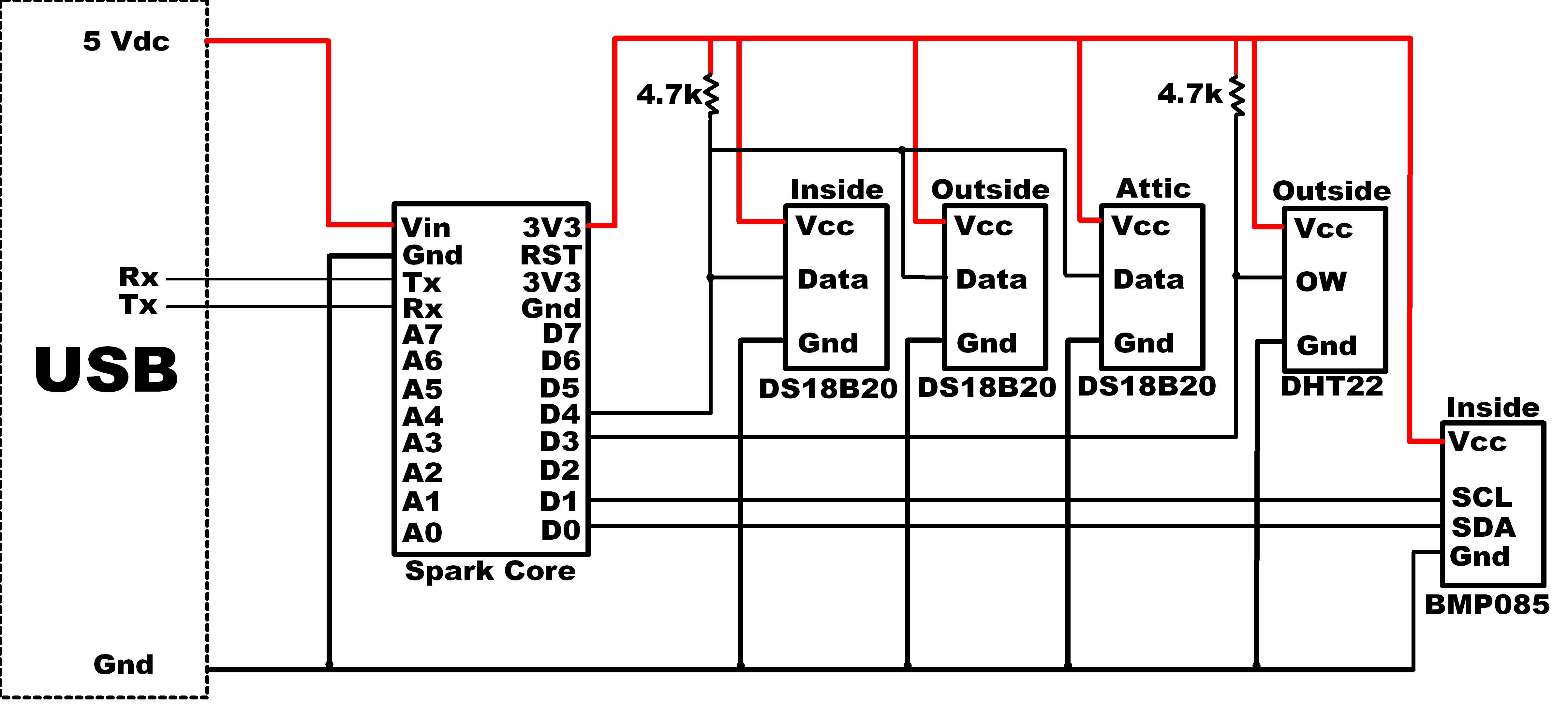
Current set-up using a Spark Core MPU
This interface only required 4 digital signals, those two pull-up resistors and a 3.3V power source. So you see that this is well within the capabilities of the ESP8266-12, which has 9 total (6 usable) general purpose digital IO pins exposed at the module interface.
My current configuration pulls data from the Spark Core. This is accomplished by sending http GET commands to retrieve the sensor values and storing them into a mySQL database once every hour by a scheduled CRON task on my web hosting platform. With the correct application loaded to the new module, a tweak to that script should be all that is necessary for the conversion to the ESP8266 data acquisition change.
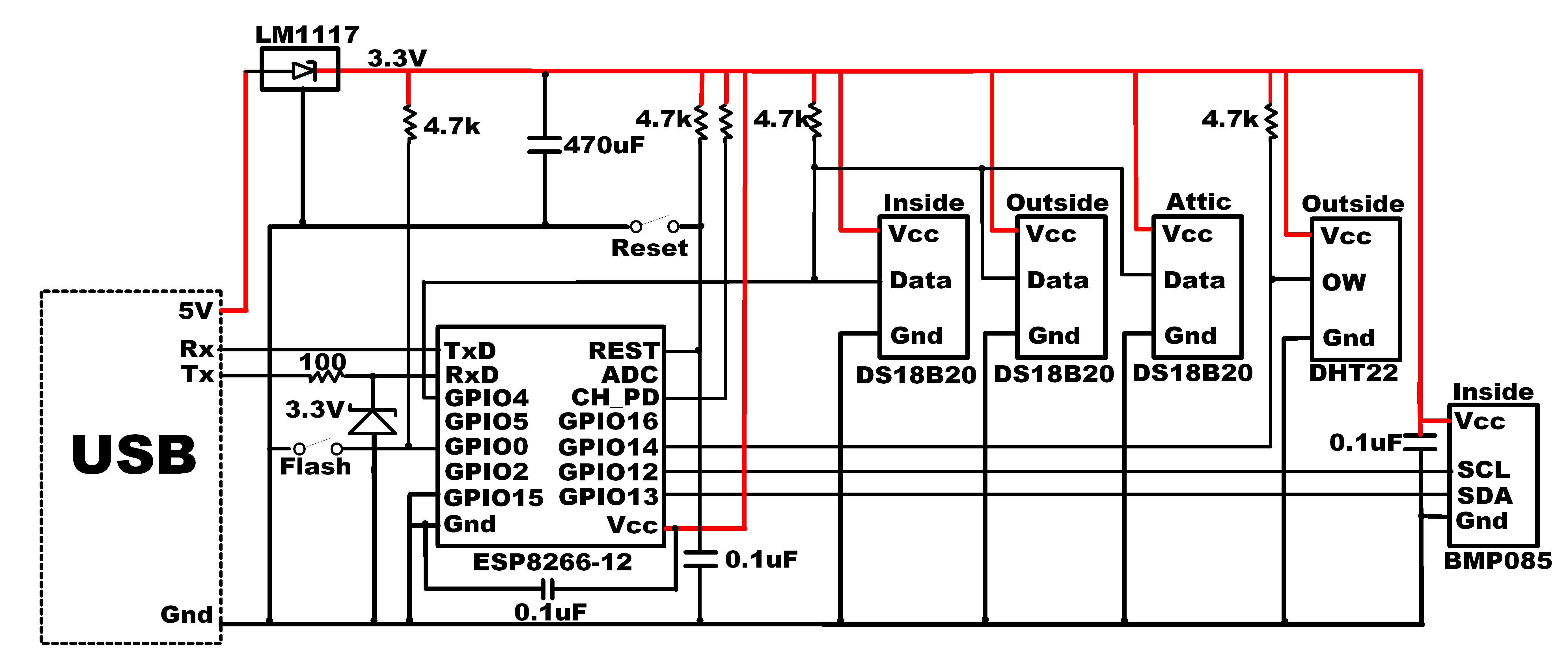
New set-up using an ESP8266 MPU
Just like the old set-up, four digital pins are used to interface with the 3 sensors.
Spark Core DIO vs ESP8266 GPIO usage
Initially, I had planned to use GPIO16 for the DS18B20 one-wire interface. That would have physically routed all the pins used for the sensors on one side of the ESP8266. This would not work, however, since GPIO16 can be used as an input or an output, but does not have the INPUT PULLUP, and OUTPUT_OPEN_DRAIN capability of the other GPIO pins. That feature is needed for the one-wire interface. But since the ESP8266-12 has additional digital pins, I simply changed the connection to use GPIO4 instead.
Note that the circuit has a 100 ohm series resistor with a 3.3V zener diode connected to the ESP8266 serial receive pin. This protects the module from potential damage from a 5V serial transmit source.
A LM1117 3.3V regulator is used to provide Vcc voltage. This device can provide up to 800ma of current, well above the ESP8266 needs. Using a USB to serial converter, the USB is connected to a 5V external supply (wall, battery, car adapter…) for the fielded ESP8266-12 circuit.
A large (470 uF) capacitor was placed across the 3.3V to stabilize the supply and minimize unwanted ESP8266 resets. An additional capacitor was connected to the reset signal, also to eliminate resets from spikes on the pin. Finally, for device decoupling, 0.1uF capacitors were placed across the ESP8266 and BMP085 Vcc to ground pins. These must be placed as close to the device pins as possible for maximum effectiveness.
Switches were added to support flashing and warm resets.
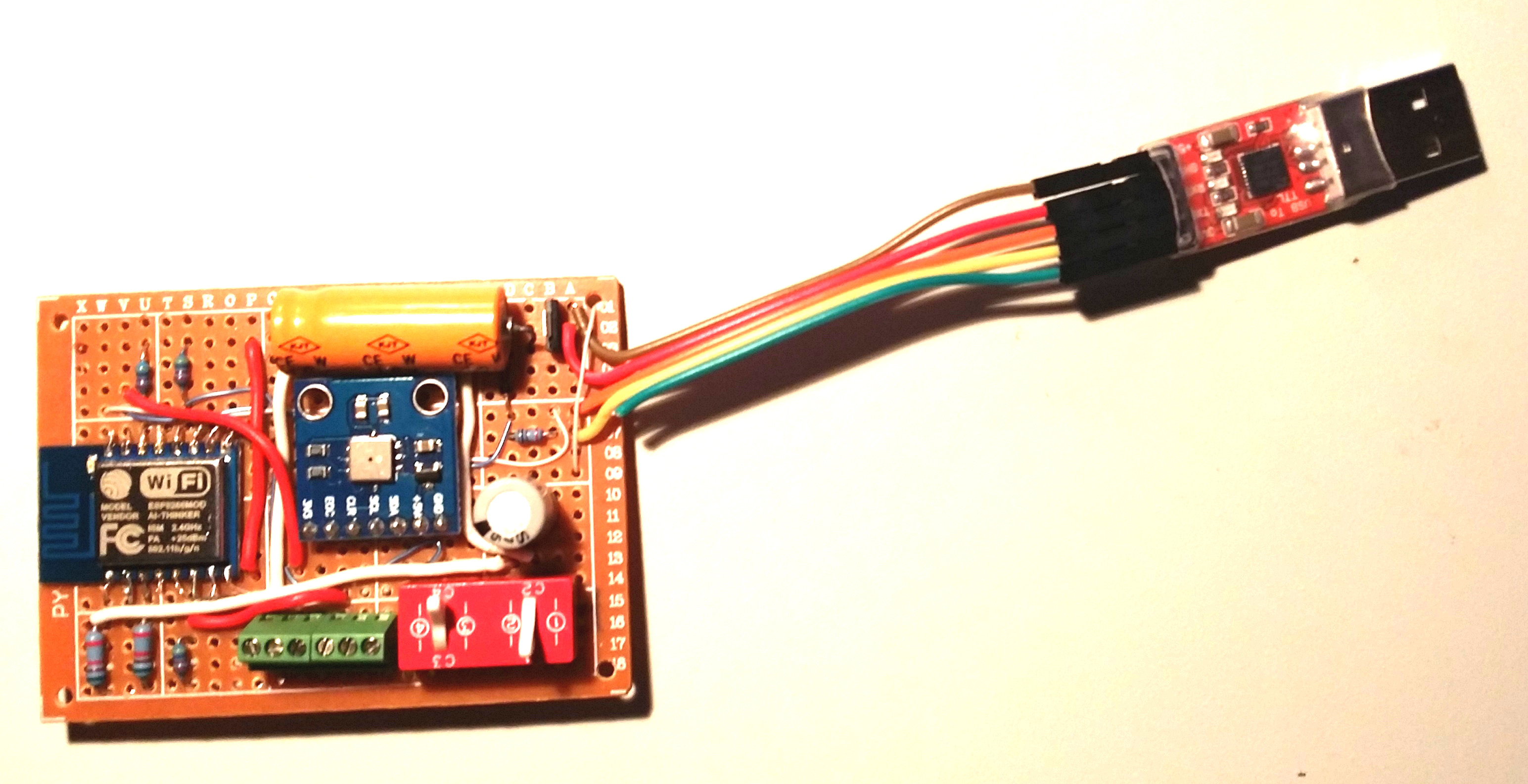
The circuit was assembled on a printed circuit board (PCB). I used 30 AWG wire to attach the 16 ESP8266-12 interface contacts to the PCB. 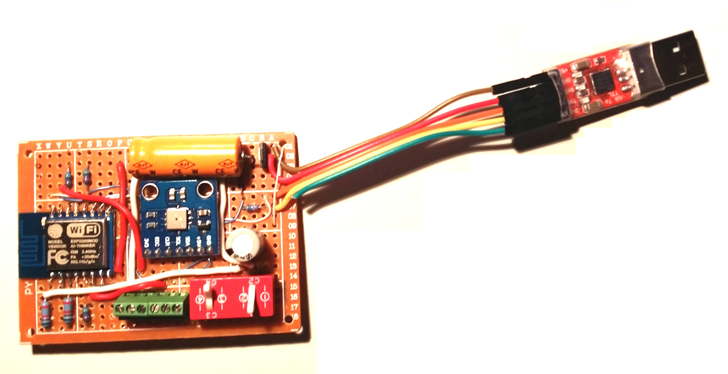 The Barometric Pressure/Temperature sensor (BMP085) was positioned in the center of the PCB. Interface to the external DS18B20 and DHT11 sensors are made at the green terminal block.
Note that the 3.3v signal (green wire) from the USB to serial adapter was clipped and not used. That source lacks the current capability needed for proper operation of the ESP8266.
Software Implementation
This was my first serious project using the ESP8266 after doing the basic “getting started” exercises. I started with nodeMCU and lua, then migrated to the SDK, and finalized the code using the Arduino IDE. This was not by choice but by necessity as there were insurmountable problems with lua and the SDK. And as of this post, there remains issues even with the Arduino IDE. But this article will remain focused on the porting solution. See the following posts related to issues I encountered during the development of the weather sensor porting firmware.
- 4 reasons I stopped using NodeMcu/Lua with the ESP8266
- Why I had to abandon the ESP8266 SDK – until a few things are corrected…
- Issues with the Arduino IDE for ESP8266
- 4 ways to eliminate ESP8266 resets
- What to do when you can no longer flash new ESP8266 firmware
Arduino IDE Web server
My code is based on the Arduino IDE example “WiFiWebServer”. After confirming the example code worked to turn an LED on & off from an external Internet connection, modifications were made to support the ported sensor requirements. The sketch and forked library files are accessible in GitHub here.
After many iterations, discovering what worked and what wouldn’t function, I came up with the following structure.
Included libraries:
#include <OneWire.h>
#include <ESP8266WiFi.h>
#include <Wire.h>
#include <DHT.h>
#include <Adafruit_BMP085.h>
#include <UtilityFunctions.h>
Everything worked “off-the-shelf” except for the BMP085 driver. The problem was that the “pow” function, used to calculate altitude, was not linked properly from the built-in IDE libraries. And if I tried to include “math.h”, which includes the “pow” function, the compiler failed with an out of memory error. I also attempted to implement a recursively called substitute function for the missing “pow”…unsuccessfully. I ended up removing the calls to the altitude function, and the need for the pow function. Not a big loss considering the fact that my sensors are positioned in a fixed location, the altitude will never change. My implementation of the pow function remains in the GitHub repository in the UtilityFunctions.c file in case someone may wish to explore this further.
Structure of the Arduino IDE loop()
Here are the key attributes of my code required for the most reliable operation:
1. WiFi connected check
First thing I added to the top of the sketches loop was a check to determine if the WiFi was still connected. This became necessary when I noticed that sometimes the connection was dropped, resulting in a non-responsive ESP8266 to”http GET” requests.
2. Busy flag
As you may well know, sending an “http GET” request by entering an URL into a web browser also creates several request for “favicon”. This sometimes created a problem when the ESP8266 sent it’s reply back to the browser and returned to the top of the loop. It appears that the reply, sent using “client.print(msg);” is a non-blocking call. That means the ESP8266 continues execution while the reply message send is in progress, This results in cases where the “favicon” request is received before the reply is sent. I figured this may be the cause for some of the ESP8266 lock-ups and resets I was experiencing. So I added a busy flag to block the processing of any new “http GET” requests until the current one is complete.
3. Sensor Reads
When all the sensor reads were attempted each iteration of the loop(), the ESP8266 kept resetting. I believe this was because the watchdog timer, set to about 5 seconds by default and does not appear to be controllable at this time, would timeout before the sensor reads were complete. Upon a timeout, the ESP8266 resets.
The solution was to limit the sensor reads to one read every 2.5 seconds. or a total of about 20 seconds to refresh all 8 sensors. This worked, and the resets no longer occurred endlessly.
4. Returns
The watchdog timeouts and subsequent resets occured frequently when all the steps in the sketch loop were executed every iteration. This was significantly reduced by returning from the loop after each significant event was processed.
Loop sequence returns:
- After Wifi connected, if needed
- If busy
- After a sensor is read
- If no client detected
- After client is killed
- If “favicon” request detected
5. Watchdog Timer Resets
The wdt_feed() should reset the watchdog timer. I have sprinkled some calls to wdt_feed() in my loop() after tasks that take some time to complete to avoid timeout resets.
6. Reply – json string encoding
The sensor data is returned as a json string for easy processing with a php or jquery script. I have attempted to add a few different json libraries to my Arduino IDE sketch, without success. They either would not compile or blew the memory space. So I ended up adding a simple json encoder to my sketch. It only supports key:value entries at the top level, but works flawlessly and uses an absolute minimum amount of memory. Check it out in my sketch.
7. Heartbeat Data logging
With all the problems I had with memory management and leaks using the nodeMCU/lua environment, for potential troubleshooting, I added a serial print to log 3 parameters:
- free heap
- processor time since last reset
- last sensor read
This was output every time a sensor was read (2.5 second intervals) and logged to a file using my terminal program. It has been very helpful in debugging problems. just like with lua and the SDK, I noticed the free heap drops for each consecutive “http GET”, lingering for a minute or so. This means in the current state of the ESP8266 hardware/software combination, you cannot continuously bang the unit with “http GET” requests. For applications that need to periodically extract information from the module over the network, a minimum of 1.5 minutes between requests is needed for a reliable, stable operation.
Conclusion
I can claim a success in the porting of the Spark Core Weather sensor code to the ESP8266 platform. All the same functionality worked within the ESP8266 constraints, with plenty of code space to spare.
And while I am still in the process of performing some “stress tests” to determine whether it is sufficiently robust to be relied upon for around the clock operation, it is looking good so far! After implementing both hardware and code measures to eliminate resets, I have not seen one yet. But this has only been about two non-stop days so far…
With the current level of interest, I expect the dependability of this device to improve with time. Higher quality flash chips, that reliably support more flash cycles than the current 25Q32 or 25Q40 chips shipped with new ESP8266 modules will be an essential component of the solution. And a more robust API to control the watchdog timer is also needed. Application control of the timeout period as well as a user defined timeout callback will go a long way in resolving the issue of unwanted resets.
Hope you find this information useful.
You may google “math-sll”. It separate floating point into High(integer)/Low(decimal) part and do only integer calculation without needing any math.h floating operation.
There are bugs in the original version of math-sll.h. Here is my modified and tested version with modification in sllatan() and _sllexp() functions.
http://pastebin.com/6VZ5fWPg
Speaking of Particle (f.k.a. Spark) Core, is there a way for ESP8266 to connect to the Spark Cloud or a local Spark Server (https://github.com/spark/spark-server) using the Spark Protocol? This way ESP8266 could be a drop-in replacement for the more expensive Particle Core/Photon.
I’ve heard of Digistump Oak, which is based on ESP8266 and claims to connect to Particle Cloud: https://www.kickstarter.com/projects/digistump/oak-by-digistump-wi-fi-for-all-things-arduino-comp/posts/1283926
Hi Dave,
Firstly thanks for sharing!
A quick bit of feedback for you, have you seen the ArduinoJson library on GitHub? It Might make the handling of the json output a little easier for you.
Great call on the favicon, the idea of adding in the busy check was ace, I’m nabbing that code right now 🙂 And… I also just learned about the yield() function. Who knew that existed!
You mention:
“Finally, for device decoupling, 0.1uF capacitors were placed across the ESP8266 and BMP085 Vcc to ground pins. These must be placed as close to the device pins as possible for maximum effectiveness.”
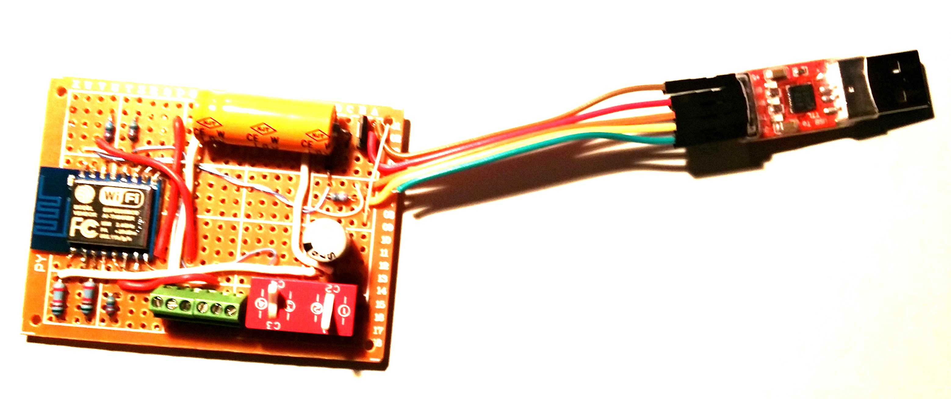
Yet I can’t see them in the photo you added, are they on the underside of the board?
Matt
Thanks for your feedback Matt,
I just had a quick look at that Weather Sensor circuit that has now been running for almost one year. The picture I had posted must have been before the decoupling capacitor was added.
I have seen the Arduinojson library but have not tested it yet. For more serious applications, I prefer to use the EspressIf SDK for code development. It has a built-in json library, among many other features that the Arduino IDE lacks. There is a bit more of a learning curve but in my opinion it unleashes the full potential of the ESP8266.
Oh, one more thing you might want to take note of, from my lessons learned. I am not sure of your setup, but if you are building up from a bare ESP8266 module, you might also consider using an adapter board. Very clean and reliable install, and they are cheap. Here is an old post about them.
Howdy,
Yep I have 3 esp8266’s I bought with the boards just like that and if I’m honest, I found them “intermittent” and not very reliable.
Note: None of them went to a soldered production, so could just be the breadboards I’m using (yep I have a good power supply etc).
I didn’t give up with the esp8266 though 🙂
As after using Arduino Uno’s & Pro Mini’s and becoming very frustrated with the lack of memory. It’s ni-on impossible to build a device that can be web controlled using JSON as data in/out. JSON is prefered as it means I can easily interface a PHP/MySQL/Bootstrap frontend.
So I grabbed one of the Wemos Mini D1 boards. They are sick!
Oh and one for you Dave, checkout Pushbullet.com
Inter-device notifications, so you can get notifications in your browser, on the pads and on the phone.
The library on github for esp8266/pushbullet is broken (I tried fixing it, C is not my native language so struggled, it’s the secure connection that is failing), so I manually created the POST/GET requests, they work amazingly well.
Someone at the front door?
Ding Dong on the phone, desktop, pads.
One of the alarms has gone off?
Alerts on all devices, home or away with the alert details.
And a morning wake up text message with a summary of the weather outside my door. “Today is -1 C with a humidity of 62%. All the alarms are set etc…”
All with oodles of device memory left over. I love these esp8266’s!
I’m going to have to donate all the Pro Mini boards I have here to a school of something, I have over dozen of them now idle :/
Matt
Hi.
Thank you for posting your experiences and let me know without wasting time.
As you discussed on your posts, I forgot NodeMCU and started to work on Arduino IDE, but because I didnt worked on this IDE, I couldnt build my project.
Arduino IDE by default need a Arduino Board to be defined, but I havent it, so, how can I define my ESP8266-12-E ?
Please explain how do I can build .bin files, it build .hex file instead.
And also explain that what is that firmware, is it like compiled “init.lua” in NodeMCU? or it is the complete firmware including Espressif SDK?
And where do I flash that binary? at 0x00000 or what?
thanks
best regards
MasooD
You should find the Arduino IDE very easy to work with when building sketches for an ESP8266-12. While there is a lot of information readily available on this subject, here are a few starting tips:
1. While the IDE changes periodically, I am currently using Arduino 1.6.9
2. After installing the IDE, you need to install the ESP board support package. This is a matter of selecting Tools->Board:…>Boards Manager… from the Menu. Scroll to the bottom and you should find the “esp8266 by ESP8266 Community” package. Select and install it.
3. Once installed, you might want to build and flash a simple LED blink or output something to the serial port, just to make sure everything is working.
4. I always select the “Board: Generic ESP8266 Module” as the board type (Tools->Board:). To compile, click on the left “Check” icon. To upload to your esp module, click on the second “Right Arrow” icon.
5. I have never used the compiled binary file stand-alone, as I either OTA program my ESP module or let the Arduino IDE take care of it. But if you want the binary, just selct Sketch->Export compiled Binary from the menu. The binary will be saved in your sketch folder.
6. After that, you just need to make sure the libraries you need for your project are included.
Regards,
Dave
Hey… Thanks for this article…
I have been banging my proverbial head against the wall with a NodeMCU ESP8226 12E dev kit (arduino ide) and trying to do very simple sensor reading loops and while everything technically works, the random resets are a nightmare with the Arduino IDE scripts… E.g. I can get it to reset just off a simple dht11 temp reading with a delay(5000) in the standard loop{}.
I am very interested to find out if your workarounds and further testing over the last 6 (or so) months has progressed and proven to be a stable solution?
typo ESP8266
Thanks for your comment Lance.
As I recall, the ESP8266 will timeout after 4-5 seconds without resetting the WDT. This means the loop() function needs to complete in less than 4 seconds or so. My approach has been to parse out projects with multiple sensor reading such that only one reading is performed each loop(). Each loop() then successively cycles through a sensor list, refreshing one reading each iteration.
i have to admit, I have not been actively researching solutions to the long-term stability issue, but I can tell you that my continuously running project that monitors 3 temperature sensors as well as humidity and barometric pressure has recorded the longest time between resets as 49 days! I have not heard of anyone getting better results. But still, I need to record more information to determine what caused the system to reset after 49 days.
Here is my ThingSpeak public channel that continuously refreshes the results: https://thingspeak.com/channels/33251
The ESP8266 circuit, along with the internet cable-model are on a UPS system to eliminate poser outage disruptions.
My next step in improving the reliability will be to build a dual-redundant system, using two ESP8266 modules. The thought is that it is highly unlikely that two modules will reset at the same time. Once the reset ESP8266 become back on-line (in a matter of a few seconds after the reset event), the two modules will re-sync with an identical data set. The test will be to use a deterministic data refresh rate and verify not loss of data over time. I am hopeful that this setup will be able to run indefinitely without loss of data.