Want More Analog Inputs?
Do you have a project needing more than one analog input? If your using an ESP8266, that would seem to be a problem as it only offers a single input. Before you commit to using an Arduino, Spark Core, Raspberry PI or other higher priced micro-controller, one with multiple analog inputs, consider this…
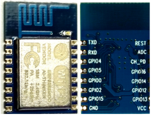
Adding an 8-1 multiplexer chip to your ESP8266-07 or -12 circuit can expand your system capability from one to eight analog inputs. I recently tested this out, using a 74HC4051 CMOS analog multiplexer component I got from an AliExpress supplier.
The cost?
$2.19 for 10 chips, or $0.22 per chip.
They are available in a 16-pin DIP package with 2.54 pitch for easy use with a solder-less breadboard.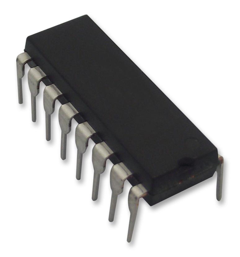 So what’s the downside? Well, selecting one of the 8 analog inputs will require 3 GPIO pins. For many applications, that should not pose a problem when using the ESP8266-07 or -12. These versions have 7 easily accessible GPIO pins available, leaving you with 4 GPIO pins for any digital input or output requirement after adding the 8 analog inputs.
Here is the circuit I used to test this configuration:
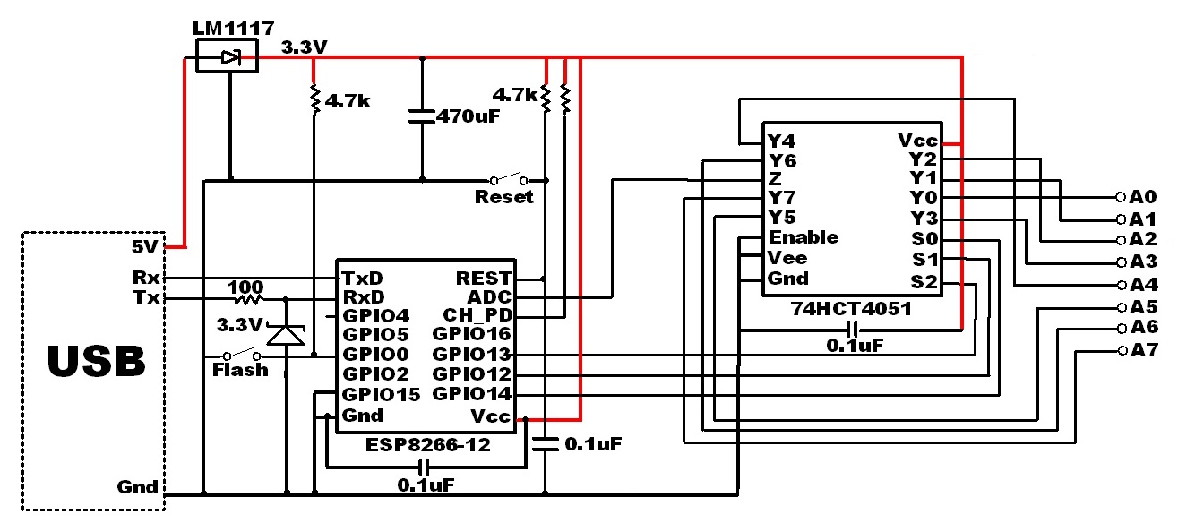
The left side of this drawing is the standard circuit I have been using for all of my ESP8266 projects. A typical USB to serial adapter is used when developing and flashing the circuit. When deployed, I use a USB plug with a wall adapter to provide a 5V source, without the Tx/Rx signals.
The analog multiplexer is controlled by 3 GPIO pins; 14,12 and 13. Setting the states of these 3 digital outputs determine which analog input will be measured.
The sketch used to test this circuit was developed using the ESP8266 Arduino IDE.
The serial output loops through each analog input, setting the multiplexer and reading an input every 2.5 seconds. The sketch also behaves as a web server. All 8 analog values can be retrieved in a single JSON string returned from an http GET request.
ESP8266 ADC Performance Evaluation
Using this circuit and software, I proceeded to collect some data to characterize the ESP8266 analog input range. First, the multiplexer selector was verified by connecting each input to ground and verifying the Analog count returned was 0. Likewise, each input was connected to 3.3V with a reading of 1024 returned when reading the ESP8266 ADC pin.
All good so far…
Then I connected the A0 input to a variable resistor to vary the input voltage voltage.
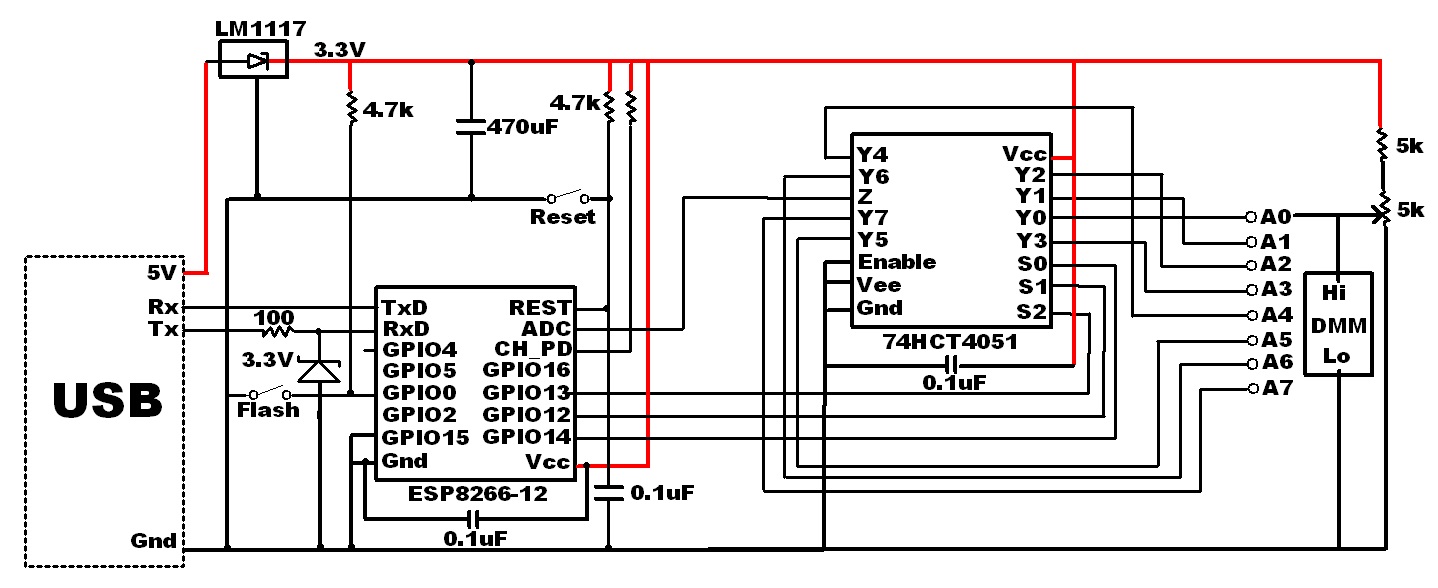
At the same time, an external Digital Multimeter (DMM) was used to monitor the voltage applied to the ESP ADC input via the multiplexer. For each voltage setting, I recorded the DMM reading and the ADC count returned from the ESP8266. It would have been great to have a calibrated bus controlled DMM to automate this process, but for the purpose of this DIY home project, I simply entered the values into an excel spreadsheet manually.
Thirty-seven voltage settings were applied in the range between 0.2V and 1.2V. Any voltage below 0.2V returned a 0 bit count while voltages above 1.2V returned 1024. I observed approximately 10 values returned from the ESP8266 for each voltage applied and recorded the high and low bit count readings for these measurements. The average of the high and low reading was then used to chart the results.
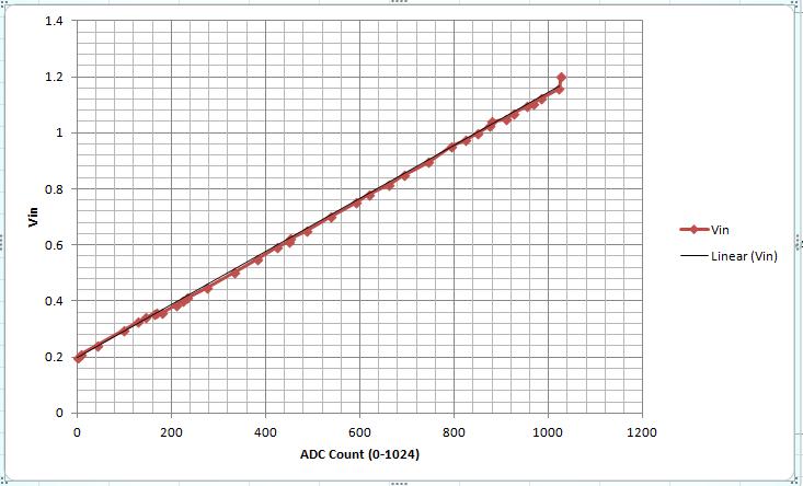
As you can see, the results were reasonably linear. But there is compression at the voltage extremes. For practical use, I would not use the non-linear ends, limiting the voltage swing from 0.25 to 1.15 V, a 0.9 V range.
The data collected can be reduced to a “best fit” equation. This would provide a method of converting the raw ADC value count to a voltage. Ideally, a data point should be collected for each ADC count value. The equipment I used for this exercise was not calibrated or accurate enough to do this. Given these uncertainties in my test setup, I am not sure if the variances I observed for consecutive readings…and they did vary somewhat…was result of the input voltage source or the ESP8266 ADC.
Still…with the data I had collected, the formula was determined to be:
Vain = (0.94* ADCcount + 200) mV
The slope was determined by dividing the voltage difference by the ADC count difference at each end of the voltage range. And 200 mV, the intercept, is the voltage when the ADC started reporting 0 for the count.
While there does not appear to be a definitive specification, this is consistent with what I have read regarding the ESP8266. The 10-bit ADC resolution is supposed to be approximately 1 mV with a 1 V range.
Resolving Sensor Incompatibilities
So what can you do if your sensor range is outside the ESP8266 0.2 to 1.2 V window?
Scaling of course.
This can be accomplished passively, using a resistor divider, or actively, with the addition of an op-amp. The interface of choice would be an active op-amp based circuit.
For example, suppose your sensor has a 0-5V range. This would need to be scaled to fit in the ESP8266 0.2 to 1.2 V input range. Obviously, resolution will be compromised as we go from a larger range to a smaller one, but it can be done. And with a single power supply.
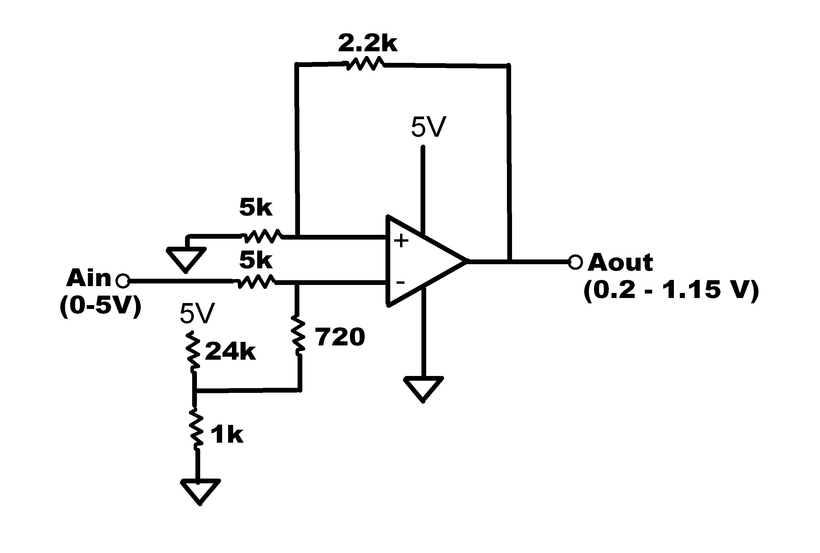
Resistor values calculated here. The 24K/1K resistor divider supplies the 0.2V offset with the gain set for the 1.15 V output with a 5V maximum input applied. This circuit would need to be modified for your specific sensor voltage range.
In summary
So there you have it. Eight analog inputs measured using a single ESP8266 SoC. Possible simply by adding a 22 cent chip.
And I got to mention one more option. Just in case you want even more…
A 16 channel version of the multiplexer is also available (74HCT4067). That’s a whole lot of analog!
I hope you find this information useful.
Social tagging: ESP8266 > Expand ESP8266 capability > More ESP8266 Analog Inputs
Hi,
Nice work!
Can you provide the used header files? And on which version of Arduino IDE did you compile?
Best Regards,
Mr. Breaker
The sketch was compiled using the Arduino IDE Version 1.6.1. It should also compile with the latest version.
I have added the header and source files for the UtilityFunctions library to the Github repository.
I also deleted the following extraneous header files from the sketch; these were left-overs from another project:
DHT.h
Adafruit_BMP085.h
Wire.h
OneWire.h
The ESP8266WiFi.h file is included with the Arduino IDE.
And finally, the user_interface.h file is included with the Espressif SDK. I am currently using SDK version 1.0.1 dated 24 April 2015. There are later revisions, but I have had issues with them. The 24 April version is the latest version that i have found to be reliable and stable.
i build the adc but i dont success to read the data from the nodemcu
The circuit was tested using the Arduino IDE. The sketch link is provided in the post (click on “sketch”).
I am not a big fan of lua scripts and have not created one for this circuit. If you are determined to use lua, send me your script and I would be happy to review it and provide some feedback.
I highly recommend you use the Arduino IDE or EspressIf SDK for your ESP8266 code development. You surely would be pleased with the superior results vs NodeMCU lua.
Is there any way to send the data through MQTT?
Of course your ESP8266 Arduino IDE code can interface with a MQTT broker. There are many code examples on-line Here is one:
https://gist.github.com/igrr/7f7e7973366fc01d6393
Here is my recent post which includes an ESP8266 MQTT example sketch. http://wp.me/p5NRQ8-i5
can you please put the pure code to read all sensors without the json stuff? thank you very much.
Thanks for your comment. While it is not clear exactly what you are seeking, the sketch had been revised to return, on request, the raw analog value of a single selected channel. You should be able to customize the sketch to your exact requirements from what is in the revised sketch. It is on GitHub at:
https://github.com/internetofhomethings/ESP8266AnalogMux
In the sketch provided, IP = 192.168.0.132 and Port = 9701. You can change these to your needs in the sketch. With this, you can now retrieve the raw analog value (0-1023) for each of the 8 individual inputs (0-7), without any JSON:
http://192.168.0.132:9701/ain/0
http://192.168.0.132:9701/ain/1
http://192.168.0.132:9701/ain/2
http://192.168.0.132:9701/ain/3
http://192.168.0.132:9701/ain/4
http://192.168.0.132:9701/ain/5
http://192.168.0.132:9701/ain/6
http://192.168.0.132:9701/ain/7
Hope you find this sketch useful.
By the way, I have seen that error message before. It occured in my case when my mySQL server was not running on my host. You might want to check that possibility.
Hi,
there is an error in the picture “ESP8266-schematic-amux-1024×477” GPIO14 and GPIO13 has to be swapped.
Regards, Andy
Thanks for pointing out the error in the schematic Andy. I hope it did not through off your efforts too much. The schematics have been updated.
Hi,
Nice work!
In the schematic the 74HCT4051 is drawn. Please keep in mind that the HCT types are out of range for the Vcc 3,3 V. (May be they can work, but they must not) Instead you can use the HC types.
Hi,
Why did you decide to go with 470uF capacitor for the output on the regulator?
The exact value is not critical. I bought 100 470uF capacitors in a small package from China for a couple of USD to use for this purpose. Larger capacitors will provide more smoothing and transient protection, but generally, the larger the capacity, the larger the size of the device. 470uF was a good trade-off at a very low cost. If you have a random selection of capacitors available, I would not use one less than 100uF for this purpose.
Hi,
Could you measure all the analog inputs at the same time?
Regards
There is only 1 analog input to the ESP8266. This low-cost solution selects one of the amux inputs at a time and measures it.
An possible alternate low-cost solution would be to tether an Arduino with 8 analog inputs to an ESP8266. Here is my implementation of this option: http://internetofhomethings.com/homethings/?p=1277
This is simply great! Thanks a ton! I cannot wait to get the MUX and start working on this. Your code is overly functional, but very very helpful. Just have to scale it back a bit. Quick question. Do you have any idea on which 74HC4051 to buy? I've seen them listed as 74HC4051, 74HC4051d, 74HC4051e, and some with more letters. Is there a difference? Again, seriously appreciate this tutorial!
I bought a lot of 10 of these analog mux chips from Aliexpress in 2015 for 2.19 USD. On one of the chips it reads "74HC4051N". The supplier I used no longer offers them but here is an equivalent to the ones I got:
https://www.aliexpress.com/item/10pcs-free-shipping-74HC4051N-74HC4051-SN74HC4051N-DIP-16-Multiplexer-Switch-ICs-8-CHANNEL-ANALOG-MUX-DEMUX/32416713940.html?spm=2114.01010208.3.2.iyICV3&ws_ab_test=searchweb0_0,searchweb201602_4_10065_10068_10000032_119_10000025_10000029_430_10000028_10060_10062_10056_10055_10000062_10054_10059_10099_10000022_10000012_10103_10000015_10102_10096_10000018_10000019_10000056_10000059_10052_10053_10107_10050_10106_10051_10000053_10000007_10000050_10084_10118_10083_10000047_10080_10082_10081_10110_10111_10112_10113_10114_10115_10000041_10000044_10078_10079_10000038_429_10073_10000035_10121,searchweb201603_2,afswitch_4,single_sort_1_default&btsid=5e46d708-bd41-43f3-9aba-923e7397ce2d
The "slow boat from China" takes about 6 weeks from time of order to the time it arrives in your postbox.
Hi, there is a possibility to make also different trades. Not only 3 digital outputs for 8 analog inputs.. You can also get 4 analogs for 2 GPIO or 2 analog for 1 GPIO.
Just put the most significant address inputs of IO to ground and drive with GPIOs only one or two other 🙂
Just idea, which could be usefull for someone.. I dont need 8 inputs.. i need more GPIOs 🙂 so maybe it will help to someone
You don't need any of the esp8266 outputs if you 'feed' the 74HC4051 pins HI/LO manually using physical switches (:
The link you provided did not work. It returned “could not connect to database”. It had to be removed from your comment. Please fix the link, perhaps it only works when connected to your LAN, and reply here if you would like to share something regarding extra channels using a MUX IC. Thanks!