
Even though I live alone, there are 4 TVs spread around my house. And since only 1 set is needed at a time, only one DVR box is needed. So I used a 1-4 HDMI splitter/driver to distribute the signal from the one box to the 4 TVs. Using the attic pathway, direct connections were made to each of the sets. It was pleasing to see that the active HDMI splitter could drive the remote TVs without any pixelation or frame freezes. The furthest HDMI cable required 100 feet. But here was the problem…
The remote would only work when pointed directly at the DVR. Sure, my Att-Uverse service includes a free smartphone App to use as a remote control for the other TVs. But that experience is not the same as using the physical remote that you get with the DVR.
I did have one IR transmitter/receiver pair that I purchased off-the-shelf. Works great! But at nearly $50, it just seemed a bit cost prohibitive to add additional pairs for the other 2 sets. So that got me thinking…
Hmmm. A micro-controller would work. But the relatively high cost of an Arduino, Raspberry Pi or Particle WIFI enabled system was unappealing. So this looked like another opportunity to deploy the low cost ESP8266 as a solution. Here is what I came up with…
IR Remote Solution using ESP8266
Initially, I wanted a system that used an ESP8266 positioned locally at the TV set, one setup for each television. The system would use an IR sensor to read the remote code to determine which button was pressed. Then, the ESP8266 code would take advantage of the AT&T U-verse® Enabled SDK. This interface would, based on the button pressed, send commands to the DVR, over an internet connection.
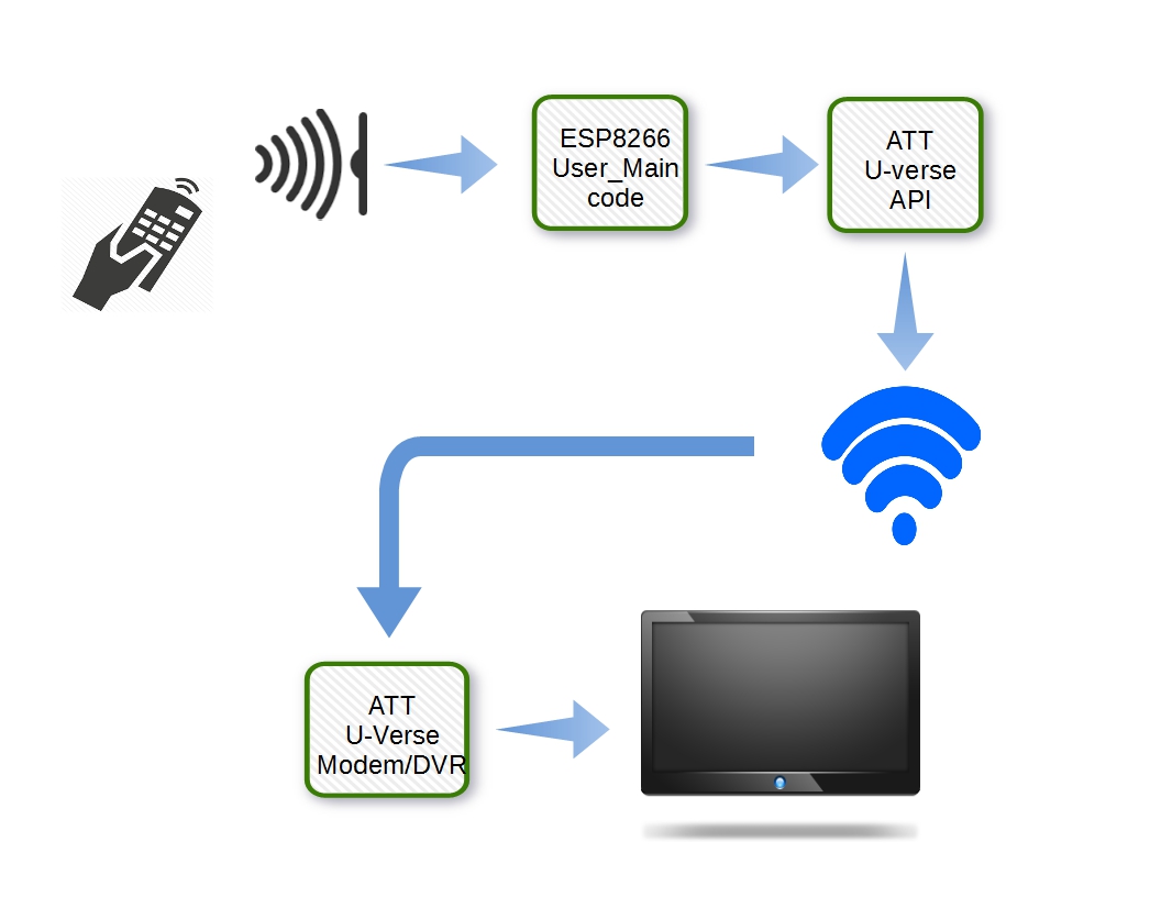
But there was a problem…
You see, the SDK only supports mobile apps using iOS or Android platforms. While I believe there is a way to port the java-based SDK to the ESP8266 embedded platform, it is not an endeavor I wish to pursue at this time. That’s the problem-it will take too much time. I was hoping that ATT would provide the solution.
So I sent a request to ATT to provide an SDK suitable for micro-controller use. We shall see what they have to say about that. You never know unless you ask…
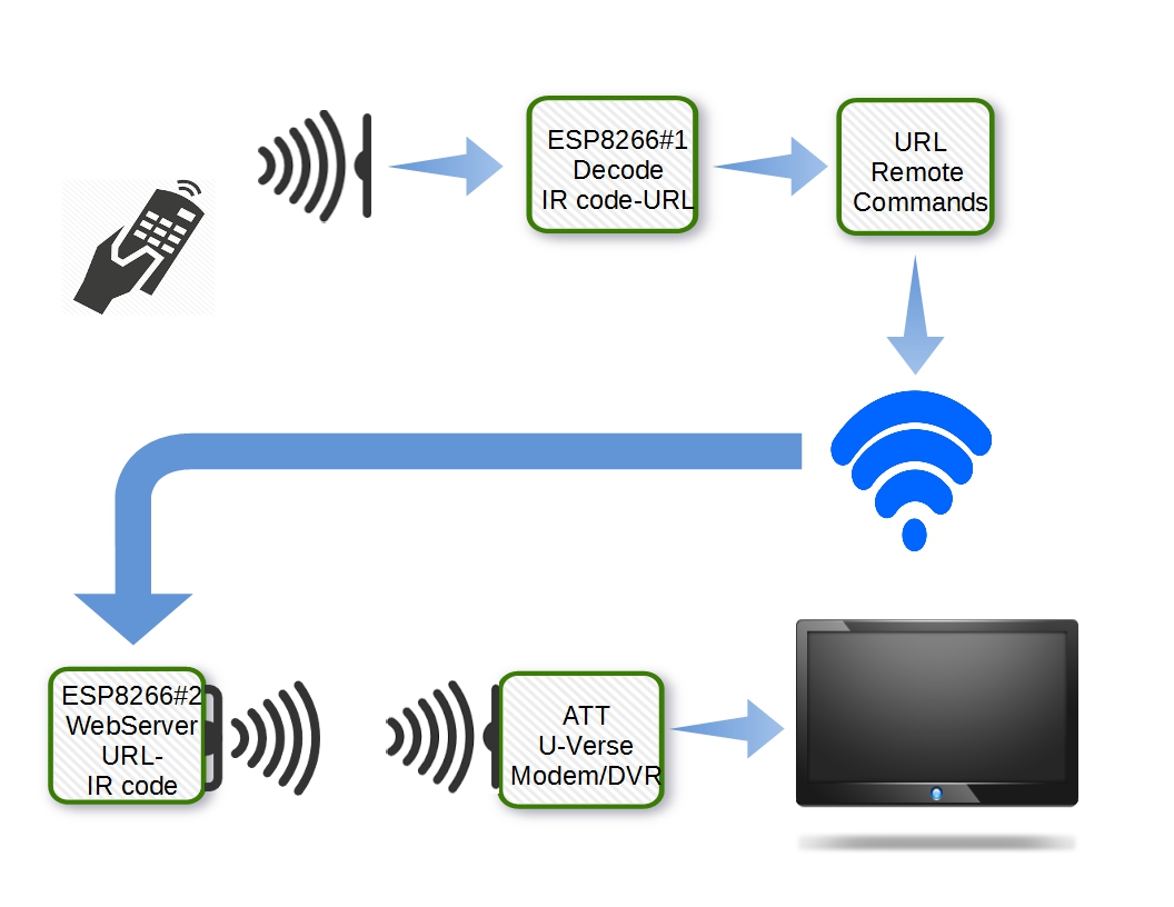
Plan B: Adding another ESP8266 at the DVR
In order to move forward with this project, an alternate approach was needed. One that could be totally controlled within the framework of a micro-controller system. Without the need for a 3rd-party API.
I really just came up with a tweak of the original concept. Instead of using the ATT SDK, the IR commands would be sent to the second ESP8266 setup, using an web-server client command. This added unit, functioning as a web server, would be responsible for receiving the remote control commands and then transmitting the corresponding IR code to the DVR, using an IR Diode similar to the type found in remote controllers.
ESP8266 IR Remote Hardware Configuration
Here is the schematic of the circuit I used to check out the ESP8266 IR Send/Receive software.
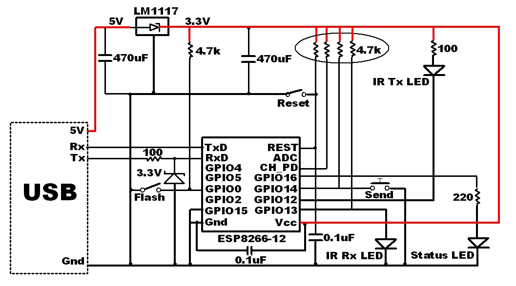
The left side of the ESP8266 is the standard design I use for all projects. It has proven to be very stable, with hundreds of flash cycles completed successfully and no unintended resets during operation.
Three LEDs are used in the circuit:
- Status LED – A standard LED used to provide visual feedback.
- IR Tx LED – Sends IR data to the DVR
- IR Rx LED – Receives IR data from the DVR remote control.
In addition, a simple push-button switch is used to send the last code saved to the DVR.
This circuit contains all the hardware needed for both ESP8266#1 and ESP8266#2. As you can see, there are only a few components needed. It is probably wise to stick with this single hardware configuration for both ESP8266 setups.
However, once tested and all the remote codes have been “learned” and saved, the two ESP8266 systems could be optimized as follows.
ESP8266#1:
IR Transmit LED, Send switch and Status LED could be removed. The only thing needed is the receive IR. Remember, a separate ESP8266#1 circuit can be used for each TV you wish to control with a single DVR box.
ESP8266#2:
IR Receive LED, Send switch and Status LED could be removed. The only thing needed is the Tx IR. Only one of these circuits will be needed, regardless of how many remote TVs are used.
IR Remote Control Signals
There are many great articles that provide details on how IR signals are generated, transmitted, received and decoded. Instead of repeating, here are a few references for further reading, if you want to know more. This post will concentrate on an ESP8266 IR remote solution.
ESP8266 IR Test Software
My initial idea was to port an existing IRremote library from the proven Arduino platform to the ESP8266. The obvious choice was the “RobotRemote” library provided as a standard Arduino IDE library. But the differences in the ESP8266 hardware from the Arduino ATmega chip made the porting difficult.
Even after resolving all the compile errors, I could not complete a successful link to all the libraries. Eventually I ended up abandoning the Arduino IDE platform for this project in favor of the EspressIF SDK.
But this decision came with additional challenges as the SDK does not easily support c++ class libraries. Like the “RobotRemote” library. This issue was overcome by decomposing the class structure into separate ANSI C functions.
But there was more to deal with…
Remote IR Signal Generation
The Arduino library relies on the PWM capability to generate the standard 38 kHz IR modulation frequency. Unfortunately, the ESP8266 PWM API only supports up to 100 Hz, a far cry from the needed bandwidth.
Fortunately, there is a way around this ESP8266 constraint. The trick is to create the 38 kHz modulation by simply toggling a digital output; logic 1 and logic 0. The duration of these pulses determine the command sent to the remote receiver. But how do we generate 38 kHz pulses?
Simple…
Using the ESP8266 micro-second delay statement “os_delay_us(us)”, we can create a 38 kHz pulse train. Each pulse period is 1/38000 seconds (26.3 us) long. Rounding that off to 26 us, the modulation frequency is easily achieved with:
  loops = time/26;                    // "time" units are microseconds
  if(loops==0) loops=1;
  for (i=0;i<loops;i++) {
          gpio_write(IR_SEND_PIN, 0); //Set GPIO12 LO -> IR On
	  os_delay_us(13);  //1M/38K/2
	  gpio_write(IR_SEND_PIN, 1); //Set GPIO12 HI -> IR Off
	  os_delay_us(13);  //1M/38K/2
  }
Here, each iteration of the loops generates one 38kHz pulse (26 us). The number of pulses (loops) is determined by the desired number of microseconds.
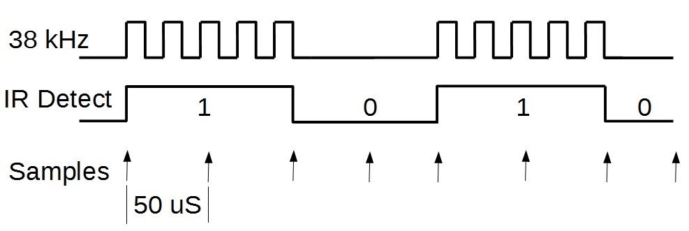
Remote IR Signal Detection
In addition to generating IR codes, we must also be able to detect and decode IR signals received from a remote. That requires a sampling of the state of the IR detector diode (is it HI or LO). A 50 us timer callback function is implemented for this purpose, which is the same 20 kHz sampling frequency used by the original Arduino RobotRemote library. Since the 38 kHz modulation is removed by the IR detector, the remaining signal content (set of ones and zeroes) change at a lower rate. As result, the 50 us sample rate is adequate to accurately decode the incoming IR code.
Initial Implementation
My initial implementation provides a framework upon which to build an ESP8266 based IR remote application. It is not meant to be a complete application, merely a platform to prove the concept. From this structure, it will be possible to easily adapt the code for your specific needs. I plan to follow-up this post with my final design.
From the current structure, it will be a straightforward task to record and store all the IR remote codes for subsequent replay, on demand, by the ESP8266#2 web server.
Here is what this project currently does:
- With the push-button in the schematic open, the IR detector is monitored every 50 us for the presence of an IR code. Every time a logic state is detected on this sensor, the LED connected to GPIO16 is blinked. In addition, the received code is sent to the serial port. Once a valid code is detected, it is stored for playback, on-demand, by the IR emitter diode.
- When the push-button in the schematic is pressed, the IR detection process is stopped and the last IR code store is transmitted. The code is repeated every 0.5 seconds as long as the button is pressed. IR detector sampling will resume once the button is no longer closed.
The code for this project is on Github here.
What to do next
Note that the IR codes sent to the serial output can be saved using any terminal program that saves the output to a file. By sequentially walking through each key on a remote, a map of button pressed to IR code can be created. This map will have 2 purposes in the final design:
- ESP8266#1: The received code can be “looked up” in the map, to determine which remote key was pressed.
- ESP8266#2: Once the Web server receives a command to send a key code, the map will identify the code to send for that key.
The one shortcoming I have observed with this initial design is the limited range for both sending and receiving IR signals. Currently, the signal fades and starts to drop out beyond only 1 meter. This has one of two possible causes, which I intend to investigate.
Either the signal intensity is inadequate or the signal MARK/SPACE timing is off. We shall see.
I blew up a couple of IR Emitter Diodes using a transistor to increase the LED intensity. As results, a more thorough evaluation is needed before I proceed with additional modifications. I will provide additional information when a better solution is reached.
Conclusions
The project presented here provides a solid foundation for any ESP8266 application using IR communication. This design uses the EspressIf SDK but could most likely be adapted to work with the Arduino IDE. So that others may benefit, please post your work in the comments below if anyone has ported this to the ESP8266 Arduino IDE platform.
Hope you find this information useful…
Social tagging: ESP8266 EspressIf SDK IR Remote > ESP8266 IR Remote > IR Remote
Excellent post. IR receive have stable values for mark and space? I have tested some libraries for ESP8266, but mark e space values are variables. Example: Sony Code with space de 600us have values between 350 e 700us. Do you have this problem?
Thanks for your feedback. I am out in the field this week and will run some tests when I return to assess your findings. I’ll let you know what I discover.
Hi Leandro,
My only Sony Device is a Blu-Ray player, Model BDP-BX18. But I believe the remotes from Sony over the past few years for TVs and Blu-Ray are similar or identical. Using the EspressIf SDK ESP8266 code from this post, I tested the “OK” and numeric keys “3”, “4” and “5”. The Received mark and space patterns for each of these keys were unique as one would expect. I captured the decoded pattern from the ESP8266 serial port 10 times for each key. The pattern decoded was amazingly consistent. The range for each mark or space in the each sequence, when they were not the same, only varied by 50 us, which is our sample rate. That should be expected.
Since you are experiencing much more variation, something else must be going on. Here is what I would consider:
1. You mentioned that you have “tested some libraries for ESP8266”. Were you also observing the varying decode values from the library included in this post? I am not seeing the decode variations you mentioned.
2. The decoded value is displayed left to right starting with a mark value. Every Sony Code I decoded starts and ends with a mark, with spaces between each mark. Each code has 21 marks and 20 spaces. So each time the remote is decoded by the ESP8266, we expect the first mark to match, the first space to match, etc. Are you seeing variations in the first mark, for example?
3. Is there anything else running in your ESP8266 firmware that would impact it’s ability to decode the IR signal received in the 50 us timer callback? It would be wise to minimize any other activity while the ESP8266 is decoding an incoming signal.
I also ran some tests with my ATT U-Verse remote. The received patterns were also very consistent, with only a 50 us variation from max to min value for each mark/space.
You might also try testing for decode variation with a different remote to assess whether it is in the decode logic or isolated to the Sony Remote you are using.
Good luck…
Hi, you mentioned that you could get a range of only about a meter while receiving and sending; the reception range would be highly enhanced if you use a 3 pin tsop IR module, the only negative being since it also de-modulates the signal, you would not be able to determine the carrier frequency. At the transmission end, are you sure your data is being modulated at the required frequency?
Best regards,
Anand Dhuru
Thanks for the tip Anand.
I am definitely going to try using a tsop. Do you have a model to recommend? I noticed several offered. Wondering if there is a preferred one.
Since the ESP simulates 38 khz with a 26us period, the carrier is slightly higher (38.4. Khz). That is the best we can do with this microcontroller.
Great info. Some thoughts:
Stronger IR transmission usually uses a transistor of some sort gating a higher power IR LED than can be directly driven by a uC port.
As I understand it, using the OS delay is guaranteed not to return sooner than the time requested, but it could be later. And that's probably OK in this application, since it's standard to send the codes more than once, so an occassional stretched time between transition may not matter. Or perhaps such "timing glitches" affect your range or reliability.
What part are you using for your "IR Receiver diode"? It's shown in your circuit as a simple two pin diode (pulled high), but your diagram shows not the 38 KHz carrier being output, but instead a decoded signal exactly like a TSOP receiver produces.
You are correct. The timing diagram shows the diode output (without the 38khz carrier. The IR receiver diode used was a cheacomponent I picked up at the local Radio Shack before they went out of business.
https://www.radioshack.com/products/radioshack-infrared-led-emitter-and-detector?gclid=CjwKEAjw2qzHBRChloWxgoXDpyASJAB01Io0tdn976QKyw-83MsLA2_Ev8c_O20b57oqs09KW6TwlBoC_Wfw_wcB
I should have provided a parts list with this post.
Novice Here.. Hardly ever held the soldering iron in my hand. So please let me know if I make sense:
Idea 1) A bit low tech. Instead of a reciever at every TV, what If you could integrate the ESP8266 into the remote? Or strap it to the remote(if you don't want to spoil the service provider provided remote)?
Idea 2) Really low tech.
I was wondering .. What if – you have an IR sensor, a long wire from one tv to the DVR, an amplifying circquit, and an IR LED at the other end? In short, an IR "Intercom". Would it work?
Note: The second idea would still require a sensor at every TV
Both your ideas would work. The seconds one is a wired solution. That could get messy with a large home.
Your first idea is a good one. Tapping into the remote battery to supply the ESP might work, but it is typically 2 AA or AAA batteries, which is only 3V and the ESP uses 3.3V. It might work with the lower voltage, but also could introduce instabilities.
Thanks for the reply.
What about
1) A step-up like this one http://www.instructables.com/id/Adjustable-Voltage-Step-up-07-55V-to-27-55V/
or
2) 3 x1.5v button cells = 4.5 volts?
it's hard to decode long ir codes with this. use irdevkit.com. easy