Archives for September 2015

How To Unbrick FTDI Based Arduino Nano

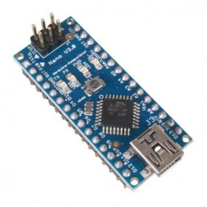
nano_

Do you have an Arduino Nano that is non-operational? Failing to upload sketches? Behaving basically as a dead device. Non-responsive. Essentially a brick.

My Nano started behaving that way when I pulled it off the shelf to help someone with a project. This became another problem to be solved. It had to be corrected before using the device again.

So I searched for an answer on-line. It soon became clear that the root of the problem was the FTDI USB-to-serial conversion chip. Everyone was offering the same solution.

But, unfortunately, none of the information I found worked for my unique case. You see, my first attempt at solving this problem, in reality, made things worse. The contents of the FTDI flash had been altered. Making it unrecognizable and inaccessible.  I had to come up with an  answer to that issue first before addressing problem most users had been experiencing.

After much research and failed attempts, I have now come up with the complete solution. You may not need to do all these steps, unless you corrupted the nano’s EEPROM as I did.

Problem Discovery

After several unsuccessful attempts at uploading a compiled sketch, I had a closer look. The first thing to do was to monitor the devices serial port. This interface (USB at my PC) was spewing  “NOT GENUINE DEVICE FOUND!” endlessly at 115200 baud.

After some thought, I concluded that somehow the device claimed to be “Arduino-compatible” was in-fact, counterfeit. And somehow, the driver used to communicate with it’s FTDI interface chip knew it. Blocking it’s normal operation, replacing it with the message I was observing.

As it turns out, this “blocking message” was placed in the driver by the OEM, FTDI. Since everything worked initially, going back about a year and a half, but not now, a driver update had to be responsible for this new, unwanted behavior.

But what can be done to fix it?

From Bad to Worse

From what I had read, the problem was that the “updated” driver had a method to detect “non-genuine” chips. In those cases, the USB device descriptor ProductID (PID) was altered from 6001 to 0000.

The trick was to change the PID back to 6001. Fortunately, FTDI provides a utility to do just that. It is called FT_PROG, available here.

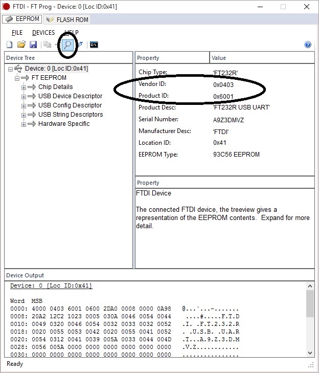
Changing the PID was easy with this program. Just start it with the nano plugged in, click on the scan icon, and your nano device settings are displayed. Just play with this program a bit and you will figure out how to change the Product ID.

FT_PROG

Yet after correcting my Product ID, the problem did not go away. I carefully looked at the instructions in an article with the “solution” and found one thing missing…

The Vendor ID was set to 0401 in the article and mine was 0403.

So I changed the nano VID to 0401. And that’s when things got really bad.

bad2worse

IMPORTANT: DO NOT CHANGE YOUR NANO’s FTDI chip Vendor ID.

With the VID modified, the device driver no longer recognized the device. And the FT_PROG utility could no longer find the nano. There was no way to change it back.

It appeared that the device was now permanently bricked. Useless. Unless the Vendor ID could be restored to the original value.

Fixing the Vendor ID

A review of the FTDI driver .inf files (ftdibus.inf and ftdiport.inf) uncovered the presence of many instances of “VID_0403”. I thought that changing it to “VID_0401” would make it recognize my altered FTDI device on the Arduino nano.

But trying this revealed yet another problem…

When attempting to install the driver, an error message popped up suggesting the driver had been tampered with. OK-OK, I changed the Vendor ID! The error occurs as result of a mismatch of the digital signature files (*.cat) with the driver files (*.inf).

No problem, just delete the .cat files and the driver installation should work. I was expecting a warning that the driver did not have a digital signature with “want to proceed anyway”, but that was not the case. It would not allow the installation to finish without the signature.

There is a way to resolve this new dilemma…

All that is needed is to disable driver signature verification. Instructions on how to do that can be found here.

With the signature verification disabled, I was able to install the driver with my modified (*.inf) files for the altered VendorID. This restore access to the FTDI device with the FT_PROG utility. The VendorID was then revised back to the correct value, 0403.

But I was still unable to download sketches to the nano.

Installing a Working Device Driver

In order to restore the original functionality to the FTDI chip, an older version of the driver must be installed. A version prior to the one FTDI released to brick “non-genuine” chips. You can get version 2.08.30 WHQL Certified here.

Scroll down to the “No Longer Supported” section to find this older driver. Download the zip file so can revise the *.inf files as needed. This driver will work to unbrick your FTDI device.

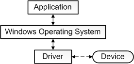
driver

But first the existing driver must be removed from your computer using the FTDI CDMUninstaller tool. This tool should be self-explanatory.

One more consideration. Windows regularly checks to see if any of your drivers are out of date. If your FTDI driver gets updated, possibly automatically,  you will be right back where this all began. With a bricked device.

To avoid this, you can trick Windows into thinking your older driver is in-fact, the most current. Just edit the ftdibus.inf and ftdiport.inf files as follows prior to installing the device driver:

change the line from:

DriverVer=07/12/2013,2.08.30

to:

DriverVer=07/12/2023,2.08.30

Credits

The following posts provided the essential information I needed to unbrick my Arduino-compatible nano…a.k.a China clone. Many thanks! These posts provide some of the details I have left out of this post. This info may prove to be useful in resolving your Arduino nano FTDI issues…

 Conclusion

Having a bricked device is always an unsettling feeling. Yet like most challenges in this DIY game, there is usually a remedy. Sometimes it takes some persistent effort to make things right. But what a relief when things are made whole again. Rest easy. Armed with the solutions presented here , you now know how to make those cheap Chinese clones behave as intended.

I hope this information helps solve your FTDI issues…
Loading

Share This:
FacebooktwitterredditpinterestlinkedintumblrFacebooktwitterredditpinterestlinkedintumblr

Linux Programming Without Installing Anything

puppy-linux

Have you ever thought about learning Linux?  Only to stop short after a bit of exploring. Too intimidating? Difficult to get started.

I’ve felt that way many times. But then I had a need that required Linux. Had to have it working to solve a pressing problem, And I did not want to dedicate a computer just for the cause.

Hard drive partitioning came to mind. Dual booting to either Windows or Linux. Messy for sure. Definitely not portable from one computer to another.  There had to be a better way.

The answer was simple…

Setup a Linux distribution on a USB stick. Boot to Linux with the stick installed, boot to Windows with the stick removed .

<strong>Windows remains intact. With this approach, nothing is installed on the computer.
</strong>

Hmmm. But how do you set it up? And after that, how to you write, compile and execute programs? Sounds complicated.

It’s not. Here is a quick and easy way to set things up….

What you need for this guide:

  • x386 based PC capable of running Windows OS
  • USB stick with 4GB capacity or more

We start with the blank USB stick. Then head over to this site to download a copy of “Puppy Linux”. For this setup, we are going to use Puppy Linux, a light-weight distribution that is easy-to-use, perfect for a first-time user.

To download the software, first click on the “Select Distribution” pull-down and scroll down to “Puppy”. I recommend selection of the “Tahrup” option from the list. The “release announcement” link will provide access to the download. You will need 2 files;

  1. The ISO image
  2. The “devx” SFS file. This contains the compiler and other software tools

You can get both of these files at this site.

Great, now you just need to get the USB installer program and your ready to put it all together. Pick up your copy here.

The installation is simple. Just install your USB stick and start the installer program. The start up screen will provide 3 easy-to-follow instruction steps.

  1. Select the distribution (Select “Puppy”)
  2. Select the iso file (from the folder that has the downloaded ISO image)
  3. Select the USB stick drive letter.

Once this is complete, simply copy the downloaded “devx” SFS file to the root folder of the USB stick. You are now just one step away from completing the setup. All that remains is configuring Linux to startup with the software development tools active.

How?

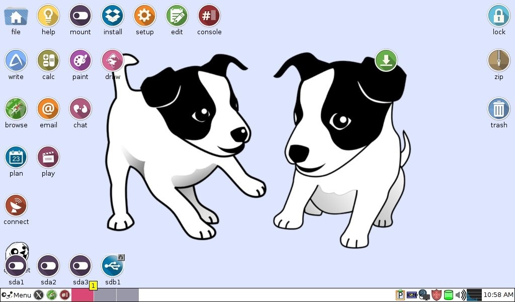
All you need to do is reboot your computer with the USB stick attached and the PC set to boot first from the USB drive. The start screen should look similar to this…

puppy-start

Congratulations on making it this far.

You have successfully booted up to the Linux OS. But have no fear, nothing has been written to your hard-drive. You can return to your normal PC configuration at anytime by rebooting with the USB stick removed.

Now, on to the task at hand…

Starting up Linux with the development tool set.

Good news is that you only need to do this once. First, click on the menu in the lower left hand of the start-up screen, selecting:

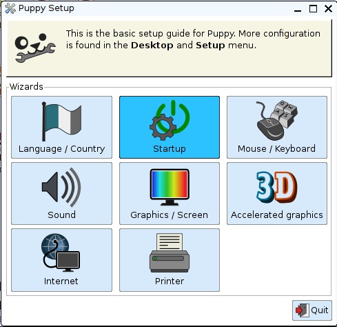
Menu>Setup>Puppy Setup.

Then click on the “Startup Icon

select-startup

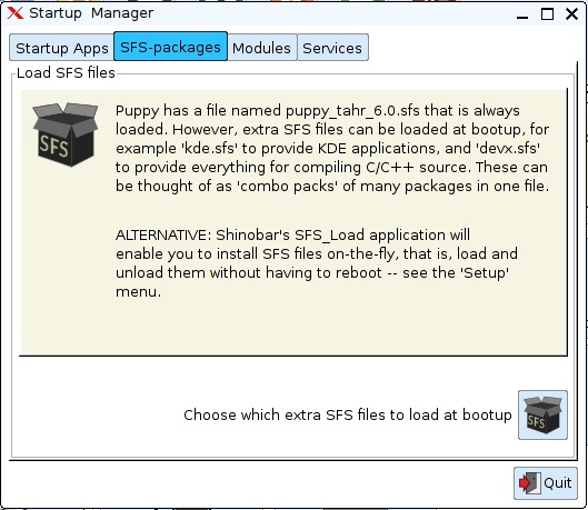
Next, select the “SFS-packages” tab and click on the icon labeled:

“Choose which extra SFS files to load at bootup”

select-sfs

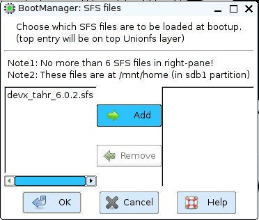
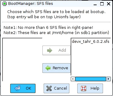
The file “devx_tahr_6.0.2.sfs”, the file you put in the USB root folder, should be listed on the left. Select it and click on the “Add” button.

add-sfs

Click “OK” to complete the SFS package at startup selection.

ok-sfs

Now close all the open windows and reboot Linux from the menu.

Menu>Exit>Reboot

That’s it!

Everything is in place to create and execute programs now. To test this setup, let’s code and run the classic “Hello World!” program…

Let’s keep things tidy by creating a folder for programs we create. And to keep things visible when we use the USB stick with the Windows OS running, the folder needs to be located under the “Home” folder. That is the Linux folder that appears as the “root” folder under the drive letter assigned by Windows.

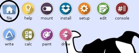
To navigate to the Home folder using the Puppy GUI, first click on the “file” icon from the startup screen.

select-file

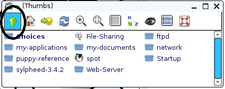
Click on the left “up arrow” icon to get to the parent folder.

parent-folder

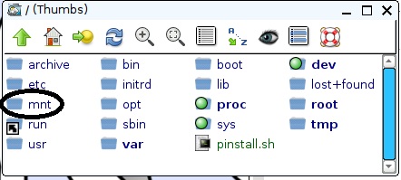
Then select the “mnt” folder.

folder-mnt-sel

And finally, the “Home” folder.

home

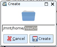
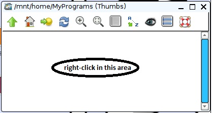
To create a folder, right-click the mouse in the home folder list of files and select:

New>Directory

folder-create

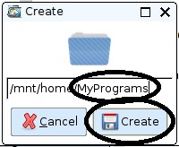
Change “NewDir” to “MyPrograms” and click on the “Create” button.

folder-create-MyPrograms

Now click on the “MyPrograms” folder. We shall now create one additional folder under this one for our first program. Just like before, to create a folder, right-click the mouse in the MyPrograms folder list of files and select:

New>Directory

Change “NewDir” to “HelloWorld” and click on the “Create” button.

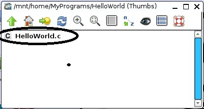
Now click on the “HelloWorld” folder. This time, to create our source code file, right-click the mouse in the HelloWorld folder list of files and select:

New>Blank file

folder-MyPrograms-Blank

Change “NewFile” to “HelloWorld.c” and click on the “Create” button.

Click on the file listed as “HelloWorld.c” to open the file editor.

select-helloworld-file

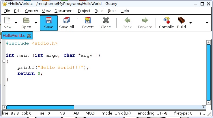
For the minimal first program, enter the following:

save-helloworld

Click on the “save” icon to finish the creation of this file.

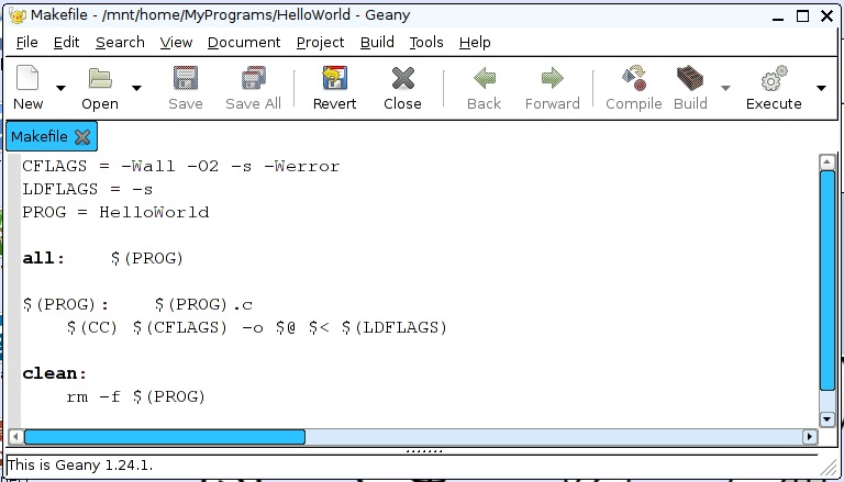
Now we need a “Makefile” to define how to compile and build the program. This will be a minimal Makefile for this first program. Just like the “c” file, create a file named “Makefile” and enter the following contents:

makefile

Got it? Now we are ready to build and execute the program. This can be done two different ways.

  1. Using the GUI editor we currently have open.
  2. From the command line.

Since the GUI file editor is already open, let’s first build and run the program from that environment. This is really easy. Like 1-2-3…

Build and Execute Using the GUI

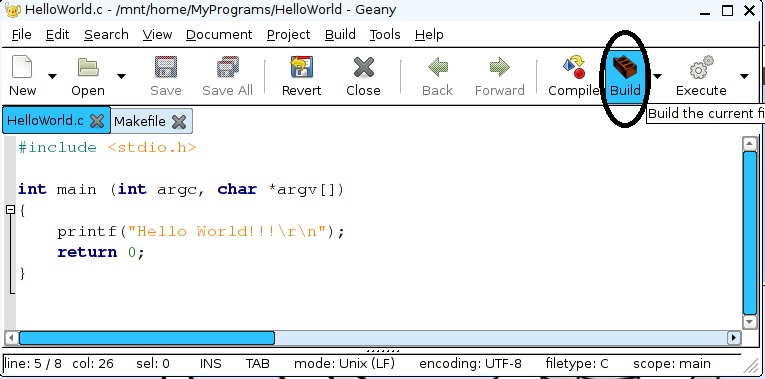
Step 1: Select the “HelloWord.c” source code file tab.
Step 2: Click on the “Build” icon.

build-helloworld
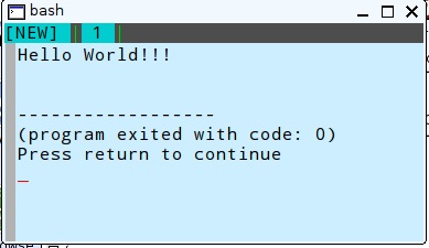
Step 3: Click on the “Execute” icon.

execute-helloworld

Our one-line “prinf” command correctly displays on the console when the program is executed.

That’s great for a quick compile and run. But what I found is that if your program contains errors, nothing is displayed indicating what went wrong. Fortunately, there is a way to get needed error messages, when they occur.  It requires you to use the command line to build and execute.

Fear not! It really is not that difficult…

Build and Execute Using the Command Line

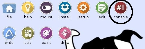
Now let’s do the same thing from the command line. To open a command line window, click on the “console” icon.

start-cmd-line

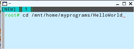
Then switch to the HelloWorld Folder:

change-dir-hello

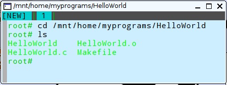
You can view a directory listing now to verify the source and “Makefile” files are present with the “ls” command.

dir-listing

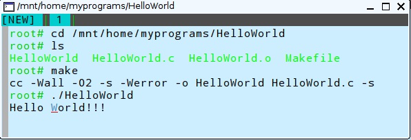
Now we can build the program with the “make command”. And run the program with the “./HelloWorld” command.

cmd-line-demo

That’s it. You are now setup to build and execute programs built for Linux.

Now let’s see what happens if we put an error into the program. Enter a bogus line after the printf statement. Like “junk;”, for example. When we try to “make” this program with the error injected, an error is returned. Unlike the GUI, with no error information provided, this provides you with an indication of what went wrong.

So you can quickly correct the error.

error

Conclusions

Here you have a simple reference to use to setup a Linux development environment. It is another tool to add to your “bag of tricks”. You never know when it will be needed. Like when the only solution available must be run using Linux.

It’s up to you now to explore Linux further. This open-source OS is well supported. You will find all the information you need, as you need it, on-line using basic keyword searches. So have some fun with it!

Hope you find this information useful.

Loading

Share This:
FacebooktwitterredditpinterestlinkedintumblrFacebooktwitterredditpinterestlinkedintumblr

Expanding Arduino Serial Port Buffer Size

thingspeak

I recently came across a challenge while working with an Arduino serial interface. I suspect many others have also encountered the same issue. And the solution could save you precious time. So here it is…

After playing with an Arduino for a while, collecting sensor data, the logical next step is to add a method of saving this data for future consumption.

But where?

One option is to add an SD card or some similar storage device to your Arduino circuit. That would protect the data from system crashes. But there is a shortcoming with this approach…

You cannot get access to the data unless the Arduino is running, and you are located in the same area as the system. This approach, if relied solely for data storage, keeps your system isolated, Not exactly an IoT solution.

Saving the data somewhere independent of the hardware that first acquired the information makes more sense. In the cloud if possible.

Many turn to ThingSpeak. This free service supports up to 8 updates at a time. The API uses a single http “GET” request for this purpose. The strings are typically 100-150 characters long, data dependent of course.

No problem, right? Since the Arduino often uses a serial to WIFI device (like an ESP8266), all you need to do is write the string to a serial port. A very simple one-line sketch command.

Yet there lies the essence of the problem….

Really? What is so hard about writing a string to a serial port? Well, here is the rub…

You see, the Arduino Serial port buffers only hold up to 64 bytes by default. Try to send a string longer than 64 bytes and it will be truncated. Cut off at the buffer size. Not exactly what you want.

I’ve run into this and found that there are two different solutions. The one to use depends on whether you are using a hardware or software serial port.

It is important to note that these changes are at the Arduino core level. This means that every serial port used in all your projects are effected by this change. These minor file changes need to be undone for projects that work just fine with the default 64 byte buffer size.

The reason you may not want to expand the buffer all the time is that the buffer consumes valuable Arduino RAM. An ATmega328 based Arduino, typical in many models, only has 2048 bytes of run-time RAM available. With two separate serial port buffers (on for Tx, one for Rx), changing the buffers from 64 to 256 bytes  increases the RAM requirements from 128 bytes to 512 bytes. That is a full 25% of the available RAM for your entire sketch.

The Arduino Mega is the model of choice if extra RAM is important. This beast sports the ATmega2560 chip which provides 8192 bytes of RAM and 4 hardware serial ports.

Software Serial Buffer Expansion

The change for software serial ports require a simple modification of the file:

<base Arduino folder>\hardware\arduino\avr\libraries\SoftwareSerial\SoftwareSerial.h

Change:

__#define _SS_MAX_RX_BUFF 64 // RX buffer size

To:

__#define _SS_MAX_RX_BUFF 256 // RX buffer size

Hardware Serial Buffer Expansion

The change for hardware serial ports require a simple modification of the file:

<base Arduino folder>\hardware\arduino\avr\cores\arduino\HardwareSerial.h

Change:

__#define SERIAL_TX_BUFFER_SIZE 64
__#define SERIAL_RX_BUFFER_SIZE 64

To:

__#define SERIAL_TX_BUFFER_SIZE 256
__#define SERIAL_RX_BUFFER_SIZE 256


I hope this information proves to be useful….

Loading

Share This:
FacebooktwitterredditpinterestlinkedintumblrFacebooktwitterredditpinterestlinkedintumblr

IR Remote Using ESP8266


Even though I live alone, there are 4 TVs spread around my house. And since only 1 set is needed at a time, only one DVR box is needed. So I used a 1-4 HDMI splitter/driver to distribute the signal from the one box to the 4 TVs. Using the attic pathway, direct connections were made to each of the sets. It was pleasing to see that the active HDMI splitter could drive the remote TVs without any pixelation or frame freezes. The furthest HDMI cable required 100 feet. But here was the problem…

The remote would only work when pointed directly at the DVR. Sure, my Att-Uverse service includes a free smartphone App to use as a remote control for the other TVs. But that experience is not the same as using the physical remote that you get with the DVR.

I did have one IR transmitter/receiver pair that I purchased off-the-shelf. Works great! But at nearly $50, it just seemed a bit cost prohibitive to add additional pairs for the other 2 sets. So that got me thinking…

Hmmm. A micro-controller would work. But the relatively high cost of an Arduino, Raspberry Pi or Particle WIFI enabled system was unappealing. So this looked like another opportunity to deploy the low cost ESP8266 as a solution. Here is what I came up with…

IR Remote Solution using ESP8266

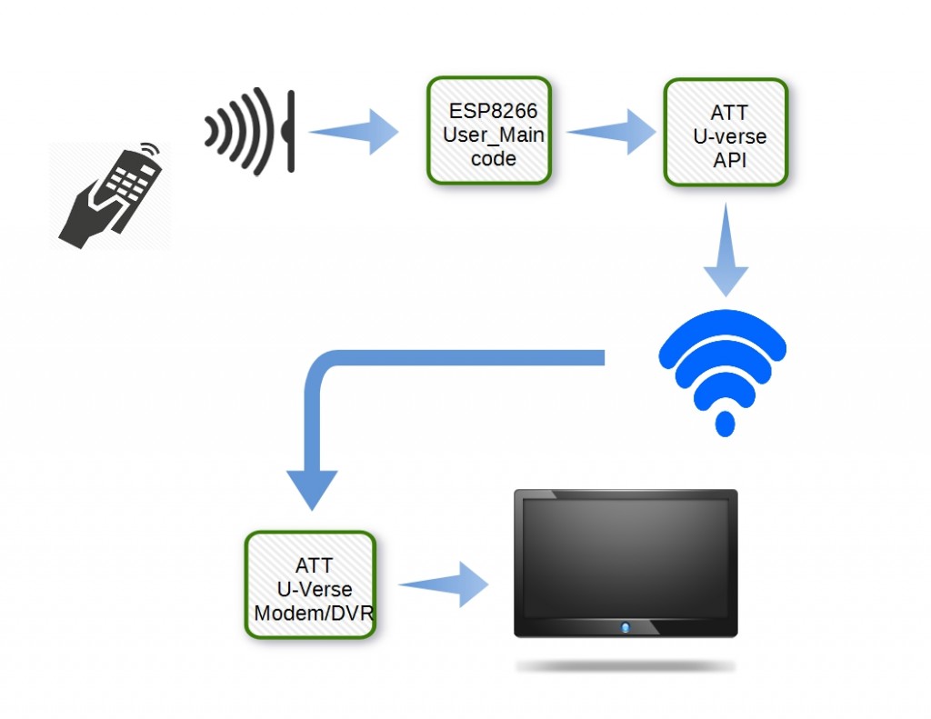
Initially, I wanted a system that used an ESP8266 positioned locally at the TV set, one setup for each television. The system would use an IR sensor to read the remote code to determine which button was pressed. Then, the ESP8266 code would take advantage of the AT&T U-verse® Enabled SDK. This interface would, based on the button pressed, send commands to the DVR, over an internet connection.

att

But there was a problem…

You see, the SDK only supports mobile apps using iOS or Android platforms. While I believe there is a way to port the java-based SDK to the ESP8266 embedded platform, it is not an endeavor I wish to pursue at this time. That’s the problem-it will take too much time. I was hoping that ATT would provide the solution.

So I sent a request to ATT to provide an SDK suitable for micro-controller use. We shall see what they have to say about that. You never know unless you ask…

Plan B: Adding another ESP8266 at the DVR

In order to move forward with this project, an alternate approach was needed. One that could be totally controlled within the framework of a micro-controller system. Without the need for a 3rd-party API.

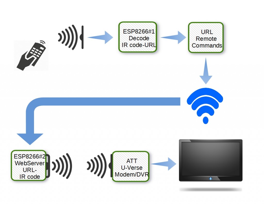
I really just came up with a tweak of the original concept. Instead of using the ATT SDK, the IR commands would be sent to the second ESP8266 setup, using an web-server client command. This added unit, functioning as a web server, would be responsible for receiving the remote control commands and then transmitting the corresponding IR code to the DVR, using an IR Diode similar to the type found in remote controllers.

esptxrx

ESP8266 IR Remote Hardware Configuration

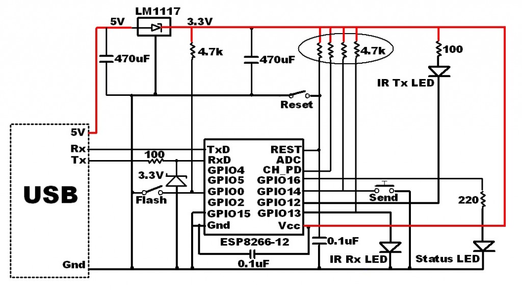
Here is the schematic of the circuit I used to check out the ESP8266 IR Send/Receive software.

ESP8266-IR

The left side of the ESP8266 is the standard design I use for all projects. It has proven to be very stable, with hundreds of flash cycles completed successfully and no unintended resets during operation.

Three LEDs are used in the circuit:

  1. Status LED – A standard LED used to provide visual feedback.
  2. IR Tx LED – Sends IR data to the DVR
  3. IR Rx LED – Receives IR data from the DVR remote control.

In addition, a simple push-button switch is used to send the last code saved to the DVR.

This circuit contains all the hardware needed for both ESP8266#1 and ESP8266#2. As you can see, there are only a few components needed. It is probably wise to stick with this single hardware configuration for both ESP8266 setups.

However, once tested and all the remote codes have been “learned” and saved, the two ESP8266 systems could be optimized as follows.

ESP8266#1:

IR Transmit LED, Send switch and Status LED could be removed. The only thing needed is the receive IR. Remember, a separate ESP8266#1 circuit can be used for each TV you wish to control with a single DVR box.

ESP8266#2:

IR Receive LED, Send switch and Status LED could be removed. The only thing needed is the Tx IR. Only one of these circuits will be needed, regardless of how many remote TVs are used.

IR Remote Control Signals

There are many great articles that provide details on how IR signals are generated, transmitted, received and decoded. Instead of repeating, here are a few references for further reading, if you want to know more. This post will concentrate on an ESP8266 IR remote solution.

ESP8266 IR Test Software

My initial idea was to port an existing IRremote library from the proven Arduino platform to the ESP8266. The obvious choice was the “RobotRemote” library provided as a standard Arduino IDE library. But the differences in the ESP8266 hardware from the Arduino ATmega chip made the porting difficult.

Even after resolving all the compile errors, I could not complete a successful link to all the libraries. Eventually I ended up abandoning the Arduino IDE platform for this project in favor of the EspressIF SDK.

But this decision came with additional challenges as the SDK does not easily support c++ class libraries. Like the “RobotRemote” library. This issue was overcome by decomposing the class structure into separate ANSI C functions.

But there was more to deal with…

Remote IR Signal Generation

The Arduino library relies on the PWM capability to generate the standard 38 kHz IR modulation frequency. Unfortunately, the ESP8266 PWM API only supports up to 100 Hz, a far cry from the needed bandwidth.

Fortunately, there is a way around this ESP8266 constraint. The trick is to create the 38 kHz modulation by simply toggling a digital output; logic 1 and logic 0. The duration of these pulses determine the command sent to the remote receiver. But how do we generate 38 kHz pulses?

Simple…

Using the ESP8266 micro-second delay statement “os_delay_us(us)”, we can create a 38 kHz pulse train. Each pulse period is 1/38000 seconds (26.3 us) long. Rounding that off to 26 us, the modulation frequency is easily achieved with:

  loops = time/26;                    // "time" units are microseconds
  if(loops==0) loops=1;
  for (i=0;i&lt;loops;i++) { 
          gpio_write(IR_SEND_PIN, 0); //Set GPIO12 LO -&gt; IR On
	  os_delay_us(13);  //1M/38K/2
	  gpio_write(IR_SEND_PIN, 1); //Set GPIO12 HI -&gt; IR Off
	  os_delay_us(13);  //1M/38K/2
  }

Here, each iteration of the loops generates one 38kHz pulse (26 us). The number of pulses (loops) is determined by the desired number of microseconds.

Remote IR Signal Detection

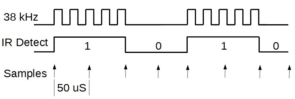
In addition to generating IR codes, we must also be able to detect and decode IR signals received from a remote. That requires a sampling of the state of the IR detector diode (is it HI or LO). A 50 us timer callback function is implemented for this purpose, which is the same 20 kHz sampling frequency used by the original Arduino RobotRemote library. Since the 38 kHz modulation is removed by the IR detector, the remaining signal content (set of ones and zeroes) change at a lower rate. As result, the 50 us sample rate is adequate to accurately decode the incoming IR code.

demodulation

Initial Implementation

My initial implementation provides a framework upon which to build an ESP8266 based IR remote application. It is not meant to be a complete application, merely a platform to prove the concept. From this structure, it will be possible to easily adapt the code for your specific needs. I plan to follow-up this post with my final design.

From the current structure, it will be a straightforward task to record and store all the IR remote codes for subsequent replay, on demand, by the ESP8266#2 web server.

Here is what this project currently does:

  1. With the push-button in the schematic open, the IR detector is monitored every 50 us for the presence of an IR code. Every time a logic state is detected  on this  sensor, the LED connected to GPIO16 is blinked. In addition, the received code is sent to the serial port. Once a valid code is detected, it is stored for playback, on-demand,  by the IR emitter diode.
  2. When the push-button in the schematic is pressed, the IR detection process is stopped and the last IR code store is transmitted. The code is repeated every 0.5 seconds as long as the button is pressed. IR detector sampling will resume once the button is no longer closed.

The code for this project is on Github here.

What to do next

Note that the IR codes sent to the serial output can be saved using any terminal program that saves the output to a file. By sequentially walking through each key on a remote, a map of button pressed to IR code can be created. This map will have 2 purposes in the final design:

  1. ESP8266#1:  The received code can be “looked up” in the map, to determine which remote key was pressed.
  2. ESP8266#2: Once the Web server receives a command to send a key code, the map will identify the code to send for that key.

The one shortcoming I have observed with this initial design is the limited range for both sending and receiving IR signals. Currently, the signal fades and starts to drop out beyond only 1 meter. This has one of two possible causes, which I intend to investigate.

Either the signal intensity is inadequate or the signal MARK/SPACE timing is off. We shall see.

I blew up a couple of IR Emitter Diodes using a transistor to increase the LED intensity. As results, a more thorough evaluation is needed before I proceed with additional modifications. I will provide additional information when a better solution is reached.

Conclusions

The project presented here provides a solid foundation for any ESP8266 application using IR communication. This design uses the EspressIf SDK but could most likely be adapted to work with the Arduino IDE. So that others may benefit, please post your work in the comments below if anyone has ported this to the ESP8266 Arduino IDE platform.

Hope you find this information useful…

Loading

Share This:
FacebooktwitterredditpinterestlinkedintumblrFacebooktwitterredditpinterestlinkedintumblr