Archives for October 2015

ESP8266 Dual AT & Web Server Mode

Here is an exciting framework for fully utilizing the huge capabilities of the ESP8266.

This is an original.

Something that I have not seen anywhere before. You see, using this structure opens up many more possibilities and applications for this amazing device…

Most folks in the ESP8266 world seem to fall into one of two camps. The first group, typically diehard Arduino developers, want to use the ESP8266 as a serial to WIFI shield. A couple bucks to add WIFI to the very popular Arduino platform is most cost effective method of bringing it on-line. Much cheaper than alternative WiFi shields.

Others see the ESP8266 as a complete solution. It is often referred to as a System On a Chip (SoC). They not only use the ESP8266 for WIFI internet access, but also use the platform to read sensors, control “things”, process data and provide web server functionality.

Among The Examples

The majority of those that have delved into the ESP8266 world started by loading the serial to WIFI firmware often referred to as the AT command set. This is available as a binary file downloaded to the ESP8266 via it’s serial interface. That’s where I began my ESP8266 journey.

It was not long after my start that I searched for the AT firmware source code. Fortunately, it is available within earlier versions of the EspressIf SDK. You see, prior to version 1.0, many example applications were included in the development package. And yes, the AT command set was among these examples.

The other most useful example application is the IoT_Demo. This software has survived every release of the SDK, including the current version. This example provides a framework for a web server to make your “things” Internet accessible.

After studying the software structure of these examples I got to thinking…

Wouldn’t it be great to merge these two applications? So you benefit from both features?

It indeed did look feasible.

The combined application would not only service AT commands through the serial port, but also service http GET or POST commands via the Internet.

And that’s not all…

This single ESP8266 firmware application could also be used to read sensors and control devices.

I am stoked to say I have successfully merged these examples. This broadens the capabilities and applications of a single ESP8266 based system.

It works!

Here’s how…

ESP8266 Dual Server Architecture

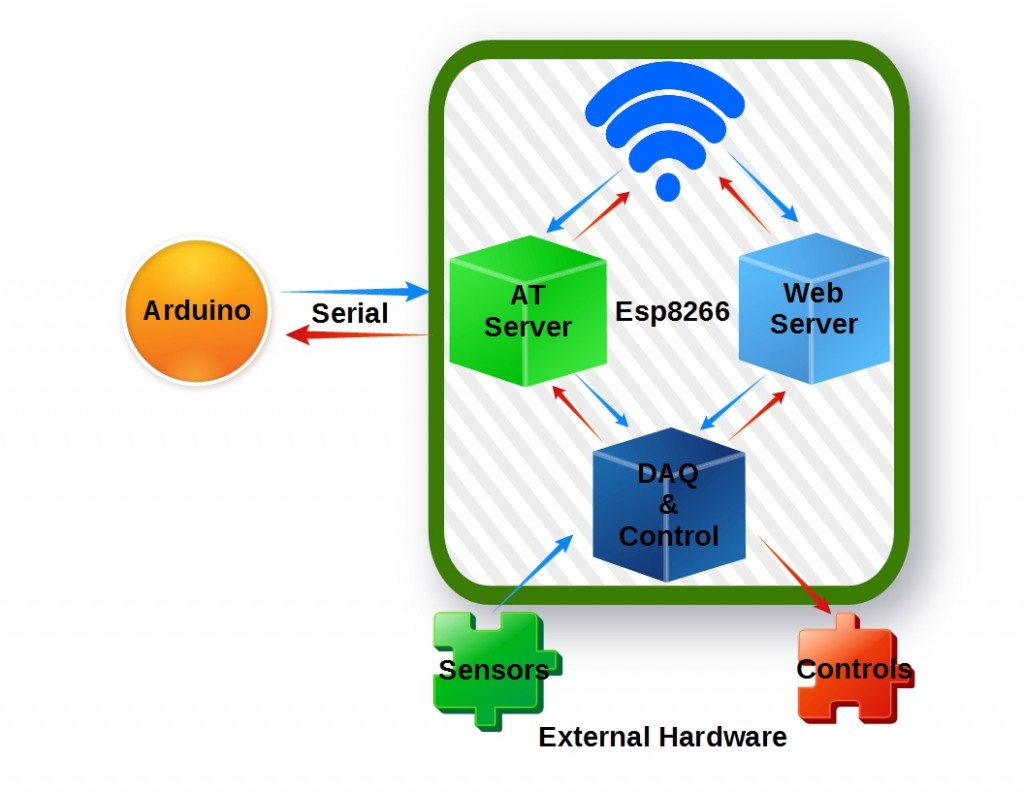
The ESP8266 is used to perform 3 primary functions. First, it provides basic serial to Wifi capability using the standard AT command set that many first-time users tinker with. Note that since the design presented here includes the AT firmware source code, the command set can be expanded to also provide access to the Esp8266 Daq and Control features. This is depicted in the following diagram as two-way arrows from the AT Server.

dualserver

The ESP8266 also provides Web Server functionality. This feature operates completely independently from the serial AT Server. The web server responds to http GET commands received form the Internet via the built-in Wifi capability. Just like the AT Server, the Web Server has access to the Daq and Control functions.

And finally, the data acquisition (DAQ) and control function, also running independently from the other two features, controls all the Esp8266 outputs and receives all the sensor inputs. Because of the many possible sensors connected to the system, the DAQ function must be managed so that it does not monopolize the Esp8266 processor. This is accomplished by limiting it’s execution to the reading of one sensor each time the function is called.

Task Distribution

Separate callbacks are registered for each of the three ESP8266 primary functions. Both the AT and Web Server callbacks are event driven. They are only executed upon user request. The AT callback is executed anytime data is received on the serial port, while the Web Server callback is run upon receipt of an http GET request.

The callback for the Daq/Control features are different. This feature is set up to execute periodically (once every second) from a Timer callback. This keeps the sensor data fresh, available for consumption by the AT or Web Server, upon request.

AT Callback – The AT serial port server callback is installed in the uset_init() function when at_init() is executed. The AT server responds to any of the requests defined in at_cmd.h.


  1. at_funcationType at_fun[at_cmdNum]={
  2. {NULL, 0, NULL, NULL, NULL, at_exeCmdNull},
  3. .
  4. .
  5. {"+CIPSERVER", 10, NULL, NULL,at_setupCmdCipserver, NULL},
  6.   {"+CIPMODE", 8, NULL, at_queryCmdCipmode, at_setupCmdCipmode, NULL},
  7.   {"+CIPSTO", 7, NULL, at_queryCmdCipsto, at_setupCmdCipsto, NULL},
  8.   {"+CIUPDATE", 9, NULL, NULL, NULL, at_exeCmdCiupdate},
  9.   {"+CIPING", 7, NULL, NULL, NULL, at_exeCmdCiping},
  10.   {"+CIPAPPUP", 9, NULL, NULL, NULL, at_exeCmdCipappup},
  11.   {"+GETSENSOR", 10, NULL, NULL, at_exeGetSensorVal, NULL},

The new request, “+GETSENSOR”, has been added to provide a method for the serial port server to get the sensor readings. Upon receiving this request, the function at_exeGetSensorVal() is called. This function returns the current sensor reading over the ESP8266 serial port.


  1. void ICACHE_FLASH_ATTR
  2. at_exeGetSensorVal(uint8_t id, char *pPara)
  3. {
  4.       int isensno = atoi(++pPara);
  5.       switch(isensno) {
  6.             case 1:
  7.                   uart0_sendStr(tInside);
  8.                   break;
  9.             case 2:
  10.                   uart0_sendStr(tOutside);
  11.                   break;
  12.             case 3:
  13.                   uart0_sendStr(tAttic);
  14.                   break;
  15.             case 4:
  16.                   uart0_sendStr(tDht11);
  17.                   break;
  18.             case 5:
  19.                   uart0_sendStr(hDht11);
  20.                   break;
  21.             case 6:
  22.                   uart0_sendStr(pBmp085);
  23.                   break;
  24.             case 7:
  25.                   uart0_sendStr(tBmp085);
  26.                   break;
  27.             case 8:
  28.                   uart0_sendStr(aBmp085);
  29.                   break;
  30.             default:
  31.                   uart0_sendStr("out of range");
  32.                   break;
  33.       }
  34.       uart0_sendStr("\r\n");
  35. }

The requests are made by sending the following string over the serial port:

AT+GETSENSOR=n

“n” is the sensor number and corresponds to the case number in the code above.

As you can see, it is not difficult to add your own custom commands to the standard ESP8266 AT command set.

Web Server Callback – This application uses the Web Server code provided in the IoT_Demo example. The user_init() function sets up and connects to the local Wifi before launching the Web Server. The callback webserver_recv() is registered during the initialization sequence. That function is executed any time an http GET request is received.

For this demo application, the Web Server only responds to “request-GetSensors”. More requests can be added as noted in the code that follows. When received, the server replies by sending a JSON string containing all the sensor readings.


  1. LOCAL void ICACHE_FLASH_ATTR
  2. webserver_recv(void *arg, char *pusrdata, unsigned short length)
  3. {
  4.     URL_Param *pURL_Param = NULL;
  5.     char *pParseBuffer = NULL;
  6.     bool parse_flag = false;
  7.     struct espconn *ptrespconn = arg;
  8.     int i;
  9.     espconn_set_opt(ptrespconn, ESPCONN_REUSEADDR);
  10.     if(upgrade_lock == 0){
  11.           parse_flag = save_data(pusrdata, length);
  12.         if (parse_flag == false) {
  13.               response_send(ptrespconn, false);
  14.         }
  15.         pURL_Param = (URL_Param *)os_zalloc(sizeof(URL_Param));
  16.         parse_url_params(precvbuffer, pURL_Param);
  17.         switch (pURL_Param->Type) {
  18.             case GET:
  19.                 if(os_strcmp(pURL_Param->pParam[0], "request")==0) {
  20.                     <strong>// GetSensors is the only request the server currently supports</strong>
  21. <strong>                    if(os_strcmp(pURL_Param-&gt;pParVal[0], "GetSensors")==0) {</strong>
  22. <strong>                          json_send(ptrespconn, GET_SENSORS);</strong>
  23. <strong>                    }</strong>
  24.                     // Add additional requests here
  25.                 }
  26.                 json_send(ptrespconn, CONNECT_STATUS);
  27.                 break;
  28.             case POST:
  29.                   ets_uart_printf("We have a POST request.\n");
  30.                  break;
  31.         }
  32.         if (precvbuffer != NULL){
  33.               os_free(precvbuffer);
  34.               precvbuffer = NULL;
  35.         }
  36.         os_free(pURL_Param);
  37.         pURL_Param = NULL;
  38.     }
  39.     else if(upgrade_lock == 1){
  40.           local_upgrade_download(ptrespconn,pusrdata, length);
  41.             if (precvbuffer != NULL){
  42.                   os_free(precvbuffer);
  43.                   precvbuffer = NULL;
  44.             }
  45.             os_free(pURL_Param);
  46.             pURL_Param = NULL;
  47.     }
  48. }


Acquisition/Control Timer Callback – This callback serves as the application’s periodic loop() function. It is called once every second. The functions is mechanized as a state machine. In this example, 5 states are implemented, one for each sensor in the system. Exactly one state is executed each time the function is called. Upon completion of the sensor read, the code is set to execute the next state the next time the function is called. The code can be modified as needed to add or delete states and sensor hardware.


  1. LOCAL void ICACHE_FLASH_ATTR loop_cb(void *arg)
  2. {
  3.     char szT[32];
  4.     DHT_Sensor DHsensor;
  5.     DHT_Sensor_Data data;
  6.     DHsensor.pin = 5;  //GPIO14
  7.     DHsensor.type = DHT11;
  8.     int32_t temperature;
  9.     int32_t pressure;
  10.     //---------------------------------------------------
  11.     //This state machine reads 1 sensor each iteration
  12.     //---------------------------------------------------
  13.       switch(nTcnt%5) {
  14.             case 0: //Read first DS18B20 Temperature Sensor
  15.                 get_temp_ds18b20(1,1,tInside);
  16.                 break;
  17.             case 1: //Read second DS18B20 Temperature Sensor
  18.                 get_temp_ds18b20(2,1,tOutside);
  19.                 break;
  20.             case 2: //Read third DS18B20 Temperature Sensor
  21.                 get_temp_ds18b20(3,1,tAttic);
  22.                 break;
  23.             case 3: //Read DHT11 temperature and humidity Sensor
  24.                 DHTRead(&amp;DHsensor, &amp;data);
  25.                 DHTFloat2String(tDht11, ((9/5) * data.temperature)+32);
  26.                 DHTFloat2String(hDht11, data.humidity);
  27.                 break;
  28.             case 4: //Read BMP085 Temperature and pressure Sensor
  29.                 temperature = BMP180_GetTemperature();
  30.                 pressure = BMP180_GetPressure(OSS_0);
  31.                 os_sprintf(pBmp085,"%ld.%01d", pressure/3386,(pressure%3386)/1000);
  32.                 os_sprintf(tBmp085,"%ld.%01d", ((temperature*18)/100) + 32,(temperature*18)%100);
  33.                 os_sprintf(aBmp085,"%03d", 328 * (BMP180_CalcAltitude(pressure)/100000));
  34.                 break;
  35.             default:
  36.                 break;
  37.       }
  38. }

Want the code for this framework? Please feel free to use and modify it for your own custom requirements. It is available on Github here.

Testing the Code

Let’s test the dual server by sending a command over the serial port and via http GET. The command will retrieve sensors values read by the ESP8266. For this test case, the 1 second loop() function has been modified as follows to populate the sensor variables without actually reading any sensors.


  1. LOCAL void ICACHE_FLASH_ATTR loop_cb(void *arg)
  2. {
  3.     //-----------------------------------------------------
  4.     //This test code populates the variables associated
  5. //with the sensor values in lieu of actually reading
  6. //sensors. This code is used to test the functionality
  7. //of the dual server application. All variables are
  8. //set with fixed values except iTinside, which is
  9. // incremented by 1.5 degrees each time this function
  10. //is called.
  11.     //-----------------------------------------------------
  12. if(tI&lt;800) {
  13. tI += 15;
  14. }
  15. else {
  16. tI = 600;
  17. }
  18. os_sprintf(tInside,"%d.%d",tI/10,tI%10); //Sensor 1
  19. os_sprintf(tOutside,"%s","79.2"); //Sensor 2
  20. os_sprintf(tAttic,"%s","88.5"); //Sensor 3
  21. os_sprintf(tDht11,"%s","69.1"); //Sensor 4
  22. os_sprintf(hDht11,"%s","34.7"); //Sensor 5
  23. os_sprintf(pBmp085,"%s","29.7"); //Sensor 6
  24. os_sprintf(tBmp085,"%s","71.1"); //Sensor 7
  25. os_sprintf(aBmp085,"%s","555.0"); //Sensor 8
  26. }

AT Serial Server Test

The added function in this demo application to the AT command set is “AT+GETSENSOR=n”. “n” is filled in with an integer value representing the sensor number. Enter the following to test this new command:

Sensor Serial Port Command Expected Reply
Inside Temperature AT+GETSENSOR=1 increasing value in range 60-80 F
Outside Temperature AT+GETSENSOR=2 79.2
Attic Temperature AT+GETSENSOR=3 88.5
DHT11 Temperature AT+GETSENSOR=4 69.1
DHT11 Humidity AT+GETSENSOR=5 34.7
BMP085 Pressure AT+GETSENSOR=6 29.7
BMP085 Temperature AT+GETSENSOR=7 71.1
BMP085 Altitude AT+GETSENSOR=8 550.0

Web Server Test

The web server can easily be tested by entering a single URL in any web browser. In this demo application, the IP is hard-coded to “192.168.0.106” and the server responds to port 9703 requests. Thus, the test URL is:

http://192.168.0.106:9703/?request=GetSensors

And the expected reply will be the following JSON string:


  1. {
  2. "B_Pressure":"29.7",
  3. "B_Temperature":"71.1",
  4. "B_Altitude":"555.0",
  5. "DS_TempInside":"79.5", &lt;--NOTE: This value will range from 60-80 F in 1.5 degree increments
  6. "DS_TempOutside":"79.2",
  7. "DS_TempAttic":"88.5",
  8. "DH_Humidity":"34.7",
  9. "DH_Temperature":"69.1"
  10. }

Your demo application is working properly if the expected responses are observed.

In Closing

This opens up new possibilities. With this structure, you use the ESP8266 as an Arduino serial to WIFI shield. Yet at the same time use this same ESP8266 as a web server. And a sensor acquisition engine. And to control “things”. All you need to do is add meat to the bones provided here. What will you come up with?

I hope you find this information useful…

Loading

Share This:
FacebooktwitterredditpinterestlinkedintumblrFacebooktwitterredditpinterestlinkedintumblr

ESP8266 Free Space Assessment

percentage

Have you ever used the EspressIf SDK to compile code and wondered how much free space you have? How much more code you can add before running out of memory?

That information is very useful when developing code, and is readily available when using the Arduino IDE. So why is it missing from the SDK console output when you execute a build?

That used to bug me, until I figured out how to include it. Read on if you want a better view of the free space available after building your ESP8266 code.

Here is how I did it…

Evaluating Solution Options

First thing I did was review the Makefile that was provided with the SDK examples. I thought it might be a simple matter of adding a few lines to output the desired information. After all, the current Makefile outputs the number of byte used. And we know how much memory is available. A simple calculation and boom, you got the answer.

Wrong!

What I found was that the current memory statistics are generated by the utility “MemAnalyzer.exe” . This tool is included with the EspressIf SDK. So I figured all that it would take was a few changes to this utility to format the memory statistics in the format I wanted. Problem is, the source code for this utility is nowhere to be found. At least I had no luck finding it.

So what I decided to do was create another utility. One that would format the information provided by MemAnalyzer.exe and include it in the build Console output.

The Solution

Obviously, this requires some changes to the project’s “Make” file. The current information, while I find it inadequate, is produced by the following Makefile file line:


  1.  $(Q) $(SDK_TOOLS)/memanalyzer.exe $(OBJDUMP).exe $@

And the output from the memanalyzer tool is displayed like this example:


  1.    Section|              Description| Start (hex)| End (hex)|Used space
  2. ------------------------------------------------------------------------------
  3.       data|   Initialized Data (RAM)|    3FFE8000|  3FFE8D8C|    3468
  4.     rodata|      ReadOnly Data (RAM)|    3FFE8D90|  3FFEA3F4|    5732
  5.        bss| Uninitialized Data (RAM)|    3FFEA3F8|  3FFF4C08|   43024
  6.       text|       Cached Code (IRAM)|    40100000|  4010782C|   30764
  7. irom0_text|      Uncached Code (SPI)|    40240000|  4026F574|  193908
  8. Total Used RAM : 52224
  9. Free RAM : 29696
  10. Free IRam : 2022

In order to access this information, it was redirected to a text file (mem.txt) by adding a new line to the MakeFile:


  1. $(Q) $(SDK_TOOLS)/memanalyzer.exe $(OBJDUMP).exe $@
  2. <strong><span style="color: red;">$(Q) $(SDK_TOOLS)/memanalyzer.exe $(OBJDUMP).exe $@ &gt;mem.txt</span></strong>

My new utility reads the mem.txt file and outputs the re-formatted memory statistics to the build Console. The utility is named “EspMemUsage.exe” and is called in the Makefile with the addition of a second line:


  1. $(Q) $(SDK_TOOLS)/memanalyzer.exe $(OBJDUMP).exe $@
  2. $(Q) $(SDK_TOOLS)/memanalyzer.exe $(OBJDUMP).exe $@ &gt;mem.txt
  3. <strong><font style="color: red;">$(Q) $(SDK_TOOLS)/EspMemUsage.exe $(OBJDUMP).exe $@</font></strong>

And here is what the added Console output information looks like:


  1. ------------------------------------------------------------------------------
  2. Resource            |Size(bytes)|    Used|       %Used|        Free|   %Free
  3. --------------------|-----------|--------|------------|------------|----------
  4. IRAM - Cached Code  |      32768|   30746|          94|        2022|       6
  5. SPI - Uncached Code |     253952|  193908|          76|       60044|      24
  6. RAM - Data          |      81920|   52224|          63|       29696|      37
  7. ------------------------------------------------------------------------------

It help me a lot to see the memory usage in this format. I hope you find it useful too.

The utility, makefile, and source code are available on Github here. Installation instructions are provided in the readme file. It was developed using the free Microsoft code development  tool Visual Studio 2015 Community. Customize as you see fit to meet your specific needs and wants.

What It Does

The utility code is written using the c# programming language. The Program class is structured into 3 static functions.

  1. Main – This console application executes Main upon entry.  Main opens the file “mem.txt” and reads each line separately. If the line contains a memory value of interest, the information is extracted and formatted for output by calling the function “MemStat”. After completing the evaluation of the file “mem.txt”, the formatted results are output to the console.
  2. MemStat – This function extracts the value from the line read. Any spaces in the extracted value are removed by calling the 3rd and final function, “RemoveSpaces”. The memory used and free statistics are then calculated and formatted. The formatted string is returned to the function caller.
  3. RemoveSpaces – Removes spaces from a string.

In Closing

The utility presented here provides clarity to the ESP8266 code developer using the EspressIf SDK. So you know exactly how much memory is available for expansion, delineated by memory resource. Once installed, all you need to do is use the modified Makefile in your new projects to get the information displayed in the console output.

I hope you find this information useful.


Loading

Share This:
FacebooktwitterredditpinterestlinkedintumblrFacebooktwitterredditpinterestlinkedintumblr

Capturing ESP8266 Max Value on ThingSpeak

This article provides a method to capture and store the maximum value reached in a ThingSpeak channel field.

So what’s the big deal? You’ve got all the data captured. Just retrieve the data points and search for the maximum among them. Well, read on…

You see, like many users, my ThingSpeak channel receives data captured by an ESP8266 micro-control unit (MCU). Both ESP8266 System Status and Sensor data are collected.

One of my key data points of interest is the lapse time between ESP8266 resets. The value is saved to the ThingSpeak channel in a field containing the ESP8266 ms running time. This, along with the sensor data is added to the channel data once each hour.

What I found was that reading all of the captured data and searching through it for a maximum value became increasingly slower as my database record count grew. It needed to run quicker. So I came up with a simple solution…

A method of comparing each new ESP8266 reading with the maximum value saved in a ThingSpeak channel field. This requires a CRON script running on my web server. The script is executed once every 20 minutes. What? It’s really not that complicated.

Here’s the details…

System Overview

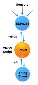
The system is comprised of an ESP8266, a web host server capable of running CRON scripts, and a ThingSpeak channel. The CRON script is the key component used to move the information from the ESP8266 to the ThingSpeak channel.

The ESP8266 runs it’s own firmware serving two primary purposes. Periodically, it refreshes sensor readings and various system parameters, including the MCU run time since the last reset. This process runs on an internally registered timer callback.

The ESP8266 also acts as a web server. In this capacity, the server responds to http GET requests, returning sensor and system values in JSON format.

It should be noted here that this is not limited to an ESP8266. Any MCU capable of these two functions can be used.

overview

PHP CRON Script

So what exactly is a CRON script?

CRON originated in the Unix world. In this case, it is simply a service provide by the web host to automatically execute a script at a predetermined time. There are a couple of  options available to deploy automated scripts for data exchange to a ThingSpeak channel.

Organically, ThingSpeak provides the TimerControl App to perform an action at a specific time or on a regular schedule. This, along with the ThingSpeak ThingHTTP App is all that is needed. ThingHTTP interacts with the micro-controller using http GET or POST.

But there is a limitation with this approach…

You see, in my case, I also need to interface with a mySQL database. And ThingSpeak does not provide an API for that purpose. At least not yet. Sure, a proxy interface could be developed using a php script, that would unnecessarily  complicate the design. So I have used a different approach.

For this discussion, the CRON script uses php to interface both with ThingSpeak and a mySQL database. This eliminates the need for a proxy to overcome the ThingSpeak App’s lack of a mySQL interface. But even this approach comes with restrictions…

In order to prevent excessive resource consumption, my web host limits my account to three scheduled scripts.

The other stipulation is that the scripts cannot run continuously. The job should execute and complete within a “reasonable” amount of time. For this simple case, less than 10 seconds should be required.

The script tasks are simple and straight-forward…

  1. Read the current ESP8266 Sensor and status values (HTTP GET)
  2. Write the Sensor and status values to ThingSpeak
  3. Write all values to the mySQL database
  4. Read the max run-time value from ThingSpeak
  5. Evaluate whether current value for run-time is greater than the max value saved
  6. Write the max value back to ThingSpeak
  7. Write the other sensor and status values to ThingSpeak
  8. Write all values to the mySQL database

And here is the script.

PHP mySQL/ThingSpeak interface
 
  1. &lt;?php
  2.     include("sensors_weather_save_utils.php");
  3.     $diostatus = "";
  4.     define("MAXONTIME", 420); //7 minutes (60 * 7)
  5.     //----------------------------------------
  6.     //-----Get current Epoc time (to local)
  7.     //----------------------------------------
  8.     $now = time();
  9.     date_default_timezone_set('America/Los_Angeles');
  10.     $localtime_assoc = localtime(time(), true);
  11.     $current_hr = $localtime_assoc['tm_hour'];
  12.     $current_mn = $localtime_assoc['tm_min'];
  13.     //----------------------------------------
  14.     //specific time tasks
  15.     //----------------------------------------
  16.     if( $current_mn==0 ) {
  17. //Save Home Weather Sensors to database on-the-hour
  18.         require 'sensors_weather_save.php'; 
  19.     }
  20.     if( ($current_hr==7) &amp;&amp; ($current_mn==20) ) {
  21. //Now lets turn off the front porch light if it is 7:20 am
  22.         require 'iot_dtdoff.php'; 
  23.     }
  24.     //----------------------------------------
  25.     //Run every 20 minutes)
  26.     //----------------------------------------
  27.     //Check max time: Get ms since ESP8266 started
  28.     $temp_tm = getEsp8266Sensor($Esp8266SensorURL,"Y","SYS_Time");
  29.     //Get Thingspeak Channel 45834 field1:Max System Time)
  30.     $ThingsSpeakURL = "https://api.thingspeak.com/channels/"."45834".
  31. "/feed/last.json?api_key=".$thingspeak45834;
  32.     $max_up = getEsp8266Sensor($ThingsSpeakURL,"Y","field1");
  33.     if($temp_tm &gt; $max_up) {
  34.      //Update ThingSpeak field1
  35.         $ThingsSpeakURL = "https://api.thingspeak.com/update?key=".$thingspeak45834.
  36. "&amp;field1=".$temp_tm;
  37.         get_fcontent($ThingsSpeakURL);
  38.     }
  39.     $status = file_get_contents($modtronixURL);
  40.     $status_array = json_decode($status);
  41.     //----------------------------------------
  42.     //-----find the dio port f byte value-----
  43.     //----------------------------------------
  44.     foreach($status_array as $key =&gt; $value) {
  45.         if(strstr($key,"pf")) {
  46.          $diostatus .= $value;
  47.         }
  48.     }
  49.     $diostatus = "B".$diostatus; //Binary prefix
  50.     //----------------------------------------
  51.     //-----get the dio port f byte last value
  52.     //----------------------------------------
  53.     // Connect to database (host,username,password,databasename) 
  54. // "@" suppresses errors/warnings
  55.     $link = @mysqli_connect("localhost",$mysqlUser,$mysqlPass,$mysqlUser);
  56.     //check if connection errors
  57.     if(mysqli_connect_error() ) {
  58.      die("Error: Could not connect to database"); //stops php script
  59.     }
  60.     //Selects(takes something out of database) everything(*) from the users table
  61.     $query = "SELECT * FROM myhome";
  62. if($result = mysqli_query($link, $query)) { //returns "TRUE" if successful
  63. $row = mysqli_fetch_array($result);
  64.     }
  65.     //----------------------------------------
  66.     //-----Get database status
  67.     //----------------------------------------
  68.     $laststatus = $row[PortF]; //Get Last Port F Status
  69.     $lasttime = $row[timetag]; //Get Last Epoc time
  70.     //----------------------------------------
  71.     //-----clear dio if no change
  72.     //----------------------------------------
  73.     $lapsesec = $now - $lasttime;
  74.     echo ($lapsesec);
  75.     if($diostatus != "B11111111") {
  76.     if($lapsesec &gt; MAXONTIME) {
  77.             file_get_contents($resetportfURL); //Reset Port F (Sprinklers off)
  78.         }
  79.     }
  80. //----------------------------------------
  81.     //-----update database status
  82.     //----------------------------------------
  83.     $query = "UPDATE `myhome` SET `PortF` = '".$diostatus."' WHERE id=0 LIMIT 1";
  84.     mysqli_query($link, $query);
  85.     $query = "UPDATE `myhome` SET `timetag` = '".$now."' WHERE id=0 LIMIT 1";
  86.     mysqli_query($link, $query);
  87. ?&gt;

This script runs every 20 minutes. And while the topic of this post is saving a max value, the other tasks performed by my script are also shown. I figured this would arm you with some actually used ideas on what is possible using a scheduled script to interact with your “things”.

As you can see, for example, the values are read and saved every hour using the “sensors_weather_save.php” script, while at 7:20 am, my dusk to dawn porch light is turned off. I found this necessary, especially on darker or overcast days. Physically, a bright LED is flashed briefly in front of the light sensor to extinguish the light, if it is on-simply by controlling a digital output signal.

The script to save values to mySQL is not shown. In lieu of that, the mySQL interaction exposed in the script illustrates the php interface. Here, it is used to turn off my sprinklers, if they remain on for more than 7 minutes. The check is made every 20 minutes. This was necessary as a watchdog in the event the sprinklers, under IoT control, were inadvertently left or stuck on.

Conclusion

This information provides a method to automatically update the max value of a ThingSpeak channel field. It also illustrates how to interface with a mySQL database using php. This php bridge script can be used to analyse and manipulate ThingSpeak data in any way needed.

Taking this the next logical step, I am planning a follow-up post to use the ThingSpeak Timer and ThingHTTP to accomplish the same thing within the ThingSpeak framework. This will, however, require the added complexity of a php proxy in the absence of a ThingSpeak mySQL API.

Stay tuned for that…

Loading

Share This:
FacebooktwitterredditpinterestlinkedintumblrFacebooktwitterredditpinterestlinkedintumblr

How to test ASP.NET files locally

asp

You may come across webpages using Active Server Pages (ASP) that require some changes. I did. But how can you test the page locally, on your computer, before uploading it to a live website?Problem is, you just cannot open a local ASP file with a web browser and expect it to behave the same as it will when it resides on your web host server.

Why not?

Well, ASP is a server side technology. Simply stated, it means you need to run a server to render ASP pages locally. Not only that, ASP was developed by Microsoft. And they intended for developers to use Visual Studio for page creation. This created additional challenges for me. You see, I did not wish to install Visual Studio.

It took some research, gathering some useful tips from multiple sources to get the full picture of what was needed. I’ve distilled what was learned into step-by-step instruction.

So here’s a guide to help you get started running an Active Server Page (ASP) locally…using just a PC and any text editor. These steps assume you are using a PC with Windows 10 OS installed. Since ASP is a Microsoft creation, a Mac solution or using Linux is not recommended for this application.

Installing a Local Web Server

First thing that is needed is an active Windows Server running on the PC. The current Microsoft solution is called Internet Information Services (IIS).  This site provides instructions for installing and activating IIS for different versions of the Windows OS. 

But it does not cover Windows 10. So here is what I did to activate IIS on my PC…

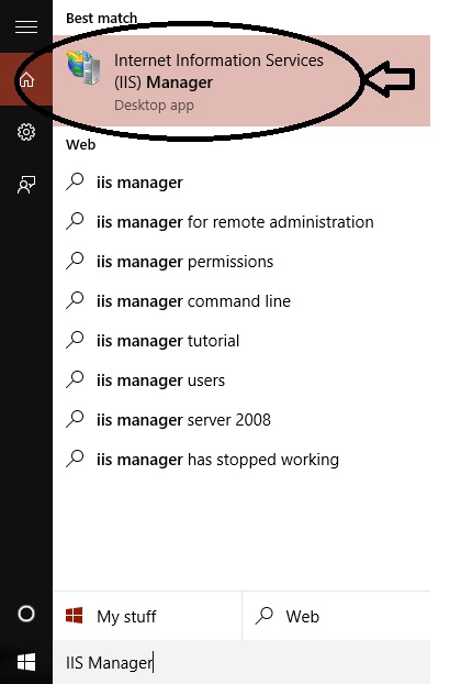
First. type “IIS Manager” into the “Search the web and Windows” box on the lower left part of the PC screen and select “Internet Information Services (IIS) Manager” from the list.

IIS_Open

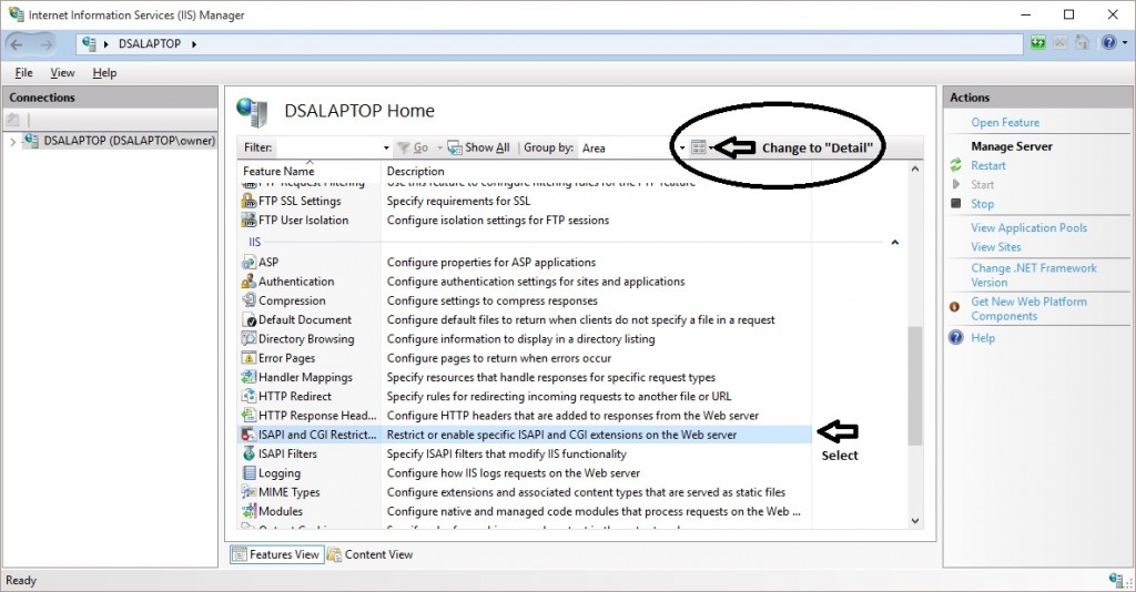
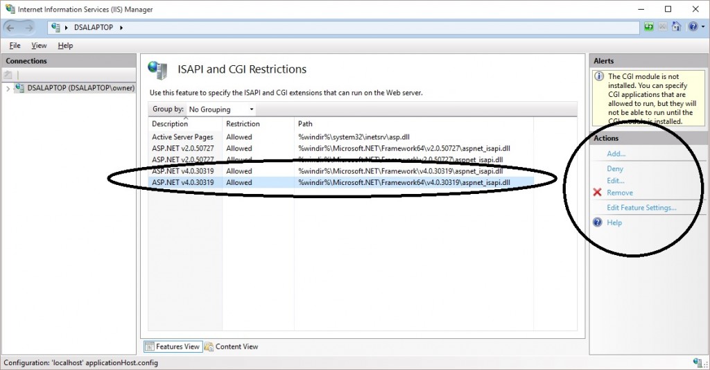
When the IIS Manager windows appears, change the view to “Detail”. Then, under the “IIS” section, select ISAPI and CGI Restrictions.

restrictions

The list that appears should include ASP.NET v4.0.30319 as shown below. The Restriction should also be set to “Allowed”. You can Add the feature if it is missing and set the restriction to “Allowed” from the “Actions” options on the right part of this windows.

allow

That’s it. With these settings, the IIS should be active and you should be able to run ASP pages locally on your PC.

Hello World! ASP Test file

Now let’s run a simple test to verify the ASP server is working. Here are my step-by-step instructions:

1. Look for a new folder called Inetpub on your hard drive.

2. Open the Inetpub folder, and find a folder named wwwroot

3. Create a new folder, call it “asp”, under wwwroot. (Any folder name will do)

4. Write the following ASP code and save the file as “helloworld.aspx” in this new folder

Hello World
 
  1.  &lt;%@ Language="VBScript" %&gt;
  2.  &lt;!--- This page should display "Hello World!" ---&gt;
  3.  &lt;!--- if ASP is available to you locally.     ---&gt;
  4.   &lt;HTML&gt;
  5.     &lt;HEAD&gt;
  6.       &lt;TITLE&gt;ASP Hello World Test Page&lt;/TITLE&gt;
  7.     &lt;/HEAD&gt;
  8.     &lt;BODY&gt;
  9.       &lt;%
  10.        Response.Write("Hello World!&lt;br&gt;")
  11.        %&gt;   
  12.       &lt;/BODY&gt;
  13.   &lt;/HTML&gt;

5. Make sure your Web server is running (see below)

6. Open your browser and type “http://localhost/asp/helloworld.aspx“, to view your first web page.
If ASP is served correctly, the browser should display:

Hello World!

Now try to open the page using the full path in the browser:

C:/inetpub/wwwroot/asp/helloworld.aspx

As you can see, in the case, the IIS is not working to serve the ASP page. Instead, the file source is displayed the same as shown in step 4 above.

Useful ASP Links

Here are some links I have found useful in learning more about ASP.

In Closing

You now have a simple reference to install a local ASP server on your PC. This should prove to be valuable for anyone developing or maintaining ASP files.

Hope you find this information useful…


Loading

Share This:
FacebooktwitterredditpinterestlinkedintumblrFacebooktwitterredditpinterestlinkedintumblr

Press Ctrl+C to copy the following code.
"