Archives for May 2015

ESP8266 WIFI dropout-proof connectivity

How to eliminate ESP8266 WIFI drop-outs

Just when it seemed like the ESP8266 was operating rock-solid, indeed running continuously for days now without resetting, or worse, fatally crashing, a sign that something was wrong appeared…

wifi

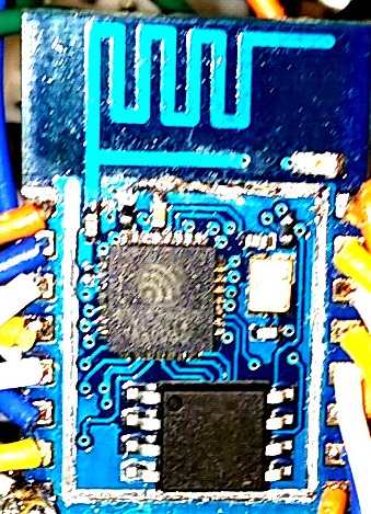
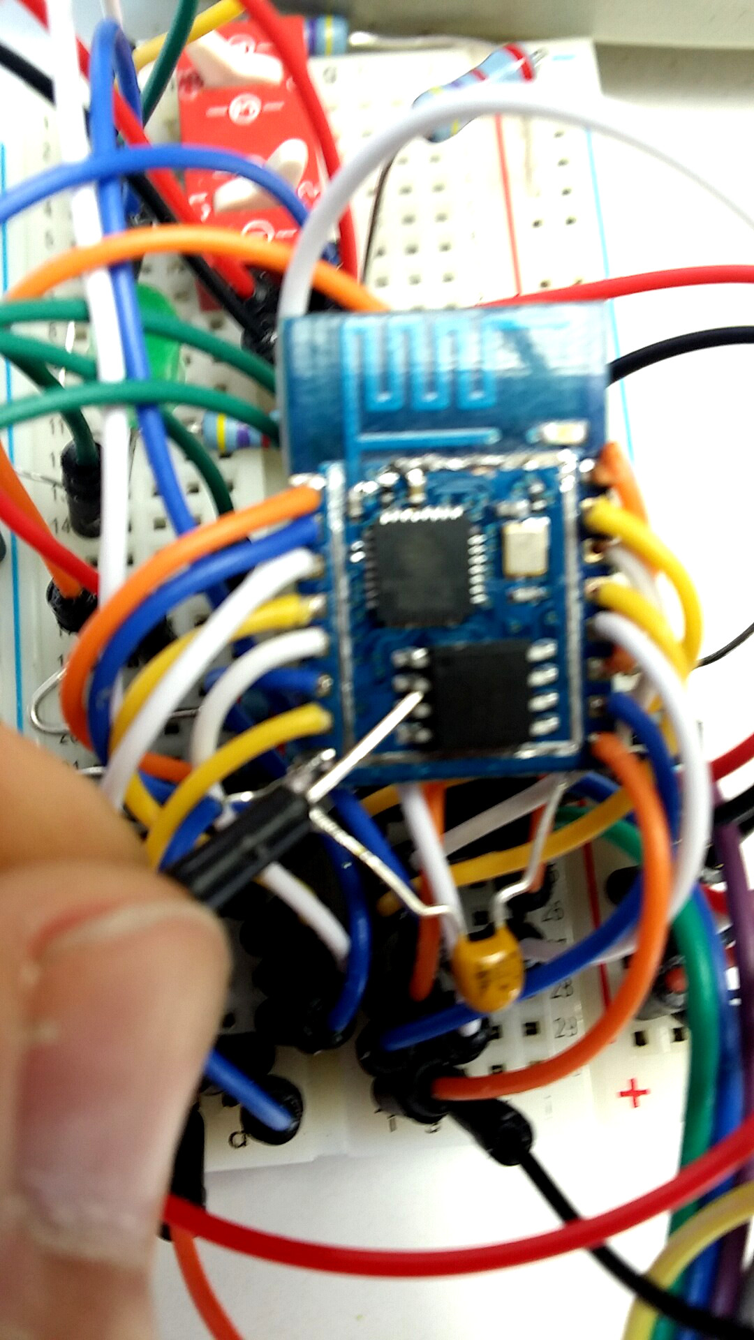
Out of the corner of my eye, a flash of light seemed to originate from the up ’till now reliably running ESP8266 based circuit. As my gaze turned directly towards the module, the blue LED started flashing. Not just once, but several times with a silent couple of seconds between illuminations…

“Uh-Ohh”, I thought, “looks like the ESP8266 is once again in a reset loop!” First thing to check was the ESP8266 web server response to a http GET request. The server did respond with a JSON string, just like it was programmed to do. And much to my surprise, the status (seconds running since last reset), indicated the module had been continuously running for days.

So why the flashing blue LED?

I noticed that sending a http GET request around the time the flashing occurs required considerable time (up to 10 seconds) before the ESP8266 returned a JSON response string. This could only mean one thing…

A WIFI Connectivity Check and Recover is Essential

The application firmware had detected a loss in WIFI connectivity and was attempting to reconnect. I had added a WIFI check to the top of the Arduino IDE loop() function. It never seemed to detect a loss of WIFI. That is, until now…

While the following code was developed using the Arduino IDE, the same check should be included for the SDK or NodeMCU code as well.

//connect wifi if not connected
if (WiFi.status() != WL_CONNECTED) {
    delay(1);
    startWIFI();
    return;
}


So the setup() function initially establishes the WIFI conection with a call to startWIFI(). The WIFI status is subsequently checked each iteration of the loop() to maintain the connection.

Fortunately, I had included some status messages in the startWIFI() function sent out the serial port just in case some troubleshooting was needed. This came in handy to confirm the root cause of the flashing blue LED.

void startWIFI(void) {
    //set IP if not correct
    IPAddress ip = WiFi.localIP();
    if( ip!= ipadd) {
        WiFi.config(ipadd, ipgat, ipsub); //dsa added 12.04.2015
        Serial.println();
        delay(10);
        Serial.print("ESP8266 IP:");
        delay(10);
        Serial.println(ip);
        delay(10);
        Serial.print("Fixed IP:");
        delay(10);
        Serial.println(ipadd);
        delay(10);
        Serial.print("IP now set to: ");
        delay(10);
        Serial.println(WiFi.localIP());
        delay(10);
    }
    // Connect to WiFi network
    Serial.println();
    delay(10);
    Serial.println();
    delay(10);
    Serial.print("Connecting to ");
    delay(10);
    Serial.println(ssid);
    delay(10);
    WiFi.begin(ssid, password);

    while (WiFi.status() != WL_CONNECTED) {
        Serial.print(".");
        delay(500);
    }
    Serial.println("");
    Serial.println("WiFi connected");

    // Start the server
    server.begin();
    Serial.println("Server started");

    // Print the IP address
    Serial.print("ESP8266 IP: ");
    Serial.println(WiFi.localIP());

    // Print the server port
    Serial.print("ESP8266 WebServer Port: ");
    Serial.println(SVRPORT);
    delay(300);
}


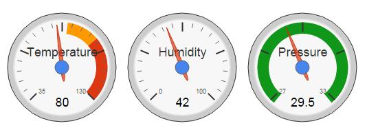
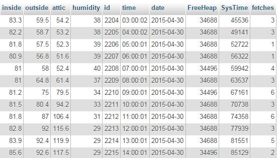
As I mentioned, the my ESP8266 web server returns status, along with sensor readings in a JSON string upon receiving http GET request. This data is logged to a mySQL database, once every hour. A CRON php script pulls the ESP8266 data and saves it to the database.

The next step

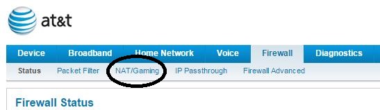
In order to assess how frequent WIFI connectivity is lost and restarted, I am going to add a static counter to my startWIFI() function. This will identify the number of times the WifFi connection was lost and reestablished since the last reset. That value will be recorded to mySQL along with the other values. It will be interesting to see how often this occurs. Once a day? Several times per hour? We shall see…

If you have had any issues maintaining WIFI connectivity, or your server stops responding to request, consider this as a solution.

I hope you find this information useful…

Update: July 5, 2015

The ESP8266 supporting my weather sensor webserver did reset 23 days ago. I took that opportunity to add a static counter to the startWIFI() function. A ThingSpeak channel has also been established to share the live results publicly.  As of this update, the Wifi connectivity was lost 537 times.

Recovery was successful every time as no ESP resets have occurred yet.

This empirical data shows the Wifi connectivity is lost on average 23 times per day.

Loading

Share This:
FacebooktwitterredditpinterestlinkedintumblrFacebooktwitterredditpinterestlinkedintumblr

A cleaner ESP8266-12 hardware setup

ESP8266 packaging issues

One of the first challenges to overcome when you get a bare module ESP8266-12 SoC is how to connect this unit to a circuit. It comes without header pins and the pin pitch is less than the standard 2.54 used on solder-less and copper breadboards. Clearly, it is not ready to use out-of-the-box like, for example, any of the Arduino options.

My first circuit used a 16-pin DIP package with short jumper wires soldered between the ESP8266 pin holes and the DIP. This assembly was then plugged directly on a solder-less breadboard. While this gave me a quick start into the ESP8266 world, the setup was messy and even worse – unstable.

Solder-less Breadboard

Disappointed and often frustrated by the poor performance of the setup, my next setup used a copper plated breadboard. The ESP8266 was mounted to the board using thin (28 AWG) bare wires. These wires were soldered between the ESP8266 through-holes and the breadboard pads. This was a vast improvement in terms of stability. I currently have a system that has been running for over 2 weeks now with no resets or system crashes. The real-time data collected with this system is displayed publicly on ThingSpeak for independent verification.

But with this setup, the tiny interface wires require a lot of time to initially assemble.

That’s where this adapter plate really shines…

Yes, it really made things easier when I stumbled upon a clean and inexpensive adapter for the ESP8266-7/12 modules. For just 28 cents (AliExpress), you get a PWB plate with pre-soldered mounting pads and a 10k pull-up connected to the chip enable (CH_PD).

A 10K resistor is also included that pulls-down GPIO15 to ground. This resistor is way to large to be of any value for that purpose. For proper boot operation, you must add a connection between GPIO15 and ground.

Finally, the fix is in – the pin labels for GPIO4 and GPIO5 have been corrected on this plate. No more confusion for that until now overlooked ESP8266-12 module design error.

ESP8266-12 adapter plate

The circuit has come together quite nicely. So far, it has proven to be a very dependable configuration. Boots without errors and flashes reliably the first time, every time. We shall see if this remains true as more the flash cycles are performed.

Fully assembled ESP8266 with adapter plate

This begs the question… Why not mount all the parts on a plate like this & eliminate the original carrier board?

A few design considerations

  • Notice the 0.1uF decoupling capacitor added close to the ESP8266 assembly. Positioning this essential capacitor there…directly across the ESP8266 VCC and Gnd pins, is absolutely critical for stable operation.

20150519_decouplingcap

  • The header pins were mounted backwards so the longer posts are facing upwards. This will be useful should it be necessary to connect female jumpers directly to any ESP8266 pin.
  • The USB to serial adapter cable connections are split between two terminal sections. The right two terminals connect USB 5V and Ground. The left two terminals, serial transmit and receive, are only used when flashing the firmware. Once deployed, the left two terminals are disconnected and the 5V and ground connections are attached to a USB cable. This supports power sourced from a USB wall or car adapter as well as a USB battery.
  • The ESP serial receive pin has a 100 ohm series resistor included from the serial transmit source. In addition, a 3.3V zener diode clamps the input voltage into the ESP8266. Many ESP8266 users omit these parts. This is not advisable. Exceeding the specified input range will likely degrade the system performance and possibly introduce hard to find latent defects! For long-term reliable operation, these common, readily available components should be included in every interface circuit.

ESP8266-schematic - serial

  • An AMS1117 voltage regulator converts the 5V to 3.3V for the ESP8266 supply. This is mounted on the breadboard copper side of the breadboard so the heat sink built into the regulator can be soldered to the board.

Regulator Heat Sink

  • To minimize instabilities from voltage ripple, two 470 uF capacitors are used, one across the 5V source and one across the 3.3V ESP8266 supply.

ESP8266-schematic - power

In Conclusion

In my experience, while cheap, feature rich and full of promise, unwanted system resets, flash failures and crashes have been the curse when working with the ESP8266.

But there is hope…

This recently introduced adapter plate, along with the hardware interface features presented here will help mitigate these undesirable outcomes.

Hope you find this information useful…

Loading

Share This:
FacebooktwitterredditpinterestlinkedintumblrFacebooktwitterredditpinterestlinkedintumblr

8 ESP8266 analog inputs for 22 cents

Want More Analog Inputs?

Do you have a project needing more than one analog input? If your using an ESP8266, that would seem to be a problem as it only offers a single input. Before you commit to using an Arduino, Spark Core, Raspberry PI or other higher priced micro-controller, one with multiple analog inputs, consider this…

ESP8266image

Adding an 8-1 multiplexer chip to your ESP8266-07 or -12 circuit can expand your system capability from one to eight analog inputs.  I recently tested this out, using a 74HC4051 CMOS analog multiplexer component I got from an AliExpress supplier.

The cost?

$2.19 for 10 chips, or $0.22 per chip.

They are available in a 16-pin DIP package  with 2.54 pitch for easy use with a solder-less breadboard.muxpicSo what’s the downside? Well, selecting one of the 8 analog inputs will require 3 GPIO pins. For many applications, that should not pose a problem when using the ESP8266-07 or -12. These versions have 7 easily accessible GPIO pins available, leaving you with 4 GPIO pins for any digital input or output requirement after adding the 8 analog inputs.

Here is the circuit I used to test this configuration:

ESP8266-schematic - amux-test_rev1

The left side of this drawing is the standard circuit I have been using for all of my ESP8266 projects. A typical USB to serial adapter is used when developing and flashing the circuit. When deployed, I use a USB plug with a wall adapter to provide a 5V source, without the Tx/Rx signals.

The analog multiplexer is controlled by 3 GPIO pins; 14,12 and 13. Setting the states of these 3 digital outputs determine which analog input will be measured.

GPIO14 GPIO12 GPIO13
A0 0 0 0
A1 0 0 1
A2 0 1 0
A3 0 1 1
A4 1 0 0
A5 1 0 1
A6 1 1 0
A7 1 1 1

The sketch used to test this circuit was developed using the ESP8266 Arduino IDE.

The serial output loops through each analog input, setting the multiplexer and reading an input every 2.5 seconds. The sketch also behaves as a web server. All 8 analog values can be retrieved in a single JSON string returned from an http GET request.

ESP8266 ADC Performance Evaluation

Using this circuit and software, I proceeded to collect some data to characterize the ESP8266 analog input range. First, the multiplexer selector was verified by connecting each input to ground and verifying the Analog count returned was 0. Likewise, each input was connected to 3.3V with a reading of 1024 returned when reading the ESP8266 ADC pin.

All good so far…

Then I connected the A0 input to a variable resistor to vary the input voltage voltage.

ESP8266-schematic - amux-Test-Circuit-updated

At the same time, an external Digital Multimeter (DMM) was used to monitor the voltage applied to the ESP ADC input via the multiplexer. For each voltage setting, I recorded the DMM reading and the ADC count returned from the ESP8266. It would have been great to have a calibrated bus controlled DMM to automate this process, but for the purpose of this DIY home project, I simply entered the values into an excel spreadsheet manually.

Thirty-seven voltage settings were applied in the range between 0.2V and 1.2V. Any voltage below 0.2V returned a 0 bit count while voltages above 1.2V returned 1024. I observed approximately 10 values returned from the ESP8266 for each voltage applied and recorded the high and low bit count readings for these measurements. The average of the high and low reading was then used to chart the results.

ESP8266 ADC voltage vs bit count

As you can see, the results were reasonably linear. But there is compression at the voltage extremes. For practical use, I would not use the non-linear ends, limiting the voltage swing from 0.25 to 1.15 V, a 0.9 V range.

The data collected can be reduced to a “best fit” equation. This would provide a method of converting the raw ADC value count to a voltage. Ideally, a data point should be collected for each ADC count value. The equipment I used for this exercise was not calibrated or accurate enough to do this. Given these uncertainties in my test setup, I am not sure if the variances I observed for consecutive readings…and they did vary somewhat…was result of the input voltage source or the ESP8266 ADC.

Still…with the data I had collected, the formula was determined to be:

Vain = (0.94* ADCcount + 200) mV

The slope was determined by dividing the voltage difference by the ADC count  difference at each end of the voltage range. And 200 mV, the intercept, is the voltage when the ADC started reporting 0 for the count.

While there does not appear to be a definitive specification, this is consistent with what I have read regarding the ESP8266. The 10-bit ADC resolution is supposed to be approximately 1 mV with a 1 V range.

Resolving Sensor Incompatibilities

So what can you do if your sensor range is outside the ESP8266 0.2 to 1.2 V window?

Scaling of course.

This can be accomplished passively, using a resistor divider, or actively, with the addition of an op-amp. The interface of choice would be an active op-amp based circuit.

For example, suppose your sensor has a 0-5V range. This would need to be scaled to fit in the ESP8266 0.2 to 1.2 V input range. Obviously, resolution will be compromised as we go from a larger range to a smaller one, but it can be done. And with a single power supply.

ESP8266 Analog Input Voltage Level Shifter

Resistor values calculated here. The 24K/1K resistor divider supplies the 0.2V offset with the gain set for the 1.15 V output with a 5V maximum input applied. This circuit would need to be modified for your specific sensor voltage range.

In summary

So there you have it. Eight analog inputs measured using a single ESP8266 SoC. Possible simply by adding a 22 cent chip.

And I got to mention one more option. Just in case you want even more…

A 16 channel version of the multiplexer is also available (74HCT4067). That’s a whole lot of analog!

I hope you find this information useful.

Loading

Share This:
FacebooktwitterredditpinterestlinkedintumblrFacebooktwitterredditpinterestlinkedintumblr

My ESP8266 Controlled Temperature Sensors now on ThingSpeak

Now that my ESP8266 controlled sensors have been on-line and are now reliably running, the next step was to push some of the data up to ThingSpeak. Up to now, I had been saving the readings exclusively in my host server account’s mySQL database.

And now the temperature readings are also pushed up to ThingSpeak, once every hour.

But not by the ESP8266 micro-controller. No…I have discovered that the stability of the ESP8266, at least at this time, is linked to the frequency of accessing it through http client GET requests. Access to my ESP8266 is tightly controlled. It has to be. I’ve written about structuring a stable ESP8266 Arduino IDE sketch loop() in another post. This may be helpful if you are have issues with the ESP8266 reliability.

The video created to describe the ThinkSpeak channel breaks down the unique methodology I’ve used to move sensor readings up to ThingSpeak.

You can check out the real-time data now visually served to the world on my new ThingSpeak channel. I’m hoping there is something unique about the method used to upload the readings and the eye-catching displays that could be of value to someone. Something not found on any other of the many channels displaying similar data.

Setting up the channel was easy. ThingSpeak is a free platform serving first as a repository database, like mySQL, to store data read from your Internet of Things (IoT) gadgets.

Once you have a periodic data feed to ThingSpeak, the platform can execute actions based on the data. It also provides a simple API to take some of the burden off your micro-controller. Here’s highlights of what ThingSpeak can do for you:

  • ThingTweet – This service provides a simple API for your IoT thing to post Twitter messages.
  • React -Performs whatever action you need when the data in your channel meets your custom set condition. Some obvious examples:
    • Turn light on when proximity sensor detects someone in room
    • Water lawn when moisture detector reaches dry threshold.
    • Turn heater on when temperature drops below certain reading.
  • TalkBack – API that has device execute queued commands. The queue is loaded in ThingSpeak. Then the device request a command, and performs an action based on the command it gets from the ThingSpeak queue. I have not thought of an application for this yet, but I’m sure you might find some from ThingSpeak.
  • TimeControl – Allows you to setup ThingHTTP or ThingTweet requests a a predetermined time. There are many ways to do this, but using ThingSpeak could reduce the burden placed on your device or other element in your IoT ecosystem.

Temp Humidity Baro-Pressure

That’s it for now. Keep your creative juices flowing. I may add my humidity and barometric pressure readings to the initial ThingSpeak soon – in a 3-gauge display window. Like you see above. Being in the US, my temperature is in Fahrenheit and the pressure is inches of mercury. What will you do next?

I hope you find this information useful…


Loading

Share This:
FacebooktwitterredditpinterestlinkedintumblrFacebooktwitterredditpinterestlinkedintumblr

What to do when ESP8266 will not flash

Are your ESP8266 flash attempts failing? Or perhaps not working at all anymore? Getting that annoying “Invalid head of packet” exception?

I have. Very frustrating…

And there aren’t many answers to be found on-line. What really got me steaming was the “Fatal error” messages at 115200 baud after I thought the flash completed properly. I have been there.

Over and over again…

Just when I was ready to give up…after many, many flash attempts, a flash will actually succeed. You think everything is good again, but the problem just keeps coming back…

What is wrong? Is this just a cheap Chinese trinket? An illusion of the Holy Grail? The ESP8266 specs look great. With such a cheap price tag that sucked you in? Or is there something your doing wrong?

Here is what I have found to be the problem…

And yes, there is a solution.

What many of us have experienced wit these ESP8266 modules, especially those that like to tinker and flash often, is the very low flash cycle count that the memory chips shipped with many of these modules will tolerate before failing. In my experience, flash failures start after only 20 flash cycles or so.

Then it only gets worse from that point on.

The good news is that the memory chips are not difficult to replace. And they are cheap when you order them with free shipping from the slow boat from China. You should be able to find them on AliExpress or your other favorite source. Here are some recent quotes for the different chips found on ESP8266 modules:

Description Flash ID Size Recent Price (USD)
1 Winbond W25Q40 1340ef 512 KByte 0.32 each 7.85 (per 25)
2 GigaDevice GD25Q40 1340c8 512 KByte 0.32 each 7.85 (per 25)
3 Winbond W25Q32 1640ef 4 MByte 0.42 each 4.14 (per 10)

From looking at the firmware binary header, it looks like the flashes are made for a 512 KByte flash chip (byte 3 upper 4 bits are 0). This would suggest that CURRENTLY, all that is used with the ESP8266 is 512 KBytes.

That is what I am using to replace the flash chip when they start to fail intolerably. I have recently replaced a 4MByte flash chip with a 512 KByte component, it worked flawlessly. With the same amount of space free for the application. You can clearly see that the ESP8266 SDK indicates the maximum firmware size as 512 KBytes.

I have been using the ESP8266-12 modules. The only added step needed for flash chip replacement from an ESP8266-01 is that the golden metal case must be removed to gain access to the SPI memory chip. This is not impossible, you just have to take your time, be patient, and careful.

I use a razor blade to pop the cover off. You just have to score the crease where the metal case meets the PCB. Only do this on the edge that is away from the PCB antenna. This minimizes the risk of damaging something. Eventually, the blade will breach the case bonding. When it starts to give, the rest of the cover will soon separate from the module – cover removed!

Remove ESP8266-12 cover

Take it slow so you do not cut yourself, damage the module, or snap the blade. I use a blade with a safety cover. It only require 5-10 minutes to remove the cover in this manner. I have done it to two modules so far with no damage incurred. I have seen some folks use a heat gun to remove the cover. This is too risky in my opinion.

ESP8266-12 Cover off

The SPI memory chip will be the obvious 8-pin device. Not to worry. While the ESP8266 would be very challenging to remove, not so with the memory chip. The pins are larger than the ESP8266, making them easier to remove. Just spot apply a hot soldering iron tip to each pin with a pointed object used to lift the pin while the heat is applied. One pin at a time. I found that a breadboard jumper to work for this purpose.

ESP8266 flash memory remova

When you have the chip removed and are ready to install the new chip, remember to use the same orientation. A small dot on the chip identifies pin one. Just make a note before removing the old chip for reference. And, obviously, limit the amount of heat applied to each pin.

I am currently using my replacement SPI chips for development and have a decent supply on hand (only 32 cents per chip) to focus on project development, free from the agony of squandering time over recurring flash failures.

I’ll give an update when the replacement chips start to fail to flash. Hopefully, there will be an improvement from the original chips. More flash cycles before the first failure. We shall see. But I can live with it knowing a chip swap will chase this demon away, at least for a while.

Hope that you find this information useful…

Loading

Share This:
FacebooktwitterredditpinterestlinkedintumblrFacebooktwitterredditpinterestlinkedintumblr

Using Javascript AJAX to read ESP8266 data

Okay, so you got your ultra low-cost ESP8266 workhorse setup to read some sensors. And you have an awesome webpage built to visually display the readings. But how do you get the data from the ESP8266 to your website?

PHP and/or Javascript are the two most popular methods. I have used both.

This writing presents a simple Javascript solution. I have also posted an approach to this task using PHP here.

My need came about while developing a mobile app to monitor and control devices in my home. My personal IoTs. Using the Apache Cordova API with the Eclipse IDE. I was developing my App with just HTML, CSS, and JavaScript. Yet it will compile and install onto my Android device like any other application. It is my understanding that the same code can be built into an iOS App as well…but…being strictly a PC user, I have not attempted that.

And let’s get back to using Javascript to pull information from an ESP8266 based web server.

The thing was, I needed to pull my weather, sprinkler, garage and other sensor data from the ESP8266 circuit that monitors these devices to my App. I also wanted maintain control of the data. To be free from a cloud middleman such as ThingsSpeak.

With this in mind, we have two sides to this solution; The micro-controller unit (MCU), which is the ESP8266 in this case, and the client App. The ESP8266 must read all the devices connected to it and then send this data, on request, to the App client. The preferred format is either JSON or XML.

I use JSON strings.

Here is an example of a short function that can be used to create a JSON string in an Arduino IDE sketch. It is critical to include the http header information provided in this example. The header authorizes your domain, allowing the Javascript AJAX to retrieve the ESP8266 http response.

Here is the Javascript with AJAX code used to request a JSON string from the  ESP8266, decode it, and display the values on a webpage.

function updateWeatherSensorData() {
    requestURL = "http://myrouterdomain.com:9999/?request=GetSensors";
    if ( typeof updateWeatherSensorData.timeout == 'undefined' ) {
        // It has not... perform the initialization
        updateWeatherSensorData.timeout = 0;
    }
    //Get Weather Sensor Value
    $.ajax({
        url: requestURL,
        error: function(error){
            if(updateWeatherSensorData.timeout++ <10) {
                setTimeout(updateWeatherSensorData, 1000);
            }
            else {
                updateWeatherSensorData.timeout = 0;
            }
        },
        success: function(thedata){
            $("#baro").html(thedata.B_Pressure + " inHg");
            $("#tempIn").html(thedata.DS_TempInside + " F");
            $("#tempOut").html(thedata.DS_TempOutside + " F");
            $("#tempAttic").html(thedata.DS_TempAttic + " F");
            $("#humidity").html(thedata.DH_Humidity + " %");
            updateWeatherSensorData.timeout = 0;
        },
        timeout: 7000 // sets timeout to 7 seconds
    });
}


I am assuming you have a domain name pointed to your router and your router is configured to port forward internet requests. For reference, here is how to set this up.

How this Javascript code works:

First, the URL used to send the http GET request to the ESP8266 is defined. This URL has 3 parts

  1. The domain name: http://myrouterdomain.com
  2. The port your ESP8266 web server is listening on: 9999
  3. The request string recognized by the web server: /?request=GetSensors

Then we need to define a timeout property for this function. The timeout is actually used to store the number of attempts to retrieve the JSON from the ESP8266 before successful.

And now, the AJAX call. As you can see, the code is structured like a JSON string, with 4 keys and 4 values:

  1. url: This defines where to send the request.
  2. error: In case the request fails, the call is repeated, up to 10 times
  3. success: When successful, the webpage elements with the indicated ID are filled with the value retrieved from the ESP8266
  4. timeout: Up to 7 seconds is allowed before a timeout error is declared.

That’s it! This is what I have been using to retrieve JSON strings from my ESP8266 using an AJAX call.

In Summary

Here are a few closing thoughts of my observations for your information…

  • The error handling is essential. This call fails frequently, perhaps every 2 or 3 requests.
  • Most of the time, the error is because a blank string is filled from this call. I do not know if that is an ESP8266 issue or a problem with AJAX.
  • The timeout was set to 7 seconds because I have seen it take up to 4 seconds to get a response.

Hope you find this information useful for your ESP8266, Arduino and other MPU projects.

Loading

Share This:
FacebooktwitterredditpinterestlinkedintumblrFacebooktwitterredditpinterestlinkedintumblr

Using DDNS with port forwarding to access Internet connected things

Setting up the mechanism to access your home network from the Internet is straightforward and often available as a free service.
You could simply determine the IP address your Internet service provider (ISP) has assigned and use that address from anywhere you happen to be.

This is quick and easy.

Problem is…your ISP may change this address at any time, and if you are away from the home network, it will be difficult to determine the updated address. So you become cut off from your home network.

To resolve this issue, a DDNS (Dynamic domain name server) account is needed. A DNS simple resolves a domain host name to an IP address. Using a dynamic DNS updates the IP address that the domain name points to whenever it changes…automatically.

DDNS Providers

There are both free and fee based DDNS accounts available. The following lists some of the options currently available. If you don’t like any of these, just do a google search for DynDNS providers.

Name Website Cost Description
1 DynDns http://dyn.com/dns/ $25/year One of oldest and well-known providers
2 Duck DNS https://duckdns.org/ FREE Hosted on Amazon EC2
3 NO-IP http://www.noip.com/free FREE Advanced paid plans offered
4 DtDNS https://www.dtdns.com/ FREE Advanced paid plans offered
5 yDNS https://ydns.eu/ FREE Another option
6 FreeDNS https://freedns.afraid.org/ FREE Yet another option

The instructions for setting up these accounts are typically quick and simple. You pick a domain name, one of your choice, and this name will likely have a suffix appended to it. This part is selected by the provider. This is a very small price to pay for a FREE service. Then this name gets synchronized with your current network IP. That’s it.

Setting up the router for port forwarding

You will undoubtedly have more than one device to connect from your local network to the Internet. But there is only one IP assigned to your network. So how can the traffic initiated from your DDNS domain name, which resolves to your Internet IP, know which device on your network to deliver the  message to?

Simple-Ports…

Think of the IP for your Internet connection as a post office and the ports as the individual boxes.

The connection to your device will almost certainly use Transmission Control Protocol (TCP). And TCP identifies the destination by port number. The valid range is 0 to 65535. So for each device on your local network, a port needs to be assigned for delivery of packets from the network.

The key to making this work is to configure your router to forward packets from the Internet to the intended recipient, that is, the destination port. Hence, the name port forwarding.

While this is not too difficult to set up, the step-by-step directions for port forwarding are unique for each router. That is simply because router firmwares are all different. The setup is typically found in the firewall settings. Here is how to do in with a D-Link DIR-625 router. Just 3 simple steps. 1-2-3… Your router should have similar options for setting up port forwarding:

Port forwarding a D-Link DIR-625

1. First, select the ADVANCED menu item from the initial router screen.

D-link Port Forwarding 1


2.Next, click on the PORT FORWARDING tab.

D-Link Router Port Forwarding


3. Now all you need to do is identify your local network device by IP, assign a port to it, and save your configuration.

Port Forwarding with a D-LINK Router


My ISP is AT&T U-verse. Setting up the router they provide for port forwarding was not so obvious, at least at first glance. Since this is such a popular home router, I am also providing port forwarding setup instructions here.

Port forwarding an AT&T NGV-589

Now the AT&T router configuration for port forwarding is a bit more tedious. I’ve broken it down into the following 8 steps.

1. Access your router’s main web portal page and select the Firewall tab.

AT&T NVG589 router port forwarding setup

2. Select NAT/Gaming.


AT&T NVG589 router port forwarding setup

3. You’ll then be instructed to enter the router access code.

portforwardatt3

4. Now, click on the “Custom Services” button.

portforwardatt9

5. Alas, we have now arrived at the screen to identify the port! Here, enter a name for your device and the port number(s) you with to assign to your device. In this illustration, I have assigned port 9701 to my second ESP8266. Click on the Add button to include this port/device(Service Name) to the router’s list.

portforwardatt6

6.The entry should now appear in the Service List. Next step is to click on the “Return to NAT/Gaming” button.

portforwardatt10

7. Now, Select the Service that was just defined (ESP8266-2) and the needed by device. You should see your needed by device in the drop-down list by the IP that it has been assigned. The device MAC is also shown on this list. Click on the “Add” button to complete the port forwarding setup for your device.

portforwardatt11

8. Your router’s “Hosted Applications” list should now display the device that you have just configured for port-forwarding.

portforwardatt12

NOTE regarding the AT&T NVG589: I have experienced issues with my router which did not allow me to access devices locally. While not universal among all users, I am not the only one to have this problem. This appears to be an issue with the router’s firmware, which did not appear to have a solution.

My answer was to use my own router and put the AT&T router in pass-through mode. If anyone has experienced similar problems, that would be my recommended solution. While using 2 routers was not particularly appealing, it does work. Allowing you to move on to other things…

In Summary

This should de-mystify port forwarding. Some routers require more steps than others to accomplish the same thing. Simple, yet this is an essential step to connecting your things to the internet.

Hope you find this information useful…


Loading

Share This:
FacebooktwitterredditpinterestlinkedintumblrFacebooktwitterredditpinterestlinkedintumblr

Using php to read ESP8266 data

While I have published another post, covering this topic using a Javascript AJAX call, using php has unique attributes, and must be used in certain cases. Please refer to that post is anything here is unclear.

In my case, I needed to periodically save my home weather sensor values into a mySQL database. While this can be accomplished with a CRON triggered php server side script, the client sided AJAX will not work. So here is my php script to pull data from my ESP8266 and save the values in a mySQL database.

<?php

include("access.php");
session_start(); //We need to have static variables
$Esp8266SensorURL = $esp8266_9702_GetSensors_URL;

//---------------------------------------------------------------------
//Functions
//---------------------------------------------------------------------
//
//---------------------------------------------------------------------
//Name: get_fcontent( $url, $javascript_loop = 0, $timeout = 5 )
//Function: CURL that gets URL contents
//Parameter 1: $url - URL to retrieve
//Parameter 2: $javascript_loop - IDK, this function pulled from internet
//Parameter 3: $timeout - IDK, this function pulled from internet
//---------------------------------------------------------------------
function get_fcontent( $url, $javascript_loop = 0, $timeout = 15 ) {
    $url = str_replace( "&", "&", urldecode(trim($url)) );
    $cookie = tempnam ("/tmp", "CURLCOOKIE");
    $ch = curl_init();
    curl_setopt( $ch, CURLOPT_URL, $url );
    curl_setopt( $ch, CURLOPT_COOKIEJAR, $cookie );
    curl_setopt( $ch, CURLOPT_FOLLOWLOCATION, true );
    curl_setopt( $ch, CURLOPT_ENCODING, "" );
    curl_setopt( $ch, CURLOPT_RETURNTRANSFER, true );
    curl_setopt( $ch, CURLOPT_AUTOREFERER, true );
    curl_setopt( $ch, CURLOPT_SSL_VERIFYPEER, false ); # required for https urls
    curl_setopt( $ch, CURLOPT_CONNECTTIMEOUT, $timeout );
    curl_setopt( $ch, CURLOPT_TIMEOUT, $timeout );
    curl_setopt( $ch, CURLOPT_MAXREDIRS, 10 );
    $content = curl_exec( $ch );
    $response = curl_getinfo( $ch );
    curl_close ( $ch );

    if ($response['http_code'] == 301 || $response['http_code'] == 302) {
        ini_set("user_agent", "Mozilla/5.0 (Windows; U; Windows NT 5.1; rv:1.7.3) Gecko/20041001 Firefox/0.10.1");

        if ( $headers = get_headers($response['url']) ) {
            foreach( $headers as $value ) {
                if ( substr( strtolower($value), 0, 9 ) == "location:" )
                    return get_url( trim( substr( $value, 9, strlen($value) ) ) );
            }
        }
    }

    if ( ( preg_match("/>[[:space:]]+window\.location\.replace\('(.*)'\)/i", $content, $value) || preg_match("/>[[:space:]]    +window\.location\=\"(.*)\"/i", $content, $value) ) && $javascript_loop < 5) {
        return get_url( $value[1], $javascript_loop+1 );
    } 
    else {
        return array( $content, $response );
    }
}

//---------------------------------------------------------------------
//Name: getEsp8266Sensor($getUrl,$update,$k)
//Function: Gets value from ESP8266 (Return last value if 0)
//Parameter 1: $getUrl - ESP8266 URL that returned JSON with sensor values
//Parameter 2: $update - if "Y", get JSON from ESP8200, else use last JSON
//Parameter 3: $k - key to retrieve value of (key:value)
//---------------------------------------------------------------------
function getEsp8266Sensor($getUrl,$update,$k) {
    if($update=="Y") {
        $_SESSION['fetches']=0;
        $status[0]="";
        ob_start();
        while((substr($status[0],0,1)!='{')&&($_SESSION['fetches']<20)) {
            $status=get_fcontent($getUrl);
            $_SESSION['fetches']=$_SESSION['fetches']+1;
            ob_flush();
            sleep(5);
        }
        $_SESSION['jsonstr'] = $status[0];
    }
    if($_SESSION['fetches']<20) {
        $status_array = json_decode($_SESSION['jsonstr']); //Decode json
        foreach($status_array as $key => $value) {
            if(strstr($key,$k)) {
                $val = $value;
            }
        }
    }
    else {
        $val=0;
    }
    //return last value if current value is 0
    if($val!=0) {
        return $val;
    }
    else {
        if(strstr($k,"DS_TempInside")) return $last_in;
        if(strstr($k,"DS_TempOutside")) return $last_ou;
        if(strstr($k,"DS_TempAttic")) return $last_at;
        if(strstr($k,"DH_Humidity")) return $last_hu;
        return $val;
    }
}

//Insert "spaces" spaces
function insertSpace($spaces) {
    for ($cnt=0; $cnt<$spaces; $cnt++) {
        $sp .= "&nbsp";
    }
    return $sp;
}

//---------------------------------------------------------------------
//Connect to database
//---------------------------------------------------------------------

$link = mysqli_connect("localhost", $mysqlUser, $mysqlPass, $mysqlUser);
if (mysqli_connect_error()) {
    die("Could not connect to database");
}
//---------------------------------------------------------------------
//Get latest values from database
//---------------------------------------------------------------------
$query = "SELECT * FROM temperature ORDER BY id DESC LIMIT 1";

if($result=mysqli_query($link, $query)) {
    $row = mysqli_fetch_array($result);
    $last_id = $row['id'];
    $last_in = $row['inside'];
    $last_ou = $row['outside'];
    $last_at = $row['attic'];
    $last_hu = $row['humidity'];
}

//---------------------------------------------------------------------
//Get Sensor Data
//---------------------------------------------------------------------

//----------------------------------------
//-----Get current LOCAL time
//----------------------------------------
$now = time();
date_default_timezone_set('America/Los_Angeles');
$localtime_assoc = localtime($now, true);

//Time
$now_hr = sprintf('%02u',$localtime_assoc['tm_hour']);
$now_mn = sprintf('%02u',$localtime_assoc['tm_min']);
$now_sc = sprintf('%02u',$localtime_assoc['tm_sec']);
$now_tm = $now_hr.":".$now_mn.":".$now_sc;

//Date
$now_yr = $localtime_assoc['tm_year']+1900;
$now_mo = sprintf('%02u',$localtime_assoc['tm_mon']+1);
$now_dy = sprintf('%02u',$localtime_assoc['tm_mday']);
$now_dt = $now_yr."-".$now_mo."-".$now_dy;

//Get Temperatures
$temp_in = getEsp8266Sensor($Esp8266SensorURL,"Y","DS_TempInside");
$temp_ou = getEsp8266Sensor($Esp8266SensorURL,"N","DS_TempOutside");
$temp_at = getEsp8266Sensor($Esp8266SensorURL,"N","DS_TempAttic");

//Get Humidity
$temp_hu = getEsp8266Sensor($Esp8266SensorURL,"N","DH_Humidity");

//Get Free Heap and ms since ESP8266 started
$temp_hp = getEsp8266Sensor($Esp8266SensorURL,"N","SYS_Heap");
$temp_tm = getEsp8266Sensor($Esp8266SensorURL,"N","SYS_Time");

//Insert a record into mySql
$query = "INSERT INTO `temperature` (`inside`,`outside`,`attic`,`humidity`,`time`,`date`,`FreeHeap`,`SysTime`,`fetches`)
VALUES('".$temp_in."','".$temp_ou."','".$temp_at."','".$temp_hu."','".$now_tm."','".$now_dt."','".$temp_hp."','".$temp_tm."','".$_SESSION['fetches']."')";
//Report Results
if ($result=mysqli_query($link, $query)) {
    echo('<br>Success<br>');
}
else {
    echo('<br>Failed<br>');
}

?>

Now let’s break this down.

include("access.php");
$Esp8266SensorURL = $esp8266_9702_GetSensors_URL;

The included “access.php” file contains definitions for my URLs used to access my home devices. Maintaining these in a separate file keeps things tidy and hidden. The variable $esp8266_9702_GetSensors_URL is assigned in the access.h file to my ESP8266 that implements a web server listening on port 9702.

session_start(); //We need to have static variables $Esp8266SensorURL = $esp8266_9702_GetSensors_URL;

session_start() enables the use of static variables

function get_fcontent( $url, $javascript_loop = 0, $timeout = 15 )

This function retrieves the contents returned from an URL, using CURL.

function getEsp8266Sensor($getUrl,$update,$k) {
    if($update=="Y") {
        $_SESSION['fetches']=0;
        $status[0]="";
        ob_start();
        while((substr($status[0],0,1)!='{')&&($_SESSION['fetches']<20)) {
            $status=get_fcontent($getUrl);
            $_SESSION['fetches']=$_SESSION['fetches']+1;
            ob_flush();
            sleep(5);
        }
        $_SESSION['jsonstr'] = $status[0];
    }


Now this is the meat of this method. The function getEsp8266Sensor() mechanizes the process of retrieving values from a JSON string returned from an ESP8266. Since a single GET request returns a JSON string that contains all the sensor values, only one request is needed, the first one. The “$update” parameter is set to “Y” from the caller to perform the GET request. The GET is declared a success if the first character (after the header) returned is “{“, the start of the expected JSON string.

I have observed this request to fail sometimes, which is why it is put in a while loop, allowing up to 20 retries. Since one of the values stored in the mySQL is the number of GET requests required before a successful attempt, I have data to characterize the failure rate. After running this script 3 times per hour for a few days now, a maximum of six attempts before success have been recorded. Twenty retries were set to provide some margin. I’ll be reviewing the data as more run time is accumulated.

Notice the ob_start() and ob_flush() statements. This was necessary to clear out the buffers from the last GET request. Without these, the request often failed continuously, regardless of how many retries were attempted.

The session variable $_SESSION[‘jsonstr’] saves the returned JSON string for subsequent calls to this function, when a request is not needed.

The rest of the function simply decodes the JSON string and extracts the requested key value.

The code snippet below retrieves the latest values stored in the database.

//---------------------------------------------------------------------
//Get latest values from database
//---------------------------------------------------------------------
$query = "SELECT * FROM temperature ORDER BY id DESC LIMIT 1";

if($result=mysqli_query($link, $query)) {
    $row = mysqli_fetch_array($result);
    $last_id = $row['id'];
    $last_in = $row['inside'];
    $last_ou = $row['outside'];
    $last_at = $row['attic'];
    $last_hu = $row['humidity'];
}

These values are used if no valid values are received from the ESP8266 during the http GET transaction.

I leave the rest of the code up to you to understand. It is all very straightforward stuff.

Here is an extract from the data stored in mySQL. The data is recorded every hour. This slice is from 3 am to 2 pm April 30,2015. As you can see, the temperatures bottomed at 6 am and the worst case performance for the software was at 9 and 11 am when 6 GET requests were required before it was received successfully.

temperature sensor database

Wow, things really got toasty in my attic that day! 119.9 F at 1 pm.

Hope you find this information as useful to you as it has been to me. Until next time…

Loading

Share This:
FacebooktwitterredditpinterestlinkedintumblrFacebooktwitterredditpinterestlinkedintumblr