Internet of Things

USB LAMP Web Server Part 3 – Adding mySQL Server

phpmysql2

A web server is certainly not complete without a database server. Currently, the one-source server of choice is mySQL. At first, adding this database server to my Linux setup update appeared to be simple and straight-forward. Just add another package to the Puppy Linux installation and restart – instant mySQL server capability. But then I soon found that it was not going to be that simple.

Still, after persistent effort to overcome several patience-trying obstacles, the installation was finally complete. Presented here are the successful steps to adding mySQL Server, without having do deal with the problems. And for those who do not want to go through all the setup steps, a Linux session save file is included with this post.

Simply replace your existing save file with this one and you will be 99% complete with a web server that supports both php and mySQL server. Here it is. You can also refer to the Quick and Easy section of this post minimal installation steps.

But if you would like to understand the steps to installing  mySQL on the USB Puppy Linux setup, read on. Now let’s add the mySQL server to the USB LAMP web server installation from part 2 of this series.

Adding mySQL Server to the USB Web Server

IMPORTANT: The installation of mySQL Server will corrupt the save file. This will make it impossible to shut-down or start the USB Puppy Linux. Prior to proceeding, copy the save (*.sfs) file, located in the root USB directory (when viewed from Windows OS). It will be needed later to restore the Linux installation.

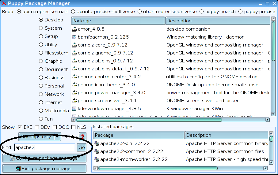
Start the USB installed Precision Puppy Linux from part 2. Then launch the Puppy Package Manager. In the search window (Find), enter “mysql”.

mysql_svr1

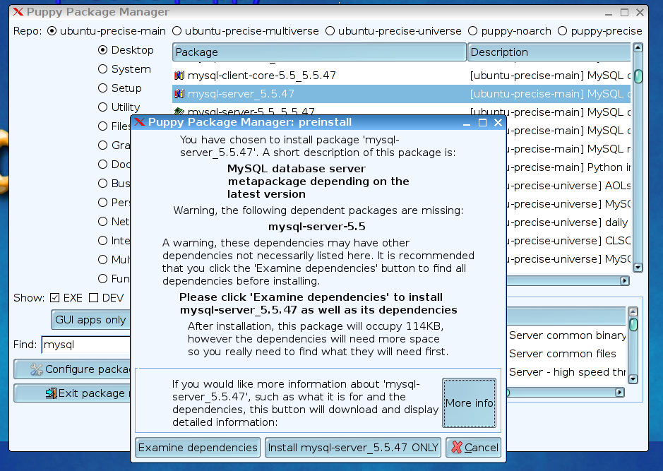
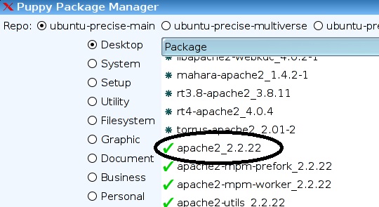
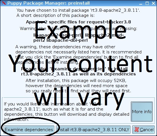
From the list of results, select mysql-server-5.5-47 metapackage.

Then click on “Examine dependencies”.

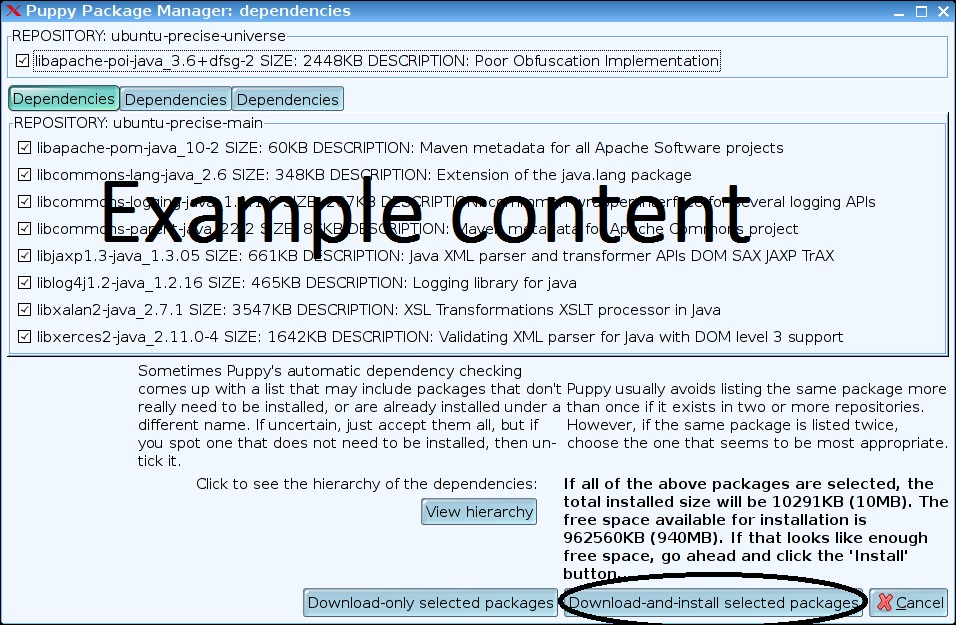
When a window pops up, click on the “Download and install selected packages” button.

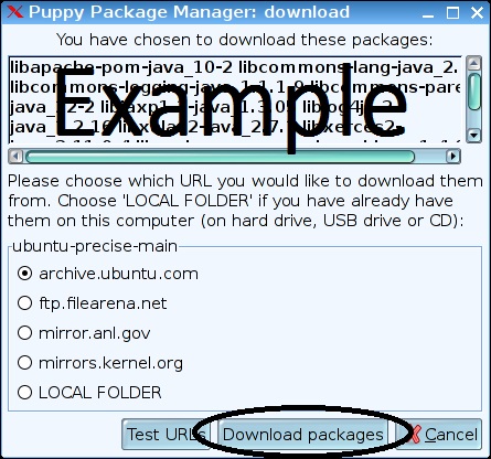
Then click on “Download packages”.

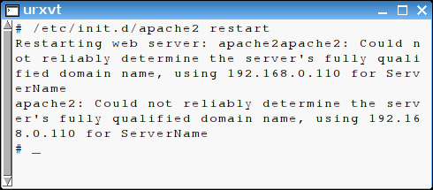
After the installation finishes, the following prompt appears:

mysql_svr5

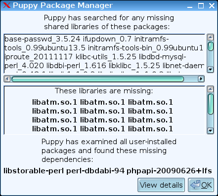
In order to add  the missing library, first close and then re-opening the Puppy Package Manager.

This time, enter “libatm” in the find input. You will probably only find one results from searching all the repositories, “libatm1_2.5.1-1.3”.

Select it and install the package as done for the mySQL server package.

Backing up the installed packages

Now is the time to create a backup of the installed programs. Do not exit Puppy Linux until this is completed.

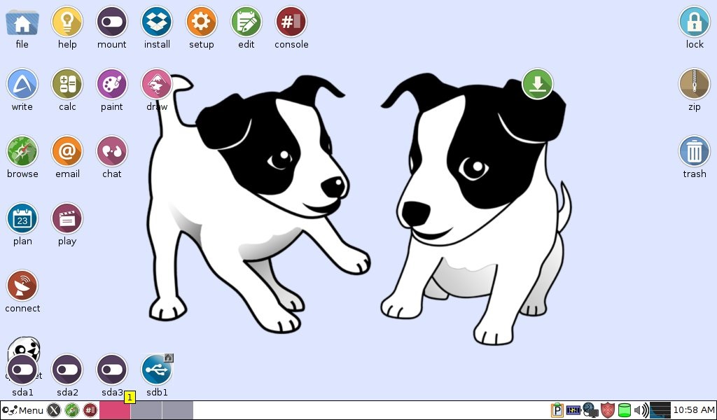
First, install a blank USB memory stick of at least 4MB into the computer that is running Puppy Linux. This drive will appear as an added device in the bottom left of the Linux screen. Take note of the name assigned to this drive (it will be something like sdb1 or sdc1).

From a console window, enter:

cd /

mksquashfs etc root usr /mnt/<drive name from above>/mybackup.sfs 

Wait for the SFS file creation to complete.

Now remove the added thumb drive and then hold down the PC start button until the PC shuts off.

Restoring the backed up configuration

These steps need to be performed from a PC running Windows OS.

Using the same USB memory stick we have been using to prepare this setup, first copy the save file (see red text above) to the root directory.

Then copy the “mybackup.sfs” file created above to the USB memory stick root directory.

Now lets boot from the USB memory stick, which should start in the Puppy Linux OS again.

NOTE: Make sure the PC you are using for this step has at least 4 GB of ram installed. I tried it with a 1GB netbook which failed the process after running out of RAM.

Open two file browser windows (Menu->Filesystem->ROX-Filer).

In one window, navigate to /etc/home/mybackup.sfs. After clicking on the file, select “view”. A folder with the 3 backed up directories (etc root usr) will appear.

In the other file manager windows, navigate to the top-level folder. Among the other directories, this window will also include etc, root, and usr. Copy the files from the first window to the second window.

This can be done by pressing Ctl-A in a blank space in the first window (Selects the 3 folders) and dragging these selected folders to the second window.

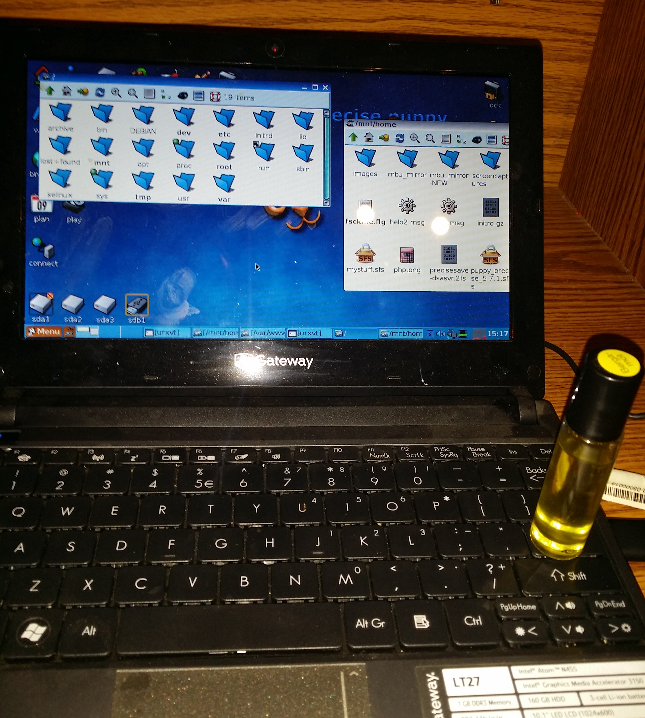
I found that a prompt to confirm the over-write of each file was required and could not figure out how to suppress it. Since there are thousands of files to copy, this requires many mouse clicks or pressing the enter key. As a work-around to automate this step, I used an object that was heavy enough to hold the enter key down. A bottle of essential oil worked well for my enter key.

Use your imagination here!

20160321_151721

And here is where patience is needed. This copy process took over an hour to complete.

Remember, a save file (*.sfs) is provided with this post which already includes these steps, so you don’t have to repeat this lengthy but necessary step.

Once the copy is completed, restart the Linux computer. This should created a clean save file.

Alas, we are ready to resume the mySQL installation!

Console Entries

A few steps are now needed to complete the installation of mySQL. Open a console window and enter the following:

# mkdir /var/lib/mysql

# adduser mysql

# chown -R mysql:mysql /var/lib/mysql

# chgrp -R mysql /var/lib/mysql

#mysql_install_db

# mkdir /var/run/mysqld

# chown mysql:mysql /var/run/mysqld

That’s it. The installation of mySQL Server is complete.

mySQL Server commands

Here are a few console commands to run the server:

Start Server:

# mysqld

Stop Server (Do this from a second console window):

# mysqladmin -u root -p shutdown

Change rood password:

# mysqldadmin -u root password ‘new-password’

or

# /usr/bin/mysqldadmin -u root password ‘new-password’

Here is a reference of other commonly used mySQL server commands.

Quick and Easy Setup

And as promised, I am providing a system image of the full USB LAMP installation in this section, so you can skip most of the steps outlined above and in the first two posts of this series.

Just follow these simple steps, eliminating most of the time-consuming setup:

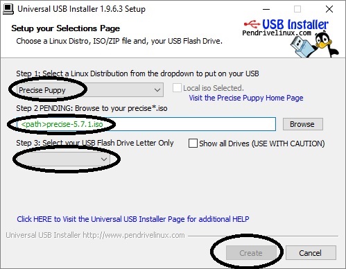
Step 1: Create a Linux USB Memory stick installation per the first part of this post. You can stop prior to installing Apache Server. That package is included with the *.2fs file referenced below.

Step 2: Shut-down the Linux OS running from the USB stick. This will create a save file.

Step 3: Boot a PC to Windows. Install the USB memory stick and delete the save (*.2fs) file from the root directory. Then copy the *.2fs file from this location to the root directory.

NOTE: The file is contained in a ZIP compressed file. The compressed file is over 280MB in size and 1GB uncompressed. Expect the download to require some time (17 minutes with my connection).

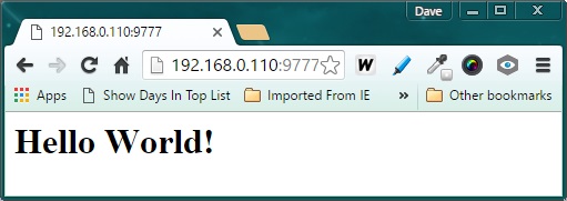
Step 4: Boot a PC with the USB Stick installed to Puppy Linux. This stick now has a complete LAMP stack. But you may need to adjust the IP and port of the server to your specific system. The defaults are IP=192.168.0.110 and port=9777.

Step 5: Set the IP for your system

Step 6: Set the listen port for your system

Step 7: Reboot one more time to create your own save file.

Be sure and review the 3 posts in this series as a guide to using this LAMP stack. A sample HTML and PHP file is provided in the root folder for web pages, /var/www

In Conclusion

In these 3 articles, we have created a USB memory stick Linux environment and added an Apache Web Server, php and mySQL client libraries, and now the popular mySQL Server. Next, we will add phpmyAdmin as a basic tool for administering the mySQL database.

As always, I hope you find this information useful…


Loading

Share This:
FacebooktwitterredditpinterestlinkedintumblrFacebooktwitterredditpinterestlinkedintumblr

Triple Server Update – Part 3: More Server Features

server_update_part3

More Server Features

Ever heard the saying “some’s good, but more is better” ? That idiom certainly rings true when it comes to the capabilities of the multi-purpose server I began developing recently.

The Triple Server introduced with this series initially supported http, mqtt and coap. Subsequently, coap was dropped and replaced with the addition of an Arduino interface. Web configuration was also introduced.

But even then, the system lacked a few highly desirable features. This update builds upon the basic  structure developed so far. Here are the new capabilities introduced with this update:

  • Configurable FOTA port and password
  • Configurable MQTT connection port and client id
  • URL decoding for configurable parameters with special characters
  • FOTA – sketch embedded wireless firmware update support
  • MQTT topics linked to ChipID(MAC)
  • Support for MQTT connection password enabled
  • Unsolicited Arduino MQTT Publications
  • Current GMT added to http header

There features are individually portable. When needed, they can be a great addition to many different IoT projects.

And in case you have not seen the prior posts in this series, here is the story from the beginning:

ESP8266 Triple Protocol Server

Triple Server Update – Part 1: Serving Arduino

Triple Server Update – Part 2: Web Configuration

Triple Server Update – Part 3: More Server Features

Let’s get to the details of the implementation…

Web Configuration

Starting with the Web Configuration panel:

WebConfig
FOTA password and network port settings are added to the configuration page options. When a FOTA password is specified, the user will be prompted to enter it prior to proceeding with a firmware update.

A setting for the MQTT client id has also been included with this update. The past versions of this project simply set the client id to the MQTT username. Finally, a check-box has been added to enable MQTT password connections.

However, the remaining MQTT connection options specified in MQTT Version 3.1.1 such as a last will message have not been implemented in this project. There additional options were not considered essential for this application.

URL decoding

The parameters updated on the Web Configuration page are passed from the html web code back the ESP8266 sketch code using an http “GET” request. Each parameter is added to the URL, a method that can easily be parsed by the ESP8266 c-code using the functions imported from the EspressIf SDK.

This all worked well until special characters were introduced in a password string. In these cases, the special characters are URL encoded, which converts the special characters into something an URL will accept. For example, a space is considered a special character and gets converted to “%20” in an URL.

The problem occurs when the parameter is saved. If “Hello World” is sent as an URL parameters, it becomes “Hello%20World”. This situation is resolved by using an URL decoder prior to saving the value. This restores the parameter to it’s original value, “Hello World” in this example.

Here’s the code used for URL decoding. It should be fairly easy to follow. The basic algorithm looks for a “%hh” code and converts it back to the original “special character” value in the string:


  1. /********************************************************
  2.  *  URL Message Decoder
  3.  ********************************************************/
  4.  
  5. int url_decode(char *encoded_str, char *decoded_str) {
  6.    
  7.     // While we're not at the end of the string (current character not NULL)
  8.     while (*encoded_str) {
  9.         // Check to see if the current character is a %
  10.         if (*encoded_str == '%') {
  11.     
  12.             // Grab the next two characters and move encoded_str forwards
  13.             encoded_str++;
  14.             char high = *encoded_str;
  15.             encoded_str++;
  16.             char low = *encoded_str;
  17.     
  18.             // Convert ASCII 0-9A-F to a value 0-15
  19.             if (high &gt; 0x39) high -= 7;
  20.             high &amp;= 0x0f;
  21.     
  22.             // Same again for the low byte:
  23.             if (low &gt; 0x39) low -= 7;
  24.             low &amp;= 0x0f;
  25.     
  26.             // Combine the two into a single byte and store in decoded_str:
  27.             *decoded_str = (high &lt;&lt; 4) | low;
  28.         } else {
  29.             // All other characters copy verbatim
  30.             *decoded_str = *encoded_str;
  31.         }
  32.     
  33.         // Move both pointers to the next character:
  34.         encoded_str++;
  35.         decoded_str++;
  36.     }
  37.     // Terminate the new string with a NULL character to trim it off
  38.     *decoded_str = 0;
  39. }

FOTA Support

Firmware over-the-air (FOTA) is a very useful option to include with your sketch. The Arduino makes this capability very clean and easy to embed in your code. I found it very useful for debugging code, as it freed up the serial port for test messages. The drawback, however, is that FOTA reduces your effective maximum sketch size in half. This was not a problem in this project, which currently only uses 26% of the available 4MB of my ESP8266-12 flash chip. Just be aware if you are using an older ESP8266-1 with this project, FOTA cannot be used as the sketch uses more than 50% of the 512K flash installed on many of the older ESP8266 versions.

Here is the implementation in this sketch:

A function was added and called in the setup() function.

init_FOTA();


  1. void init_FOTA() {
  2.     String buff;
  3.     int pt;
  4.     //Hostname defaults to esp8266-[ChipID] (no change to default, which is unique (ChipID = last 3 MAC HEX)
  5.     //ArduinoOTA.setHostname("myesp8266");
  6.     
  7.     //Set FOTA Network Port
  8.     GetEepromVal(&amp;buff, EEPROM_MQTT_PT, EEPROM_INT16);
  9.     pt = atoi(buff.c_str());
  10.     ArduinoOTA.setPort(pt);
  11.      
  12.     //Set OTA authentication (password)
  13.     GetEepromVal(&amp;buff, EEPROM_FOTA_PW, EEPROM_CHR);
  14.     ArduinoOTA.setPassword((char *)buff.c_str());
  15.     
  16.     ArduinoOTA.onStart([]() {
  17.         Serial.println("Start");
  18.     });
  19.     ArduinoOTA.onEnd([]() {
  20.         Serial.println("\nEnd");
  21.     });
  22.     ArduinoOTA.onProgress([](unsigned int progress, unsigned int total) {
  23.         Serial.printf("Progress: %u%%\r", (progress / (total / 100)));
  24.     });
  25.     ArduinoOTA.onError([](ota_error_t error) {
  26.         Serial.printf("Error[%u]: ", error);
  27.         if (error == OTA_AUTH_ERROR) Serial.println("Auth Failed");
  28.         else if (error == OTA_BEGIN_ERROR) Serial.println("Begin Failed");
  29.         else if (error == OTA_CONNECT_ERROR) Serial.println("Connect Failed");
  30.         else if (error == OTA_RECEIVE_ERROR) Serial.println("Receive Failed");
  31.         else if (error == OTA_END_ERROR) Serial.println("End Failed");
  32.     });
  33.     ArduinoOTA.begin();
  34.     Serial.print("FOTA Initialized using IP address: ");
  35.     Serial.println(WiFi.localIP());
  36. }

Note that the FOTA port and password values are set from values stored in EEPROM. That means they can be set from the application, so the sketch does not require modification to change the values.

More on that when we go through the updates to the Web Configuration page.

Unique MQTT topics

It a system is built using multiple devices, it may be desirable to ensure that each device sends and receives MQTT message over unique topic names. In order to link the MQTT topic to the ESP8266 device, the default topic now includes an expanded ChipID.

That is to say, while the official ChipID uses the last 3 hex characters of the device’s MAC address, the expanded id in this application uses all six MAC address hex values.

The implementation here simply appends the MAC to a topic prefix. The result is a topic name unique to each ESP8266 device.


  1.  void AddMAC(char * prefix, char * topic) {
  2.      uint8_t MAC_array[6];
  3.      WiFi.macAddress(MAC_array);
  4.      sprintf(topic,"%s", prefix);
  5.      for (int i = 0; i &lt; sizeof(MAC_array); ++i){
  6.           sprintf(topic,"%s%02x",topic, MAC_array[i]);
  7.      }
  8.  }

MQTT Password Connection

The initial design of the MQTT server in this project relied solely on the test.mosquitto.org broker. This simple test site does not offer the option of connecting with passwords. But, of course, a password protected connection is preferred. And recently, I had set up my own MQTT broker, with the capability to require username/password credentials with connections. So adding this to the ESP8266 based server was obviously needed.

Here is the mqtt connection code used to establish password enabled and password-free connections.  Note that the MQTT client class object uses a different client.connect() prototype when using a password to connect.:


  1. void MqttServer_reconnect(void) {
  2.     int fst=10;
  3.     bool connected = false;
  4.     // Loop until we're reconnected (give up after 10 tries)
  5.     while (!client.connected()&amp;&amp;(fst!=0)) {
  6.         Serial.print("Attempting MQTT connection...");
  7.         // Connect to MQTT Server
  8.         if(mqtt_pw_enable) {
  9.             connected = client.connect(mqtt_ci.c_str(),mqtt_un.c_str(),mqtt_pw.c_str()); 
  10.         }
  11.         else {
  12.             connected = client.connect(mqtt_ci.c_str()); 
  13.         }
  14.         if (connected) {
  15.             // Successful connection message &amp; subscribe
  16.             Serial.println("connected");
  17.             client.subscribe((char *)mqtt_rt.c_str());
  18.             fst--;
  19.         } else {
  20.             // Failed to connect message
  21.             Serial.print("failed, rc=");
  22.             Serial.print(client.state());
  23.             Serial.println(" try again in 5 seconds");
  24.             // Wait 5 seconds before retrying
  25.             delay(5000);
  26.         }
  27.     }
  28. }

Unsolicited Arduino MQTT Publications

The Arduino server has been designed to query the Arduino for sensor or pin status. These queries are initiated from external http or MQTT requests. But this structure did not allow the Arduino to independently publish messages to an MQTT topic. That capability has now been added. MQTT messages originating in the Arduino are now possible.

Adding this capability required a simple restructure of the serial part data handler. Now, any time the end of line is received from the serial port, the ESP8266 sends the response to the http or mqtt channels when initiated, and to the mqtt topic when received without an initial request originating from the ESP8266.

This change impacted the function that initiates requests to the Arduino via the serial port. With the revised implementation, the function no longer waits for a reply:


  1. String ArduinoSendReceive(String req) {
  2.     String fromArduino = "";
  3.     Serial.println(req);
  4.     long start = millis();
  5.     fromArduino = "";
  6.     return fromArduino;
  7. }

Instead, a new function, “MonitorSerialLine()”, was added to process all data received on the serial port, both initiated and unsolicited.


  1. void MonitorSerialLine() {
  2.     if(arduino_server) {
  3.         while (Serial.available()) {
  4.             // get the new byte:
  5.             char inChar = (char)Serial.read();
  6.             // add it to the inputString:
  7.             SerialInString += inChar;
  8.             // if the incoming character is a newline, set a flag
  9.             // so the following code can process it
  10.             if (inChar == '\n') {
  11.                 NewSerialLineRx = true;
  12.             }
  13.         }
  14.         //Send Received String as MQTT Message
  15.         if(NewSerialLineRx) {
  16.             //If not server request, just forward Arduino Message to MQTT
  17.             if(active_svr_rqst == SVR_NONE) {
  18.                 active_svr_rqst = SVR_MQTT;  
  19.             }
  20.             Server_SendReply(active_svr_rqst, REPLY_TEXT, SerialInString);
  21.             active_svr_rqst = SVR_NONE;
  22.             SerialInString="";
  23.             NewSerialLineRx=false;
  24.         }
  25.         //Check for timeout for Arduino Server requests
  26.          if(active_svr_rqst != SVR_NONE) {
  27.              if(start_wait==0) start_wait = millis();
  28.              if( (millis() - start_wait)  &gt;5000 ) { //5 sec timeout
  29.                   SerialInString = "no arduino reply received";
  30.                   Server_SendReply(active_svr_rqst, REPLY_TEXT, SerialInString);
  31.                   //Reset Request Parameters
  32.                   active_svr_rqst = SVR_NONE;
  33.                   start_wait=0;
  34.                   SerialInString="";
  35.                   NewSerialLineRx=false;
  36.              }
  37.          }
  38.     }
  39. }

Current GMT

gmt

The http response header requires an identification of current GMT (for the Date header) and a current date offeset (for expiration headers). Prior versions of this project simply added hard-coded, static values for these headers. While it did no impact the http response transmission, it was obviously inaccurate header content.

In order to create accurate date headers, current GMT must be known. So time is now retrieved from a NIST server. This required an initialization routine to be run in the sketch’s setup() function. The offset is set to 0 so we get GMT when time is requested.


  1. void init_GmtTime() {
  2.     configTime(0, 0, "pool.ntp.org", "time.nist.gov");
  3.     Serial.print("\nWaiting for time");
  4.     while (!time(nullptr)) {
  5.         Serial.print(".");
  6.         delay(1000);
  7.     }
  8.     Serial.print("\r\nTime has been acquired from internet time service\r\nCurrent GMT: ");
  9.     time_t now = time(nullptr);
  10.     Serial.println(ctime(&amp;now));
  11. }

Here is how time is now retrieved when creating an http header:


  1. String gmt,expire;
  2. time_t now = time(nullptr);
  3. gmt = ctime(&amp;now);
  4. now += 3600 * 24;  //Expires in 1 day
  5. expire = ctime(&amp;now);
  6. gmt = gmt.substring(0,3) + "," + gmt.substring(7,10) + gmt.substring(3,7) + gmt.substring(19,24) + 
  7. gmt.substring(10,19) + " GMT";
  8. expire = expire.substring(0,3) + "," + expire.substring(7,10) + expire.substring(3,7) + 
  9. expire.substring(19,24) + expire.substring(10,19) + " GMT";

The string returned from a call to ctime() is in a different format than what is needed in the http. The String class “substring” method is uses to re-sort the ctime() string into the needed http header format.

ctime() format:

Mon Mar 14 08:23:14 2016

http header format:

Mon,13 Mar 2016 08:23:14 GMT

In Closing

This update establishes a solid framework for building IoT projects with both http and MQTT server support. While Arduino is used in the example, any external device with a standard serial link can also be easily added to this structure. And when the system is deployed, updates can be deployed wirelessly, eliminating the need to connect a physical serial interface to the system.

Here is the updated GitHub repository for this project.

I hope you find this information useful…

Loading

Share This:
FacebooktwitterredditpinterestlinkedintumblrFacebooktwitterredditpinterestlinkedintumblr

USB LAMP Web Server

servericon

Your Personal http Server

If you would  like to have your own personal web server, running industry standard software, all from a boot-able USB stick, read on…

One of the most useful tools for home automation and web development is a host server. And the most widely used server is of course, Apache.

This article marks the start of a 5-post series that provides step-by-step instructions for setting up your own USB memory stick based http server. We’ll start with the basic LAMP stack in the first three articles, and then add-on some extras to extend the functionality.

What’s LAMP?

LAMP covers the essential ingredients of a web server:

  1. Linux – The operating system
  2. Apache – http server
  3. mySQL – database
  4. PHP – server-side scripting language

Here are the topics planned for this series:

Update: Bonus Topics

Part 1 – Setting up the Linux Apache Server

When finished with part one, you will have the LA (Linux and Apache) LAMP components up and running.

Let’s get to it…

Prerequisites

  • Blank USB Memory stick (4GB minimum)
  • PC with USB port that can be dedicated for the server

While I cannot claim to be a Linux expert, I do have some experience working with the single user Puppy Linux distribution. Being a familiar setting, that is what was selected for this exercise.

But hold on, before you start there is one more selection to make….

You see, there are several versions of Puppy Linux to pick from. My first attempt at this used the most current version, called Slacko Puppy 6.3. However….sparing you the details, I ran into some insurmountable obstacles to completing a successful installation of Apache server with Slacko Puppy.

So I moved on to a Puppy Linux version that works with the Apache Server.

The version that worked is called Precise Puppy 5.7.1

Installing the Linux Operating System

As with many Linux distributions, the installation is really quite simple. Just download the ISO image and a USB installer. That’s it. Here is where you can get both:

Now for the installation. Just install your USB stick and start the installer program. The start up screen will provide 3 easy-to-follow instruction steps.

  1. Select the distribution (Select “Precise Puppy”)
  2. Select the iso file (from the folder that has the downloaded ISO image)
  3. Select the USB stick drive letter.

UUSBinstaller

Then click on the “Create” button to start the installation.

Once the installer is finished, you can boot any PC to the newly installed Puppy Linux simply by putting this memory stick in the PC’s USB port and rebooting (Boot to USB first must be selected in the bios first, of course).

After the computer has booted to Linux and you have completed the self-guided first boot process, you need to perform one additional step before installing Apache.

NOTE: It is recommended that a wired internet connection be used for this and all processes during installation.

First, you need to update the package database. This is a very simply process. Just launch the Puppy Package Manager (Menu->Setup->Puppy Package Manager) and click on the “Configure package manager”. A window will appear with an “Update now” button.

updatenow

Click that button and press enter each time the yellow window prompts you. There will quite a few “Enter”s required to complete this step.

Once complete, exit the Puppy Package Manager. If this is still your first Linux session using the memory stick, it is also recommended that you restart the computer (from the bottom MENU option). The restart will create a save file that will be updated every time you exit Linux. This file contains all the changes you have made to the originally installed Linux distribution.

Adding Apache Server

Now let’s get Apache.

Launch the Puppy Package Manager again. In the search window (Find), enter “apache2”.

findapache

Select “apache2_2.2.22” from the listed results.

selectapache

A pop-up windows will appear as shown below:

examinedepenancies

Click the “Examine dependencies” button.

Click “Download-and-install selected packages” in the window below.

downloadinstall

Another window will appear. Click “Download packages” in this window.

downloadnow

Manual Apache Server Installation Steps

Once the download is complete, we are ready to make the necessary adjustments in order for the server to properly start. We will be adding a new user and add links to the files and directories the Apache server is expecting.

Open a terminal by clicking on the desktop icon “console”.

In the console window, enter the following lines. End each line with the <Enter> key. The entries are shown in red text:

# adduser www-data
adduser: /home/wwwdata: No such file or directory
Changing password for wwwdata
New password:
Retype password:
Password for wwwdata changed by root

Note that <enter> is pressed with no entry for the password.

Now lets continue with the next lines:

# touch /etc/apache2/httpd.conf

# ln -s /etc/apache2/mods-available/auth* /etc/apache2/mods-enabled/

# ln -s /etc/apache2/sites-available/default /etc/apache2/sites-enabled/

# ln -s /etc/apache2/mods-available/alias* /etc/apache2/mods-enabled/

# ln -s /etc/apache2/mods-available/ldap* /etc/apache2/mods-enabled/

# chown www-data:www-data /var/www

# touch index.html

# chown www-data:www-data /var/www/index.html

# ln -s /etc/apache2/mods-available/dir.* /etc/apache2/mods-enabled/

Server Test Page

Lets put the typical “hello world” message in our index.html file so we know it is served properly.

The file is in the /var/www directory, which is the apache server root folder. Open that file and fill it with the following text:


  1. &lt;html&gt;
  2.     &lt;body&gt;
  3.         &lt;h1&gt;Hello World!&lt;/h1&gt;
  4.     &lt;/body&gt;
  5. &lt;/html&gt;

Now there are only two more things needed to complete the server installation:

1. Set the IP
2. Set the Listening Port

Setting the IP

From the terminal, enter (a wired network cable should be installed):

# /sbin/ifconfig eth0

The computer will respond with several lines. The second line should contain the ip. My second line began with:

inet addr:192.168.0.110

This IP value needs to be added to the hosts file. It is at /etc/hosts.

The first line should be:

127.0.0.0 localhost <your computer id>

Change it to (using your IP value):

192.168.0.110 localhost <your computer id>

You can now save and close the hosts file.

Setting the Listen Port

Now lets finish this off by setting the server listening port. If you want to leave the server listening on the default port (80), you can skip this step.

Open the file: /etc/apache2/ports/ports.conf

Near the top of the file, you will see the following 2 lines:

NameVirtualHost  *:80

Listen 80

Change “80” in these lines to whatever port you want the server to listen on.

Save and close this file.

Now open the file: /etc/apache2/sites-enabled/default

The top line should be:

<VirtualHost *:80>

Change “80” in this line to the same port number in the first file.

Save and close this file.

Testing the Apache Server

First, start the server by entering the following in a console window:

/etc/init.d/apache2 restart

The console should respond with:

startapache

Now, using a web browser from a different computer on your network, enter (replacing 80 with the port number configured in the previous step):

192.168.0.110:80

The browser response should be (my listen port was 9777):

HelloWorld

Congratulations! Your Apache Server is now functional.

This is an enormous first step. You can now serve html files from this server, both within your local network and globally from anywhere on the planet!

In Closing

This is not the end, it is only the beginning of your own host server. I will share my setup as the components are added. Part 2, adding PHP to the server will be coming soon.

I hope you find this information useful…

Loading

Share This:
FacebooktwitterredditpinterestlinkedintumblrFacebooktwitterredditpinterestlinkedintumblr

Your Own MQTT Broker

mqtt

Like many folks, I too started out using the public MQTT broker at test.mosquitto.org. It’s a great way to get started – simple, easy to get working, and FREE! But it does not take long to realize it is unsecured. Anyone can listen in on your topics and there are no logon credentials required or offered as an option.

So I got to searching for a better broker…

One with security. And all the options available with the MQTT standard. Things like:

  • Security Authentication (passwords,certificates)
  • Simultaneous websockets and mqtt (tcp) listeners
  • Persistent Messages

But I did not want to pay for the service. The obvious solution was to host your own broker, either on a host server, or on your local network with broadband access via a router.

Since my host server does not permit continuously running scripts or programs, was limited to a local network solution. But with a broadband connection, it would be on-line and accessible anywhere.

After some research, the most promising options included:

  • PC Broker with Windows OS
  • PC Broker with Linux OS
  • Flash Driver Linux Distro Broker
  • Raspberry Pi2 Broker
  • Android Device Broker
  • Embedded micro-controller

I have read numerous comments about poor (slow) performance using a Raspberry Pi, and since I do not own one, that option was ruled out. For the same reason, I thought about hosting a broker on the trusty ESP8266 but decided against it, at least for now.

And while it would be great to use an old Android phone as an MTTQ broker, the path to get there was a bit murkier than using a Linux hosted server.  It can be done, but few have gone this path. That is, there is little in the way of guidance so this would require significant development.

Windows? Maybe with Windows Server OS running. But that’s not what I got. No.

So looking around at my inventory, I decided to use an unused Window 7 netbook. But, rather than overwriting the hard-drive, a USB flash drive installation was done.

Linux running an MQTT broker when booting to the flash drive.

Windows 7 with the flash drive removed.

While there were a few challenges along the way, it turned out to be a great solution. It has been running continuously now for over a week – flawlessly.

Here is how to set it up…

Linux Installation

Looking for a small, clean Linux distribution, I selected Puppy Linux.  The choice was easy to make, since it had already been setup and running. This post provides step-by-step instructions to configure your flash drive. Follow all the instructions as you will need the development environment to build the MQTT application.

Building the MQTT Broker Application

First thing needed is a copy of the Mosquitto 1.4.7 broker. You can get it here. Then, with the flash drive in a Windows PC, copy the unzipped contents of the folder org.eclipse.mosquitto-1.4.7 to the flash drive in a new folder in the path:

<flash drive>/MyPrograms/mosquitto

You can now install the flash drive in your target computer and reboot. It should start in Puppy Linux.

puppy-start

Before we can build the application, a couple of steps are needed.

  • Install Mosquitto Package
  • Install libwebsockets
  • Edit build configuration file

Let’s go…

Installing the Mosquitto Package

  1. From the Desktop, click on the blue “install” icon.
  2. Click on the “Install Applications” tab.
  3. Click on the Puppy Package Manager icon.
  4. Enter “mqtt” into the search box and hit the “Enter” key.
  5. Click on the mosquitto_0.15 Package.
  6. Click “Install” (Upper right of windows).

Installing the libwebsockets Library

  1. From the Desktop, click on the blue “install” icon.
  2. Click on the “Install Applications” tab.
  3. Click on the Puppy Package Manager icon.
  4. Enter “libwebsockets” into the search box and hit the “Enter” key.
  5. Click on the libwebsockets3_1.2.2.1 Package.
  6. Click on the libwebsockets-dev_1.2.2.1 Package.
  7. Click “Install” (Upper right of windows).

Edit build configuration file

  1. From the Desktop, click on the green “edit” icon.
  2. Click Open, then under “Places”, click “File System”.
  3. Under “Name”, click “mnt”. Then click open.
  4. Under “Name”, click “home”. Then click open.
  5. Under “Name”, click “MyPrograms”. Then click open.
  6. Under “Name”, click “mosquitto”. Then click open.
  7. Under “Name”, click “config.mk”. Then click open.
  8. Scroll down to “WITH_WEBSOCKETS:=no and change to “yes”
  9. Save the file and exit.

Building the broker application

We are now ready to build the application. This is really simple. First, open the console window by clicking on the “console” icon from the desktop. Now switch to the directory that contains the mosquitto source code by entering:

cd /mnt/home/myprograms/mosquitto/src

now build the application by entering:

make

Configuring the MQTT Broker Application

Edit mosquitto run-time configuration file

  1. From the Desktop, click on the green “edit” icon.
  2. Click Open, then under “Places”, click “File System”.
  3. Under “Name”, click “mnt”. Then click open.
  4. Under “Name”, click “home”. Then click open.
  5. Under “Name”, click “MyPrograms”. Then click open.
  6. Under “Name”, click “mosquitto”. Then click open.
  7. Under “Name”, click “mosquitto.conf”. Then click open.
  8. From the edit menu, select”Save as” and save this file to the src folder. The full file path should now be /mnt/home/myprograms/mosquitto/src/mosquitto.conf.
  9. Scroll down or search for “#allow_anonymous true”. Change this to “allow_anonymous false”. Remember to delete the # so this is not commented out. This will force the broker to require usernames and passwords to connect.
  10. Scroll down or search for “#user mosquitto”. Change this to “user nobody”. Remember to delete the # so this is not commented out.Puppy linux does not have a user named “mosquitto” but it does have one named “nobody”. Since Puppy Linux is a single user distribution, it does not allow you to add users.
  11. Scroll down or search for “#password_file”. Change this to “password_file pw.txt”. Remember to delete the # so this is not commented out.
  12. Scroll down or search for the text “#protocol mqtt”. Just after this line, add the following 4 new lines:
    1. listener 11883
    2. protocol mqtt
    3. listener 18080
    4. protocol websockets
  13. Save and exit the file

What step 9 does is configure the broker with two listeners, one with standard mqtt (tcp) protocol and one with websockets.

While any port can be used, a one was added to the standard port numbers so our broker is not in conflict with the “well-known” mqtt ports. This could be important in the complicated event that your client is connected to two different brokers at the same time. In this case, the ports can only be open once. This eliminates potential conflicts.

Creating a password file

Using the file editor (edit icon from the desktop), save a blank file in the src folder:

/mnt/home/myprograms/mosquitto/src/pw.txt

Add a few username/password entries in this file in the format, for example:

username:password
user2:password2

Save the file. Also make a copy of this file for off-line storage.

Now run the password utility. This will change the plain text passwords in the file pw.txt to a hashed value. Run the password utility from the console:

cd /mnt/home/myprograms/mosquitto/src
./mosquitto_passwd -U pw.txt

If you open pw.txt, you will find the plain text passwords have been replaced with a hashed value.

Opening the Linux Firewall

network-firewall-icon

Are we ready to run the broker yet? Almost. But there is one more thing needed in order to access the broker from another device. We need to configure Linux to allow external connections.

Open the file /etc/hosts.allow

It should contain one line:

ALL:LOCAL

Change this to:

ALL:ALL

Save and exit the file.

If you want a more restrictive environment, it is suggested that you research configuration settings for the Linux hosts.allow file. For the purpose of this example, we are opening the MQTT Broker to anyone with proper username/password credentials.

Starting the Broker

Now to start the broker, just go to the src folder and enter the following:

cd /mnt/home/myprograms/mosquitto/src
./mosquitto -c mosquitto.conf

The startup console should display:

start_mosq

The warning occurs because ipv6 is not supported. But this is of no concern for the typical ipv4 addresses. While the application was initially build in the ../src directory, it can be moved and executed from any location of your choosing. just remember to also include the password file utility, the config file and the password file. These are the files needed to run the application:

mosquitto
mosquitto_passwd
mosquitto.conf
pw.txt

Testing the Broker

You probably have your own devices to connect to and test the broker. With the configuration of this broker, you will need to include a username and password when connecting. I like to use the Google Chrome MQTTlens extension and the Android MyMQTT App when making quick MQTT connection checks. I’ve provided additional details for using these MQTT tools in this post.

Port Forwarding and DDNS 

icon-port-forwarding

While you can access this MQTT  broker from any device on your LAN subnet, world-wide broadband access will require configuring your router to forward MQTT port requests to the device running the broker. This is called port forwarding. Please refer to this post for more information about configuring port forwarding and DDNS.

In Closing

This broker setup provides you with all the features of the MQTT specification. One of the best features is the ability to operate a mixed protocol system. This provides an connection to devices using either mqtt (tcp) and websocket protocol together. And you can enable any level of security needed, from simple passwords to security certificates. And since it is running locally, you are in full control.

Next up. I am planning to update my MQTT App inventor template application to support the basic security credential provided by this broker.

I hope you find this information useful…


Loading

Share This:
FacebooktwitterredditpinterestlinkedintumblrFacebooktwitterredditpinterestlinkedintumblr

MQTT for App Inventor – Adding Configurable Settings

App Inventor to MQTT Communication

In my last post, a basic MQTT client portal for App Inventor was introduced. As result, there has been some interest expressed for TCP socket support. Note that the implementation presented relies on WebSockets. Due to security vulnerabilities, pure TCP sockets are simply not possible with this design. If TCP sockets are needed for MQTT communication at your IoT device, a broker capable of both WebSockets and TCP sockets should be used – Websockets on the App Inventor side, and TCP sockets on the IoT device end.

Adding Configurable Setting

My next step was to refine the App Inventor project to support configurable MQTT setting.

NOTE: If you just want to review and use the updated App Inventor project without the walk-through that follows, simply use the files provided in this Github repository.

The first challenge while adding this capability was the inability to grant file system access to the JavaScript code. Native Android Apps can overcome this with a change to the App’s manifest file. But App Inventor does not expose this application setting.

So the App Inventor file component had to be used to read and write to the file system. The configuration file settings are then passed on to the JavaScript to update the MQTT connection parameters.

mqtt_cfg

App File Location

This App now uses two files stored on the Android device. These files have been moved to a common location which should be the same on most Android devices:

File Description
/sdcard/mqtt/mqtt_appinventor.html The JavaScript MQTT App Inventor Server
/sdcard/mqtt/cfg.txt MQTT Configuration

Configuration file

For this example, 3 parameters are configurable:

  1. Broker: This can be any on-line broker, on your own network or either publicly or privately provided.
  2. Request Topic: MQTT topic used to send a client request
  3. Reply Topic: MQTT topic used to reply results to the client.

Since this example uses the publicly available broker ‘test.mosquitto.org’, username/password authentication is not provided. You could easily be add this to the example provided here, however, if you are using a broker requiring authentication.

The file is formatted as a JSON string. This makes it very easy for the JavaScript to parse the values. The first time the App is run, these configurable parameters are set to the values shown in this JSON string:

{
“mqtt_broker”:”ws://test.mosquitto.org:8080/mqtt”,
“mqtt_txtopic”:”MyMqttSvrRqst”,
“mqtt_rxtopic”:”MyMqttSvrRply”
}

App Inventor File Read/Write

When the screen used to edit the configurable parameters is open, it first reads the cfg.txt file, extracts the parameter setting, and uses those values to populate the screen fields.

But when using App Inventor, there are no (at least none that I am aware) libraries available for parsing JSON. So I created the procedure “GetParam”, which extracts the cfg.txt values with 3 calls, one for each parameter.

readfile

Two values are determined initially in order to extract the value. First is the position in the string that the value starts. The other value is the string length. These values are determined by using App Inventor’s string search (starts at) feature to find something unique (StartPiece and LenPiece) around the value wanted, and an offset from the parameter value’s exact position in the string.

getparam

Once extracted, the “Edit Configuration” screen is populated with the values from this file.

cfg_gui

Saving the values is just the opposite. The values from the screen are formatted into a JSON string and then saved back to the same file, cfg.txt.

save

When this screen is exited, the new configuration values are sent to the JavaScript code. The JavaScript uses these new values and closes, then opens the MQTT connection with the new values. Here is how that has been implemented…

Updated Main Screen

As I have gained knowledge coding with the App Inventor, it became obvious that meaningful names were needed for project components. Much to my surprise, this does not extend to the main screen. It is called “Screen1” by default, and cannot be changed.

The screen GUI was changed somewhat for this update. Two new buttons were added. One to open the configuration screen and one to exit the application. The components were also move to the bottom of the screen (don’t want to cover the mosquito, do we?).

main

Every time the main screen is open, it’s 100 ms timer restarts. That is where the command is sent to the JavaScript to update the configuration settings.

Once.

It is sent 1/2 second (500 ms) after the screen is open. An important note: I found that the command did not execute if initiated concurrently with the opening of the screen. So the 500 ms delay (5 timer iterations) was introduced using a timer, which works every time.

timer

At 500 ms, the cfg.txt file is read. “CFG:” is inserted at the beginning of the string before being sent to JavaScript via the WebViewString.

sendcfg

A handler is also included for the first time this application is run. In that case, the cfg.txt file does not exists. As result, an exception is thrown when attempting to “ReadFrom” the file. An error handler was added for this condition.

error2

Error 2101 occurs when the file does not exist. In this case, a file is created with default values for the configurable parameters.

JavaScript for Configurable MQTT

The JavaScript also required revisions to support MQTT configurable parameters. The original version only handled IoT requests. These were identified with ‘GET:’ as the first 4 characters. Similarly, the added configuration command is now recognized as WebViewStrings beginning with “CFG:”


  1. // 10 Hz WebViewString polling timer function --------------------------------------&gt;
  2. function AppInventorServer() {
  3. var request = window.AppInventor.getWebViewString(); // Get WebViewString
  4.     if(request.substring(0, 4)=="GET:") {                // Validate request
  5.      window.AppInventor.setWebViewString("");         // Reset String (process once)
  6.         $("#request").val(request.substring(4, request.length)); //set request html textbox
  7.         SendMqttRequest();                               // Send Mqtt Request
  8.     }
  9.     if(request.substring(0, 4)=="CFG:") {                // Validate request
  10.      window.AppInventor.setWebViewString("");         // Reset String (process once)
  11.         var cfgpar = JSON.parse(request.substring(4, request.length));
  12.         txtopic = cfgpar.mqtt_txtopic;
  13.         rxtopic = cfgpar.mqtt_rxtopic;
  14.         mqtturl = cfgpar.mqtt_broker;
  15.         client.disconnect();
  16.     }
  17.     setTimeout(AppInventorServer, 100);   // run AppInventorServer() in 100 ms
  18. }

As you can see, parsing and extracting values from a JSON string is very simple and straight-forward with JavaScript. Once the new values are set, the MQTT broker connection is updated with a call to ‘client.disconnect()’.


  1. // Callback executed upon MQTT broker disconnection --------------------------------&gt;
  2. client.ondisconnect = function(rc){
  3. client.connect(mqtturl);
  4. };
  5. // Callback executed upon MQTT broker connection -----------------------------------&gt;
  6. client.onconnect = function(rc){
  7. client.subscribe(rxtopic, 0);
  8. };

Improving the Arduino Digital Commands

The original project used hard-coded values for the Digital Get and Set commands. Ok for an example, but not so good if you need access to a channel outside the card-coded value. That was rectified with this update, which now supports digital channel selection.

dig_new2

Select “Set Arduino Digital Channel” and a new screen is open. This screen allows you to select the channel to set.

digital_sel

This screen is open with a “start value” received from the main screen that called it.

select_digit

The value returned when OK is clicked depends on the startValue. If it is a “Set” command, an Arduino SetDigital request string is returned. The selected channel and logic state from the screen’s selections are also returned with the request.

Notice that a call to close the screen is made before the main screen (Screen1) is re-opened. That is necessary when returning a startValue. If the screen is not closed, it remains open for the duration of the App execution.

Another call to this window will open another instance of the window. This is effectively a memory leak which will crash you Android device eventually. Takeaway: Close the screen before opening a new screen when passing a start value to avoid memory leaks.

As you can see, a similar value is returned for “Get” requests. But when “Get” requests are received, the channel state is not selected, it is returned from the request. When this screen is open with a “Get” request, the channel state selection GUI is suppressed.

get_digit

Sending the Arduino Digital Request

When the Digital channel selection screen is closed, the main screen is reopened. But how does it know to send the Arduino command to MQTT? After all, the screen is opened fresh, just like when the app is started.

Not quite. Remember the ‘startValue’ returned from the digital selection? That is checked to determine whether an arduino request is needed. It is done in the 100ms timer callback.

timer

At 500 ms after the screen is open, the MQTT configuration is sent to the JavaScript. But then, at 1000 ms (10 100 ms intervals), the startval string is check for a non-null value. If a string is present, it is sent to the JavaScript via the WebViewString, by calling the SendRequest procedure.

send_request

Exiting the Application

Just one more thing and we are done with this update. I thought it would be nice to add an ‘Exit’ button to close the app. What I found was that it required several clicks before the app would actually close. What was happening was that every time a different screen returned to the main screen, the previous main screen remained open and a new main screen instance was created.

Not exactly what I had in mind. Another memory leak!

This was corrected by adding a ‘close screen’ before each time one of the two added screens was open. This guarantees only one screen is open at a time while the app is running.

cfg_mqttt

With this correction, the Exit button works as intended, with only one click required.

In Closing

This example should provide a framework for anyone needing to use MQTT with an App Inventor project. The main caveat is that a broker that supports WebSockets is required. I leave it up to you as an exercise to add username and password credentials to the mqtt connection settings. The basic structure is here. And it should also be a simple task to add “GetAnalog” to the Arduino request options. Go ahead, you can do it! If you need it.

Again, here are the project files.

I hope you find this information useful…

Loading

Share This:
FacebooktwitterredditpinterestlinkedintumblrFacebooktwitterredditpinterestlinkedintumblr

MQTT For App Inventor

appinventormqtt

App Inventor is a visual, easy-to-use online Android Application development platform. It is a great vehicle that empowers the do-it-yourself enthusiast to develop mobile IoT clients without battling the steep learning curve of traditional text-based development platforms.

Aside from the basic programming language constructs, all you need is a method of accessing your Internet enabled devices. And many developers prefer to use MQTT, a machine-to-machine connectivity protocol, to communicate externally with their IoT “things”.

But up to now, there has not been a lot of information available showing how to use MQTT with App Inventor. Here is what I have come up. It’s a working example of an Android App Inventor project using MQTT.

The Concept

When I first looking into this, it seemed that those looked into this were trying to adapt the existing App Inventor Web components to work with MQTT. But that just won’t work. MQTT requires a TCP connection to remain open for the entire time the App is running. And App Inventor only provides an http interface.

App Inventor also did not appear to provide a method of adding a c-based MQTT library. Another possibility was to interface with JavaScript. After all, I had already been successful in implementing an MQTT webpage using JavaScript.

But how can you interface with JavaScript using App Inventor?

After investigating App Inventor features deeper, the answer popped into my head like a light bulb flipping on. The solution was right there…

WebViewString .

That’s it! You can set the WebViewString from App Inventor. And JavaScript can read and act upon the contents of the WebViewString  object. All I had to do was setup a basic communication scheme with this and MQTT communication would be possible.

Overall Communication Structure

Here is how it works…

App inventor sets the WebViewString to the MQTT topic payload that it wants to publish. Then, a JavaScript file monitoring the value of the WebViewString for MQTT requests picks up the payload and publishes it. The IoT device that subscribes to the topic then detects the request, acts on it, and returns a reply via an MQTT topic publication.

The rest of the sequence should be obvious. The JavaScript subscribing to the MQTT topic published by the IoT device then forwards the reply back to App Creator by changing the value of the WebViewString .

blockdiagram

That’s it. And here is the implementation…

App Inventor GUI

For this example, the App Inventor GUI has intentionally been kept simple. Just one user action provided: Click on the button to select an MQTT request and wait for the reply string to appear.

gui4

Since this example uses the Triple Server Update ESP8266 sketch from my previous post, these are the options that can be selected when the button is clicked. They can be easily customized for your own system requirements.

options3

These selections are currently just the raw strings sent to the IoT based MQTT server. The App Inventor code could be refined, if desired, to make it more user friendly. Such as using a channel selector input as well as a logic state selector (HI or LO). But for this example, raw strings are suffice.

App Inventor Initialization Code

Here is the App Inventor code used to initialize the MQTT request options. This code executes when the App’s one and only screen opens. Just change the text in the list for your own MQTT topic payloads.

code_Initialize

Note that the JavaScript MQTT server file pointer is also initialized here. This file, locally stored in the Android SDcard, is open when the App starts. More about that later in this article.

App Inventor Send MQTT Request Code

When one of the request options are selected (picked), the WebViewString is set to this request value. It is prefaced with “GET:” so the JavaScript code knows what is to follow is an MQTT request.

code_Send

App Inventor Receive Reply Code

Finally, the App Inventor continuously monitors the WebViewString for replies from the JavaScript. While I do not prefer to use polling loops, that was the only mechanism I was able to come up with for this. The polling timer is set to repeat every 100 ms, or 10 times per second.

code_MonitorReply

WebViewString is first validated as a reply by confirming it is not blank and does not start with the request “GET:” prefix. If these conditions are met, the GUI reply string is set to the WebViewString value. Note that the WebViewString value is set to “” after read so this polling function does not process it more than once.

JavaScript For MQTT

Since I already had a working MQTT webpage from a prior project, it was simply reused for this example. Of course, the irrelevant parts were remove and the WebViewString object was added. While it can be saved anywhere, for this project, the file is stored on the Android device’s SD card. File installation instructions are provided in the GitHub repository for this project.

JavaScript Initialization Code

The initialization code first brings in the required MQTT and jquery libraries from online sources:


  1. &lt;!-- mosquitto MQTT ----------------------------------------------------------------&gt;
  2.  &lt;script type="text/javascript" src="http://test.mosquitto.org/mosquitto.js"&gt;&lt;/script&gt;
  3.  &lt;!-- jQuery ------------------------------------------------------------------------&gt;
  4. &lt;script src="https://ajax.googleapis.com/ajax/libs/jquery/1.11.2/jquery.min.js"&gt;&lt;/script&gt;

Next,  default values are set for the request, MQTT broker, and the request/reply topics. An instance of a Mosquitto client is also created,


  1. // Set Default Request -------------------------------------------------------------&gt;
  2.  $("#request").val("/?request=GetSensors");
  3.  // Set Default MQTT Url ------------------------------------------------------------&gt;
  4.  var mqtturl = "ws://test.mosquitto.org:8080/mqtt";
  5.  var txtopic = "MyMqttSvrRqst";
  6.  var rxtopic = "MyMqttSvrRply";
  7.  // Create MQTT client instance -----------------------------------------------------&gt;
  8.  client = new Mosquitto();
  9.  client.run = 0;

Finishing the initialization, the MQTT broker connection is established and the WebViewString polling loop is started.


  1. //executes once after window is loaded ---------------------------------------------&gt;
  2.  function windowloaded() {
  3.      client.connect(mqtturl);   // Connect to MQTT broker
  4.      AppInventorServer();       // Start polling WebViewString
  5.  }
  6.  window.onload = windowloaded;  // Launch windowloaded()

JavaScript Receive Request Code

Here is the polling loop, which checks for new MQTT requests from App Inventor.


  1. // 10 Hz WebViewString polling timer function --------------------------------------&gt;
  2.  function AppInventorServer() {
  3.   var request = window.AppInventor.getWebViewString(); // Get WebViewString
  4.      if(request.substring(0, 4)=="GET:") {                // Validate request
  5.       window.AppInventor.setWebViewString("");         // Reset String (process once)
  6.          $("#request").val(request.substring(4, request.length)); //set request html textbox
  7.          SendMqttRequest();                               // Send Mqtt Request
  8.      }
  9.      setTimeout(AppInventorServer, 100);   // run AppInventorServer() in 100 ms
  10.  }
  11. // Publishes MQTT topic contained in html #request object --------------------------&gt;
  12. function SendMqttRequest() {
  13. client.publish(txtopic,$("#request").val(),0,0);
  14. }

If the WebViewString starts with “GET:”, it is considered to be valid. In that case, the WebViewString is first set to “” to avoid processing the request again at the next 100 ms interval. The request string is then stripped from the WebViewString and published as an MQTT topic. This polling loop restarts every 100 ms.

JavaScript Reply Callback Code

Whenever the subscribed MQTT topic message is received, a JavaScript callback function is executed.


  1. // Callback executed upon receipt of MQTT message ----------------------------------&gt;
  2. client.onmessage = function(topic, payload, qos){
  3. if(topic==rxtopic) {
  4.     setpayload(payload);
  5.     }
  6. };
  7. // Sets WebViewString and html payload text box to 'payld' -------------------------&gt;
  8. function setpayload(payld) {
  9. window.AppInventor.setWebViewString(payld); // Set WebViewString
  10.     $("#payloadmqqt").html(payld); // Set html textbox
  11. }

This callback simply passes the reply (MQTT topic payload) back to App Inventor through the WebViewString. An html textbox is also filled with this reply string.

That’s it!

The App Inventor project file and JavaScript html file is available on GitHub here. Instructions for installing the JavaScript file on an Android device is also provided at this same GitHub location.

Hope you find this information useful.

And stay tuned. My next step will be adding non-volatile configuration for the MQTT parameters. This will provide the capability to change MQTT brokers and topics without changing the contents of the installed html file.


Loading

Share This:
FacebooktwitterredditpinterestlinkedintumblrFacebooktwitterredditpinterestlinkedintumblr

Triple Server Update – Part 2: Web Configuration

Have you ever moved your ESP8266 system from one Wifi location to another? Or perhaps made an extra one for your friend? In many cases, the initial setup requires a change to the sketch, to adjust the Wifi parameters to match the new access point—that is—unless the local settings are stored in the ESP8266 EEPROM.

What’s great about the EEPROM is that once updated, the configuration is non-volatile, That is, the values remain the same after the system power is removed and re-applied.

This post provides a method of setting and saving parameters likely to change with WiFi location, without changing the installed firmware sketch.

Once you’ve got you IoT device finished, you really should not have to modify the software again. That is, unless enhancements are made or bugs corrected.

Configurable Parameters

I started out with intentions on building a reusable configuration template. This would include the parameters most likely to change with system location and cloud-based servers used.

Using the Triple Server sketch I had developed recently as a test case, the configurable network and MQTT parameters  were first identified. Then, these parameters were mapped to the ESP8266 EEPROM.

For the project presented in this post, the following parameters were singled out to be configurable:

  • WIFI SSID
  • WIFI Password
  • IP – Static IP assigned to ESP8266 when used in Station mode
  • NM – Network Mask
  • GW – Gateway (Wifi Router IP)
  • AP – Static IP assigned to ESP8266 when used in Access Point mode
  • Web Server network port
  • MQTT Broker
  • MQTT Username
  • MQTT Password
  • MQTT Request Topic
  • MQTT Reply Topic
  • Serial Port baud
  • Arduino Server Enable

EEPROM Memory Map

The ESP8266 EEPROM configuration space is typically the first 512 bytes of memory. And here is how I allocated the configurable parameters to this EEPROM.

Parameter EEPROM Default Size(bytes)
WIFI SSID 0x10 YOURWIFISSID 32
WIFI Password 0x30 YOURWIFIPASSWORD 16
IP0 - IP Byte 1 0x40 192 1
IP1 - IP Byte 2 0x41 168 1
IP2 - IP Byte 3 0x42 0 1
IP3 - IP Byte 4 0x43 132 1
NM0 - Network Mask 0x44 255 1
NM1 - Network Mask 0x45 255 1
NM2 - Network Mask 0x46 255 1
NM3 - Network Mask 0x47 0 1
GW0 - Gateway 0x48 192 1
GW1 - Gateway 0x49 168 1
GW2 - Gateway 0x4A 0 1
GW3 - Gateway 0x4B 1 1
AP0 = Access point 0x4C 192 1
AP1 = Access point ox4D 168 1
AP2 = Access point ox4E 4 1
AP3 = Access point ox4F 1 1
Server Port 0x50 9701 2
MQTT Broker 0x60 test.mosquitto.org 32
MQTT User Name 0x80 mqtt_username 32
MQTT Password 0xA0 mqtt_password 32
MQTT Request Topic 0xC0 MyMqttSvrRqst 32
MQTT Reply Topic 0xE0 MyMqttSvrRply 32
Serial Baud 0x100 1200 3
Arduino Server Enable 0x108 1

Note that while 32 bytes are allocated for the character array parameters, this size is the maximum; it is not required to use this entire space. But each character array must be terminated in EEPROM with a NULL (0x00) character.

Webpage Structure

The next thing needed was a way to construct a webpage for viewing, altering, and saving these configuration parameters. All of the page rendering is done on the client side browser. With this in mind, the web page was developed using only html, css for styling, and Javascript.

In order to conserve program memory, the webpage source is saved into flash memory. Two character arrays were used, one for the html and JavaScript and a separate one for the css styling.

Next time, I am planning to separate out the JavaScript as well for cleaner partitioning. This can easily be done from the example code provided here and is highly encouraged as an exercise.

A token was placed at the top of the html character array for insertion of the css styling. Likewise, tokens have been placed in the Javascript jquery section for each configurable parameter. These tokens are replaced with the values stored in EEPROM prior to sending the completed webpage string to the client browser for rendering.

In this example:


  1.     $("#ssid").val("set_ssid");
  2.      $("#password").val("set_pass");
  3.      $("#ip_0").val("set_ip0");
  4.      $("#ip_1").val("set_ip1");
  5.      $("#ip_2").val("set_ip2");
  6.      $("#ip_3").val("set_ip3");
  7. .
  8. .

set_ssid is the first parameter token, which is replaced with the value read from EEPROM.

Here is what the rendered configuration page looks like:

config_page

The parameters are structured in html as a form with the two buttons shown. The save button is of type “submit” which sends all of the parameters back to the ESP8266 as a GET request for saving to the EEPROM.

But this merely saves the values back to EEPROM. Since the startup setup() function has already been run, the saved parameters do not become effect until an ESP8266 reset is performed. That is accomplished either with a power cycle or clicking on the “RESET ESP8266” button on this configuration page.

ESP8266 Webpage Request/Reply Code

Code was added to the ESP8266 URL request processing algorithm to handle web page requests. This is performed in the sketch’s Server_ProcessRequest function. For webpage requests, a slightly different URL format is used than requests to read a sensor.

The familiar example is the URL to get the sensor values:

192.168.0.132:9701/?request=GetSensors

When we want the ESP8266 to display the configuration page, enter:

192.168.0.132:9701/config

Note that there is no “?” for webpage requests. In order to parse the URL correctly for this case, the SdkWebServer_parse_url_params() function required modification.

Note that while the sketch provided in this example only supports the configuration page, a review of the code should make it obvious how to expand this to support your own custom webpages.


  1. // --------------------------------------------------------------
  2. // Serving Web Pages
  3. // --------------------------------------------------------------
  4. //
  5. // ------------- Load Config Page -------------------------------
  6. if(os_strcmp(pURL_Param-&gt;pParam[0], "config")==0) {
  7. GetEepromCfg(&amp;WebPage);
  8.     SdkWebServer_senddata_html(ptrespconn, true, 
  9. (char *) WebPage.c_str());
  10. }
  11. // -------------- Save config or Reset ESP8266 -------------------
  12. if(os_strcmp(pURL_Param-&gt;pParam[0], "ssid")==0) {
  13. if(os_strcmp(pURL_Param-&gt;pParVal[0], "reset")==0){
  14. // ------------- Reset ESP8266 -------------------------------
  15.      WebPage = reinterpret_cast&lt;const __FlashStringHelper *&gt;
  16. (PAGE_WaitAndReset);
  17.         SdkWebServer_senddata_html(ptrespconn, true, 
  18. (char *) WebPage.c_str());
  19.         os_timer_arm(&amp;ResetEspTimer, 3000, false); 
  20. }
  21.     else {
  22. // --- Save config to EEPROM and reload config page ------
  23. SetEepromCfg((void *)pURL_Param);        
  24.         WebPage = reinterpret_cast&lt;const __FlashStringHelper *&gt;
  25. (PAGE_WaitAndReload); //reload config page
  26.         SdkWebServer_senddata_html(ptrespconn, true, (char *) 
  27. WebPage.c_str());
  28. }
  29. }

The first parameter parsed is used to determine the webpage request type. This example only processes 2 possibilities. If the first parameter is “config”, the configuration page is rendered.

That is accomplished by building the webpage string. First using the template, and then substituting values for the css and parameter tokens. This is all done in the GetEepromCfg() function:


  1. void GetEepromCfg(String *page)
  2. {
  3.     *page = reinterpret_cast&lt;const __FlashStringHelper *&gt;
  4. (PAGE_NetCfg);
  5.     String css = reinterpret_cast&lt;const __FlashStringHelper *&gt;
  6. (PAGE_Style_css);
  7.     page-&gt;replace("ADDSTYLE",css); 
  8.     css = "";
  9.     
  10.     SetCfgPageWithEepromVal(page, "set_ssid", EEPROM_WIFISSID, 
  11. EEPROM_CHR);
  12.     SetCfgPageWithEepromVal(page, "set_pass", EEPROM_WIFIPASS, 
  13. EEPROM_CHR);
  14.     SetCfgPageWithEepromVal(page, "set_ip0", EEPROM_WIFI_IP0, 
  15. EEPROM_INT);
  16.     SetCfgPageWithEepromVal(page, "set_ip1", EEPROM_WIFI_IP1, 
  17. EEPROM_INT);
  18. .
  19. .

But if the first parameter is ssid, the value of the parameter must first be read in order to determine what action is requested. That is because the method of returning values to the ESP8266 code for both of the WebPage button is by submitting the form.

When the reset button is clicked, the ssid value is changed to “reset” before submitting. In that case (above code), as message is displayed indicating the ESP8266 is resetting. Note that a 3-second delay is implemented using a timer before the ESP8266 resets itself. That is necessary to allow time for the reloading of the configuration webpage to complete prior to the reset.

And in the case that the Save button is clicked, the ssid value from the webpage form input is not modified (set to “reset”) and thus, the values are simply saved to EEPROM.

Webpage Expansion

Again, all you need to do is add a suffix to the ESP8266 access url and add your processing code to expand this webpage server:

192.168.0.132:9701/YOURCUSTOMPAGE


  1. if(os_strcmp(pURL_Param-&gt;pParam[0], "YOURCUSTOMPAGE")==0) {
  2.     //Do whatever you want here to handle this request
  3. }

In case you missed part 1, the same code is used for this part 2. It is available on GitHub here.

In Closing

That’s it. A working framework for saving configuration parameters to ESP8266 EEPROM. And as an added bonus, you have a structure to expand this to render webpages of your own choosing. To control or monitor your own IoT things visually.

Hope you find this information as useful to you as it is for me…

Credits

Developing this example required research and reuse of material found in public domain sources. Special credit must be given to the following source which inspired my effort presented here. It also may be of use to others…

MQTT and Easy Web Config – by “The Godfather” – Posted October 22, 2015

Loading

Share This:
FacebooktwitterredditpinterestlinkedintumblrFacebooktwitterredditpinterestlinkedintumblr

Triple Server Update – Part 1: Serving Arduino

httpmqtt2arduino

Happy New Year! I’m picking things up right where they ended last year…

There were some basic enhancements needed to my Triple Protocol Server. But in the process of implementing the updates, the limitations of the ESP8266 resources were reached. To make room for the new features, something had to go.

In this case, the CoAP server was eliminated. The choice was obvious. This protocol consumed a large chunk of the available heap, leaving little room for program execution. As result, the system became unstable. CoAP also does not lend itself easily to web browser based clients.

So with that gone, a valuable new feature was added. A light-weight modification that did not significantly burden the system. Something that Arduino users should find extremely useful.

What is it?

An Arduino Serial Port Web Server

What? We already have access from the Arduino using the AT command set. “So what’s so special about this?”, you say.

Well…this implementation removes most of the web server tasks from the Arduino and puts it in the ESP8266. The only thing the Arduino needs to do is read small strings (requests) from the ESP8266 and return a small string back. This frees the Arduino to concentrate on sensor readings and control functions.

This balances the load on the two micro-controllers, reducing the load on the Arduino while fully leveraging the available power of the ESP8266 as a web server.

So how does this work?

It’s really quite simple. The ESP8266 web server is already in place. All that is needed is a few new URL-based (or MQTT topic payload) commands to provide web-based access to the Arduino resources.

The New Arduino Commands

The commands are parsed and decoded by the ESP8266. The command is reduced to a small string that is passed to the Arduino for action with it’s hardware resources.

URL Suffix ESP8266 to Arduino Arduino Reply
Set Digital Channel 04 HI /?arduino=SetDigital&chan=04&state=1 Arduino_SD041 Digital Channel 04 is HI
Get Digital Channel 04 /?arduino=GetDigital&chan=04 Arduino_GD04 Digital Channel 04 is HI
Get Analog Channel 04 /?arduino=GetAnalog&chan=04 Arduino_GA04 Analog Channel 04 is 2.234

The Arduino returns a reply to the ESP8266, which, in turn, is returned to the http or mqtt client.

This structure is similar to the slash (/) delineated bridge interface used with the Arduino Yun to communicate between it’s Arduino and Linux processors. Instead of using a pricey Arduino Yun, you can use any model Arduino along with the very inexpensive ESP8266. In this test case, I used a $7 Arduino nano clone.

The example presented here only includes the basic digital and analog access to the Arduino. The digital interface is obvious, setting or reading the state of each pin. The analog channel reads returns a voltage between 0 and 5 volts, based on the 10-bit Arduino ADC channel reading.

From this command set, it should be obvious how to expand it to include bus oriented sensors such as 1-wire temperature and i2c connected devices.

ESP8266 Sketch

The ESP8266 Arduino IDE sketch is based upon my triple server sketch presented in a prior post. The default parameters are defined at the top of the sketch in the section titled “Initial EEPROM Values”. These can be revised to match your network setting as described in Part 2 of this post, and in the sketch’s github repository.

Additional code was needed to support the Arduino requests. The commands received are repacked into a small string to be sent to the Arduino via the ESP8266 serial port. The server code to process the three recognized requests (Set Digital, GetDigital and Get Analog) shown here can easily be expanded for addition requests:


  1. // -----------------------------------------------------------------------
  2. // Serving Arduino via serial port
  3. // -----------------------------------------------------------------------
  4. if(os_strcmp(pURL_Param-&gt;pParam[0], "arduino")==0) {
  5. //-------------- Request = SetDigital ---------------------
  6. if(os_strcmp(pURL_Param-&gt;pParVal[0], "SetDigital")==0){
  7. if(os_strcmp(pURL_Param-&gt;pParam[1], "chan")==0) {
  8.           ArduinoRequest = "Arduino_SD";
  9.            ArduinoRequest += pURL_Param-&gt;pParVal[1];
  10.         }
  11.        else {
  12.             ArduinoRequest = "Invalid Request";  
  13.         }
  14.         if((os_strcmp(pURL_Param-&gt;pParam[2], "state")==0)&amp;&amp;(os_strcmp(
  15. ArduinoRequest.c_str(), "Invalid Request")!=0)) {
  16.             ArduinoRequest += pURL_Param-&gt;pParVal[2];
  17.         }
  18.         else {
  19.             ArduinoRequest = "Invalid Request";  
  20.         }
  21. }
  22.     //-------------- Request = GetDigital ----------------------
  23.     else if(os_strcmp(pURL_Param-&gt;pParVal[0], "GetDigital")==0){
  24. if(os_strcmp(pURL_Param-&gt;pParam[1], "chan")==0) {
  25.          ArduinoRequest = "Arduino_GD";
  26.             ArduinoRequest += pURL_Param-&gt;pParVal[1];
  27.      }
  28.       else {
  29.             ArduinoRequest = "Invalid Request";  
  30.      }
  31.    }
  32.     //-------------- Request = GetAnalog ----------------------
  33.     else if(os_strcmp(pURL_Param-&gt;pParVal[0], "GetAnalog")==0){
  34.      if(os_strcmp(pURL_Param-&gt;pParam[1], "chan")==0) {
  35.          ArduinoRequest = "Arduino_GA";
  36.             ArduinoRequest += pURL_Param-&gt;pParVal[1];
  37.         }
  38.         else {
  39.             ArduinoRequest = "Invalid Request";  
  40.         }
  41.    }
  42.    //-------------- Request is not recognized -----------------
  43.    else {
  44.     ArduinoRequest = "Invalid Request";  
  45.    }
  46.    //-------- Execute valid request &amp; get reply string --------
  47.    if(os_strcmp(ArduinoRequest.c_str(), "Invalid Request")==0) {
  48.      payld = ArduinoRequest;
  49.    }
  50.    else {
  51.     rparam.request = ARDUINO_REQUEST;
  52.        rparam.requestval = 0;
  53.        Server_ExecuteRequest(servertype, rparam, &amp;payld, ArduinoRequest);
  54.   }
  55.   Server_SendReply(servertype, REPLY_TEXT, payld);
  56. }

Arduino Sketch

A simple Arduino sketch is provided here  as an example of how to receive and process requests from the ESP8266. Using the low-end Arduino nano, this example uses a software serial port (Arduino digital pins 10 and 11) to communicate with the ESP8266.

Due to the limited bandwidth for reliable operation with this software port, the baud was reduced to 1200 baud. If a dedicated hardware serial port is used, such as found with the Arduino mega, the baud can be increased considerably.

The example provided is fully functional, yet simple enough to understand and build upon with even modest programming skills.

Part 2: Web-based ESP8266 Configuration

So there you have it, an ESP8266 web server sketch that supports Arduino communication using either MQTT or url-based http protocols. But there is more to this update. I’ve also added web-browser configuration of the Network and MQTT settings.

Read on here for the details…

Loading

Share This:
FacebooktwitterredditpinterestlinkedintumblrFacebooktwitterredditpinterestlinkedintumblr

ESP8266 Triple Protocol Server

http-mqtt-coap

In my previous post, a comparison was made between ESP8266 Http and MQTT hosted servers. But the evaluation was not complete…it did not include CoAP. So I decided to add CoAP to the ESP8266 server sketch and revisit the performance.

Like MQTT and Http, CoAP is deployed in IoT things for M2M communication. But what is it?

Simply stated, CoAP, or Constrained Application Protocol is a web communication structure designed for use with limited resource Internet Things. For some light reading (zzzz) with all the details, refer to RFC 7252 upon which it is based. This protocol is designed to be light-weight, using connection-less UDP over IP.

But this is not a CoAP tutorial.

The purpose of this article is to compare the performance of CoAP with my previous comparison of MQTT to Http. To keep things on a level playing field, CoAP was evaluated using the same server get command that we used to test MQTT and Http servers.

Building on the initial design, the dual server sketch was simply updated to include CoAP. This example now supports three IoT communication protocols: CoAP, Mqtt and http. And just as before, there are two build options for the http server; one using the Arduino Wifi library for ESP8266 and the other using the EspressIf SDK API.

And as is the case with many of my first-time endeavors, an unexpected finding was uncovered…

Triple Protocol Server Sketch

Since this was my first attempt with a CoAP implementation, I started out searching for a suitable example as a basis for the sketch. Fortunately, there was one available, microcoap. That library is used in my sketch. It turned out to be a bit more than a trivial library addition to the sketch.

In addition to the sketch changes, the CoAP protocol required 3 new files;


  1. coap.h       - Header file for coap library
  2. coap.c       - Coap library code
  3. endpoints.c  - CoAP interface for this example sketch

The coap.h,c files were added to the Arduino library while the endpoints.c is added to the sketch folder.

All of the typedefs and #defines were moved from the sketch to a separate header file; sketch.h.

The CoAP communication relies on UDP over IP. While a callback is preferred, this CoAP implementation requires polling in the loop() function to check for incoming CoAP packets. This added step to the 3-protocol server loop() function is implemented in the function “ProcessCOAPMsg()”.


  1. void loop() {
  2.     util_startWIFI();                    // Connect wifi if connection dropped
  3.     #if MQTT_SVR_ENABLE==1
  4.     MqttServer_Processor();              // Service MQTT
  5.     #endif
  6.     #if SVR_TYPE==SVR_HTTP_LIB
  7.     ArduinoWebServer_Processor();        // Service Web Server
  8.     #endif
  9.     
  10.     ProcessCOAPMsg();                    // Service CoAP Messages
  11.     ReadSensors(2500);                   // Read 1 sensor every 2.5 seconds or longer
  12. }

But there is one way to reduce the loop() tasks. Fortunately, we have the option of  using the SDK for the web server, which uses callbacks instead of polling in loop(). As you can see, the pre-compiler directive only includes the web server in loop() when the LIB option is selected. The callback is executed anytime an external http connection is made, eliminating the need to poll in loop().

In order to add some functionality to the original server, a fourth command was added to the 3 included with the dual mqtt and http server:

  1. Turn LED On
  2. Turn LED Off
  3. Get Sensor Values
  4. Blink LED n times

The added command in this example serves two new purposes:

First, this was an opportunity to have a command example that also required a parameter, In this case, the “blink” command needs a parameter to identify the number of blinks to perform.

Secondly, this command needs to be run asynchronous with the server reply. So that the reply is complete while the LED blinks continued. This would also be the case for any command that may require significant time to complete. Requiring a server reply before the command execution finishes.

In this case, a non-blocking function is launched using a timer. The timer receives a parameter identifying how many times remain in the blink sequence, as well as the state (on or off) to set the LED. Each time the timer is called (with a 500 ms delay to provide time for the observer to see the LED state), the LED changes state and the timer is called again. This continues until the commanded number of blinks finishes.


  1. ********************************************************
  2.  * Callback for Blink timer
  3.  * Function: BlinkCallback(int *pArg)
  4.  * 
  5.  * Parameter    Description
  6.  * ---------    -----------------------------------------
  7.  * *pArg        int - number of times to blink LED
  8.  * *pArg+1      int - set LED state (0=off,1=on) 
  9.  * *pArg+2      int - set to 1 first time to print header 
  10.  * return       no return value
  11.  ********************************************************/
  12. void BlinkCallback(int *pArg) {
  13.     int i;
  14.     int nblinks,ledstate,start;
  15.     
  16.     nblinks = *(int *)pArg;                           // Number of LED blinks
  17.     ledstate = *(int *)(pArg+1);                      // LED state to program
  18.     start = *(int *)(pArg+2);                         // Set to 1 first time this is 
  19. called
  20.     if(start == 1)
  21.     {
  22.         Serial.print("Blink countdown:");             // LED countdown header to serial port
  23.         blinkarg[2] = 0;                              // Do not print header next time
  24.     }
  25.     if(ledstate==1)
  26.     {
  27.          Serial.print( nblinks);                      // Current Blink number
  28.          if(nblinks&gt;1) 
  29.          {
  30.              Serial.print(".");                       // Blink countdown separator
  31.          }
  32.          else
  33.          {
  34.              Serial.println("...");                   // Separator after last blink
  35.          }
  36.          digitalWrite(LED_IND, HIGH);                 // Set LED On
  37.          blinkarg[1] = 0;                             // Set LED off next time
  38.          os_timer_arm(&amp;BlinkLedTimer, 500, false);    // Execute this function 1 time 
  39. after 500 ms
  40.     }
  41.     else
  42.     {
  43.          digitalWrite(LED_IND, LOW);
  44.          blinkarg[1] = 1;                             // start with led on cmd
  45.          if(--nblinks!=0) {                           // Execute until blinks remaining  is 0
  46.             --blinkarg[0];                            // Decrement remaining blinks 
  47.             os_timer_arm(&amp;BlinkLedTimer, 500, false); // Execute this function 1 time 
  48. after 500 ms
  49.          }     
  50.     }
  51. }

Ready to download this Arduino IDE server code?

You can get the triple CoAP, MQTT & HTTP Web Server sketch and associated files here.

CoAP Server

The commands the CoAP server responds to is defined in the file “endpoints.c” All the methods for the CoAP server are defined in the “endpoints array:


  1. //////////////////////////////////////////////////////////////////////////
  2. // Define all CoAP Methods for this Server
  3. //////////////////////////////////////////////////////////////////////////
  4. const coap_endpoint_t endpoints[] =
  5. {
  6.     {COAP_METHOD_GET, handle_get_well_known_core, &amp;path_well_known_core, "ct=40"},
  7.     {COAP_METHOD_GET, handle_get_light, &amp;path_light, "ct=0"},
  8.     {COAP_METHOD_GET, handle_get_light_blink, &amp;path_light_blink, "ct=0"},
  9.     {COAP_METHOD_GET, handle_get_request, &amp;path_request, "ct=0"},
  10.     {COAP_METHOD_PUT, handle_put_request, &amp;path_request, NULL},
  11.     {COAP_METHOD_PUT, handle_put_light, &amp;path_light, NULL},
  12.     {COAP_METHOD_PUT, handle_put_light_blink, &amp;path_light_blink, NULL},
  13.     {(coap_method_t)0, NULL, NULL, NULL}
  14. };
  15. The function names, starting with "handle_", identify the callbacks executed when a request is received corresponding

The function names, beginning with “handle_”, identify the callbacks executed when a request is received corresponding the service path. And the service paths which are returned from CoAP “Discovery” requests are defined in this file for each method:


  1. //////////////////////////////////////////////////////////////////////////
  2. // Define URI path for all CoAP Methods for this Server
  3. //////////////////////////////////////////////////////////////////////////
  4. static const coap_endpoint_path_t path_well_known_core = {2, {".well-known", "core"}};
  5. static const coap_endpoint_path_t path_light_blink = {1, {"light_blink"}};
  6. static const coap_endpoint_path_t path_request = {1, {"request"}};
  7. static const coap_endpoint_path_t path_light = {1, {"light"}};

The list can be expanded to meet your own custom server requirements. In order to test the CoAP server in operation, a CoAP client is needed.

CoAP Client

My initial plan was to expand the html/Javascript test page used to compare Mqtt with http servers to include CoAP.  But every implementation found required an http to CoAP proxy. This proved to be more challenging to implement than I had planned. At this time, I was unsuccessful. This may come later. But for now, for this evaluation, I settled for a browser plugin. The choices were limited. That is to say, only one was available.

It is called Copper (Cu) CoAP user-agent. At this time, it is only supported with the Mozilla Firefox browser.

Installation is simple:

First, if not already on your computer,  you need to install the Mozilla Firefox browser.

Then, using this browser open the URL “https://addons.mozilla.org/en-US/firefox/addon/copper-270430/” and click on the “+ Add to Firefox” button.

So how do we use this client?

Fortunately, the interface to the ESP8266 CoAP server is easy to access with this plugin. Once added to Mozilla Firefox, start the ESP8266 with the triple server sketch running and enter the following into the browser URL field:

coap://192.168.0.132:5683/

Of course, if you have your own domain pointing to your broadband connection with your router configured to forward port 5683 to your ESP8266, you would enter:

coap://<your domain>:5683/

This will open your interactive CoAP interface tool. It should appear initially similar to this:

firefox1

A nice feature of the CoAP protocol is discovery. Click on the Discover button for the CoAP server (our ESP8266 device) to report back the services it will support:

firefox2

The command/response mechanism is straightforward. Click on one of the 3 services shown, enter the “Outgoing” payload, and click on the PUT button. The ESP8266 CoAP server reply will appear at the “Incoming” payload tab. Here are all the services & payloads supported.

Service Payload Server Reply
Turn LED on light 1 1
Turn LED off light 0 0
Blink LED 3 times light_blink 3 3
Turn LED on request /?request=LedOn LED is now ON
Turn LED off request /?request=LedOff LED is now OFF
Blink LED 6 times request /?request=BlinkLed&nblink=6 LED is now blinking 6 times.
Get Sensor values request /?request=GetSensors JSON Sensor values string

The “request” service supports identical commands for all three server types. Again, to keep things consistent, the “GetSensors” request will be used for this evaluation, the same command that was used for the dual server test.

In that case, select the “request” service, enter /?request=GetSensors in the Outgoing payload window, and click on the “PUT” button.

firefox3

The response (Incoming payload) will be the same as the reply received using the MQTT or HTTP servers:

firefox4

Response Delay Evaluation

For the MQTT and HTTP servers, a simple web page, using only html and JavaScript was used to measure the delay from the time a request was sent to the time the reply was received. The web page file is called “mqtt_server.html”; it is on GitHub here.

And the CoAP server evaluation used the Firefox Modzilla browser plug-in.

MQTT and HTPP Response Time

With mqtt_server.html open, the time starts when the button is clicked to send a request to the server. When the reply is received, the end time-stamp was captured. But what I found was that this end stamp was not saved immediately, resulting in inaccurate readings. This is likely due to the asynchronous nature of JavaScript. To correct this, a 1 second callback was added from the time the reply time-stamp was captured to the time the lapse time was calculated. This resulted in repeatable results which appear to accurately report the response delay.

CoAP Response Time

The response time is reported directly from the Firefox Mozilla tool when a request was sent by clicking on the “Put button. The time is referenced as RTT in the Mozilla windows in the format:

<IP or domain name>:5683 (RTT: 26 ms)

In this example, the response time was 26 ms.

Results

Ten requests were made for each of the three server setups. The average of the ten readings are shown in this table:

CoAP MQTT HTTP: WiFi Library HTTP: SDK API
Sample 1 23 361 273 54
Sample 2 23 322 488 96
Sample 3 125 315 505 39
Sample 4 271 360 537 58
Sample 5 27 409 482 63
Sample 6 99 423 559 94
Sample 7 12 345 488 59
Sample 8 11 333 455 102
Sample 9 10 325 434 36
Sample 10 103 325 329 21
Average 70 352 455 62

The time is measured in milliseconds. From this experiment, the HTTP SDK API and CoAP servers offer significantly less latency than either the HTTP Wifi Library or MQTT. From this, we can conclude that callbacks that do not use the sketch loop() function are more efficient. And the UDP over IP result in faster replies than TCP connections when polling is used, but reply at comparable speeds when HTTP callbacks are used.

The Unexpected Discovery

As I mentioned in the beginning, an unexpected discovery was made in the course of this evaluation. Unfortunately, it is not a good thing, but it must be told. Hopefully, this may allow someone to avoid the pitfall. This finding was made using Arduino IDE version 1.6.5. Later versions might have corrected the issue.

This has to do with the HTTP Wifi Library based server. What I have found is that with every server request made, the system heap shrinks. This is returned as the “SYS_Heap” value (bytes) from a “GetSensors” request. The bytes do not return to the heap for a while, sometimes minutes later, sometimes, it appears never to be relinquished.

What does this mean?

Well, if requests are made often enough, the heap will shrink to the point that the ESP8266 resets, sometimes without recovery (crashes). None of the other server types presented here exhibit any heap shrinkage from receiving and replying to request.

I checked this with some of my earlier Arduino IDE sketches. Regretfully, they all exhibit this same heap shrinkage when server requests are made.

Recommendation: Avoid using the HTTP Wifi Library based server. Instead, use the EspressIf SDK API, similar to what has been presented in this sketch.

Especially if you have experienced unexplained ESP8266 crashes or resets when your sketch runs for an extended period of time. The depletion of the heap could definitely be the root cause.

In Closing

As you can see from the results, CoAP performs well as compared to polling MQTT and HTTP servers.

CoAP is indeed a viable option as an IoT M2M communication protocol, This method provides a solution that is lightweight, fast and there are many implementation options available. Unfortunate, these options do not directly include client side JavaScript webpages. A proxy is needed to translate the UDP CoAP to http. This proxy would undoubtedly slow down the message transfers, but this alone is unlikely to be significant enough to discount CoAP.

And as “lightweight” as CoAP is intrinsically, the implementation code is more complex and lengthy than any other server.

I hope this example provides anyone interested with a framework to pursue ESP8266 CoAP communications further. My next step will to create custom CoAP clients. For my needs, two platforms will be useful. An Android based smartphone App and a browser solution accessible from any browser.

How would you use best use CoAP with your ESP8266 IoT thing?

Loading

Share This:
FacebooktwitterredditpinterestlinkedintumblrFacebooktwitterredditpinterestlinkedintumblr

ESP8266 HTTP vs MQTT Servers

http-mqtt

The ability to communicate with your IoT things — to send commands and receive responses is an essential pillar of your “connected” system. You need a network link to control things and to read sensors. Two of the most common Internet to machine communication protocols used with the ESP8266 and other MCUs are http and MQTT.

There are advantages and drawbacks using either one of these methods.

So which one is better?

For an assessment, I created a simple Arduino IDE sketch with just two metrics in mind for the evaluation. First was the simplicity of the application code. How clean was the framework needed to implement the server?

The other concern was latency. That is, how long  is required from the time of a client request to server reply? I was curious to measure this time. Is the delay magnitude in the order of milliseconds, or seconds?

The Sketch

I started out with the intent on creating two sketches; one of an http server and one for MQTT. But what became apparent was that other than the code needed to connect, read and write to the protocol, the software was almost identical. So for simplicity and efficiency, the http and MQTT servers were combined into a single sketch.

This also made the evaluation easier-there was no need to reload the firmware to switch protocols.

The typical Arduino IDE based http server requires the use of two class objects. These objects are defined in WiFi.h for Arduino based systems and the ESP8266WiFi.h library for the ESP8266.

  • WiFiServer
  • WiFiClient

The major shortcoming with the Arduino IDE library is the need in the user sketch to poll for new connections in the loop(). It would be far more efficient to register a callback function that is executed upon an external client connection. Like the EspressIf SDK Iot_demo example web server.

This constraint alone would be sufficient justification to use the Espressif SDK over the Arduino IDE for all but the simplest Web Server application.

Fortunately, however, there is a way to use the SDK callbacks with the Arduino IDE. Here is how it is done. That is just what we will use for comparing the http and MQTT servers. The sketch for this test is just a reuse of that sketch with the added code needed to support MQTT. The Dual MQTT & HTTP Web Server code is here.

Code Assessment

When looking at the code structure for the MQTT broker vs the Arduino Wifi library vs the SDK API, the most efficient design was the SDK API. While all 3 methods worked well, the SDK design uses a callback to service client connections without any code needed in the loop() function.

The Arduino Wifi library requires polling for connections each iteration of loop().

And sure, the MQTT broker server, like the SDK API, also uses callbacks. But it still requires the execution of “client.loop()” in the sketch’s loop() function. This consumes bandwidth which undoubtedly will add latency to other tasks added to loop().

If loop() latency becomes an issue in your sketch, use of the SDK API web server callbacks will minimize the delays.

Response Delay Evaluation

A simple web page, using only html and JavaScript was used to measure the delay from the time a request was sent to the time the reply was received. The web page file is called “mqtt_server.html”; it is on GitHub here.

The time starts when the button is clicked to send a request to the server. When the reply is received, the end time-stamp was captured. But what I found was that this end stamp was not saved immediately, resulting in inaccurate readings. This is likely due to the asynchronous nature of JavaScript. To correct this, a 1 second callback was added from the time the reply time-stamp was captured to the time the lapse time was calculated. This resulted in repeatable results which appear to accurately report the response delay.

Twelve requests were made for each of the three server setups. The average of the twelve, and the average of ten with the high and low readings removed are shown in this table:

HTTP: WiFi Library HTTP: SDK API MQTT
Sample 1 429 89 341
Sample 2 457 32 362
Sample 3 367 30 338
Sample 4 441 85 383
Sample 5 365 42 375
Sample 6 400 28 417
Sample 7 465 26 343
Sample 8 489 445 333
Sample 9 620 42 566
Sample 10 358 32 339
Sample 11 731 212 325
Sample 12 432 29 432
Average of 12 463 91 380
Average of 10(w/o Hi & Lo) 447 62 366

The time is measured in milliseconds. From this experiment, it is clear that the SDK API offers significantly less latency than either the Wifi Library or MQTT. From this, it should be clear that callbacks that do not use the sketch loop() function are more efficient.

In Closing

There are advantages and shortcomings when using either MQTT or http for web server applications. MQTT offers a clean and simple code interface, but it does require the use of a broker. That adds an additional layer of complexity and potential failure to your system.

In my opinion, MQTT is best suited to be used for data distribution, not as a web server. The MQTT publish/subscribe model works great to simultaneously send information from one source to many consumers. If speed is critical, the EspressIf SDK API is the best option to use the ESP8266 as a web server.


Loading

Share This:
FacebooktwitterredditpinterestlinkedintumblrFacebooktwitterredditpinterestlinkedintumblr

Press Ctrl+C to copy the following code.
"